Table of Contents
Advertisement
Advertisement
Table of Contents

Subscribe to Our Youtube Channel
Summary of Contents for Sunny SF-RW5854
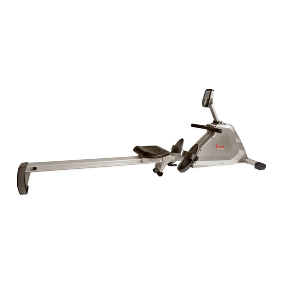
- Page 1 PROGRAMMABLE MAGNETIC ROWER SF-RW5854 USER MANUAL IMPORTANT! Please retain owner’s manual for maintenance and adjustment instructions. Your satisfaction is very important to us, PLEASE DO NOT RETURN UNTIL YOU HAVE CONTACTED US: support@sunnyhealthfitness.com or 1- 877 - 90SUNNY (877-907-8669).
-
Page 2: Important Safety Information
IMPORTANT SAFETY INFORMATION We thank you for choosing our product. To ensure your safety and health, please use this equipment correctly. It is important to read this entire manual before assembling and using the equipment. Safe and effective use can only be achieved if the equipment is assembled, maintained, and used properly. -
Page 3: Exploded Diagram
EXPLODED DIAGRAM 40 39 41 40... -
Page 4: Hardware Package
71 70 HARDWARE PACKAGE... -
Page 5: Parts List
PARTS LIST Description Spec. Description Spec. Computer Bolt M8*32 Nylon Nut M8*H7.5*S13 Nylon Nut d8*Φ20*2 Washer Adjusting Bolt M6*40 Bolt M8*90*20*S13 Adjusting U Seat Handlebar Nylon Nut Φ12.5*Φ8.2*10 Mesh Belt Spacer Φ32*17 End Cap Roller for Seat Slider Foam Grip Bolt M8*28 Front Stabilizer... - Page 6 Description Spec. Description Spec. Power Cord Volute Spring Outer PC Board for Sensor Seat Mesh Belt Wheel Bolt M10*112 Bearing 6300-2RS Φ19*2 Spacer C Clip Bearing 6000-ZZ Mesh Belt Plate Φ15*Φ10.2 Spacer Bearing Φ45*35 Mesh Belt Pulley Bearing 16003-2RS Outer Cover for Nylon Nut Mesh Belt Wheel 75L/R...
-
Page 7: Assembly Instructions
ASSEMBLY INSTRUCTIONS STEP 1: #25 M8*50*S14 2PCS #15 d8 2PCS Attach Front Stabilizer (No. 9) to Main d8*Φ 22*2 2PCS Frame (No. 14) using 2 Bolts (No. 25), 2 #A S13-14-15 1PC Spring Washers (No. 15), and 2 Washers (No. 12). Tighten and secure with Allen Wrench (No. - Page 8 STEP 3: Φ 10.9*80*14 1PC d6*Φ 16*1.2 1PC M6*16*S5 1PC Attach Seat (No. 31) onto Aluminum Φ 11.4*Φ 27*26 2PCS Rail (No. 44). M5*16*Φ 8.5 1PC M5*16*Φ 10 1PC Note: There is an arrow sticker marked on Seat (No. 31), please attach it as the #B S6 1PC #C S5 1PC arrow directs to prevent assembly in the...
- Page 9 STEP 5: #4 M8*90*20*S13 Connect Trunk Wire (No. 56) with #3 d8*Φ 20*2 2PCS Computer Wire (No. 1a). #2 M8*H7.5*S13 Connect Trunk Wire 2 (No. 28) with Computer Wire (No. 1b). #A S13-14-15 1PC Connect Trunk Wire 4 (No. 27) with #D S13-14 1PC Computer Wire (No.
-
Page 10: Exercise Computer
EXERCISE COMPUTER OPERATING INSTRUCTION: 1. Connect all of the cables to the monitor. 2. After turning on, all LCD segments will light up for 2 seconds and the Computer will start at level 1. The monitor will go to initial mode. NOTE: If the connection cables were installed incorrectly, motor will not run. - Page 11 FUNCTIONS: TIME: Exercise time will be shown on the display when exercising. If the computer is inactive for 256 seconds, it will enter sleep mode. To turn on the computer, press any button or signal input or start work out, all values will reset zero. Count up: Without setting the time value, the monitor will count up the time from 0:00 to 99:59.
- Page 12 PROGRAM: Preset Program: Program 1- Program 7 1. Press the +/- button to the desired program. 2. Press MODE to enter the program. 3. The Time display will flash, and then press the +/- button to set up the desired time to do the exercise.
- Page 13 PROGRAM 9 (PULSE PROGRAM) Computer will adjust the resistance level according to the pulse value, eg: if the current value is lower than desired value, the resistance will increase, otherwise, the resistance will decrease. 1. Press the +/- button to P9. 2.
-
Page 14: Adjustment Guide
ADJUSTMENT GUIDE PEDAL ADJUSTMENT The pedal strap is adjustable and can be personalized to fit the user’s foot size. MOVING THE MACHINE To move the machine, lift up Aluminum Rail (No. 44) until the transportation wheels on End Caps (No. 10L/R) touch the ground. - Page 15 ADJUSTMENT GUIDE When not in use, you can save space by folding the Aluminum Rail (No. 44). 1. Unscrew the L Knob (No. 16) until the taper completely with draws from the Aluminum Rail Link (No. 22), and at the same Figure A time, draw the L Knob (No.


Need help?
Do you have a question about the SF-RW5854 and is the answer not in the manual?
Questions and answers