Table of Contents
Advertisement
4025554/9
Installation and Maintenance Instructions
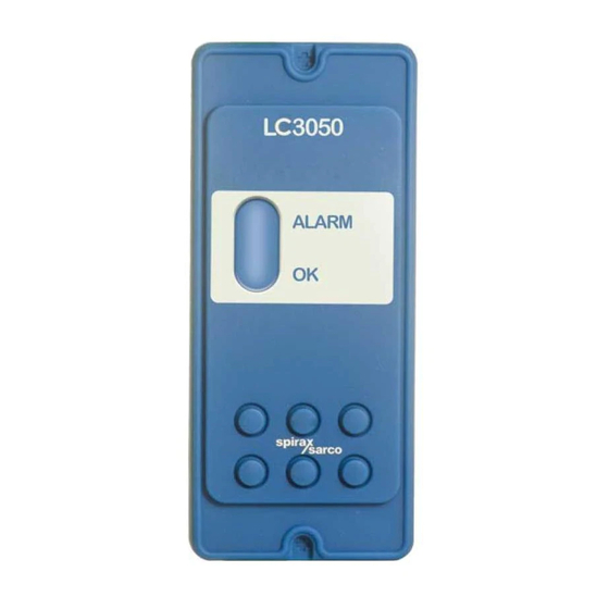
LC3050
ALARM
OK
IM-P402-131 EMM Issue 9
LC3050
Level Controller
AL
IM-P402-131
1. Safety information
2. User instructions and
delivery information
3. System overview
4. Mechanical installation
5. Electrical installation
6. Commissioning
7. Communications
8. Maintenance
9. Fault finding
10. Technical information
11. Appendix
- Data registers
© Copyright 2017
EMM Issue 9
1
Printed in GB
Advertisement
Table of Contents

Related Manuals for Spirax Sarco LC3050


Summary of Contents for Spirax Sarco LC3050
- Page 1 IM-P402-131 4025554/9 EMM Issue 9 LC3050 Level Controller Installation and Maintenance Instructions 1. Safety information 2. User instructions and delivery information LC3050 3. System overview 4. Mechanical installation ALARM 5. Electrical installation 6. Commissioning 7. Communications 8. Maintenance 9. Fault finding 10.
- Page 2 IM-P402-131 EMM Issue 9...
-
Page 3: Safety Information
This product meets all the Requirements of the Directive and is suitable for Class A Environments (i.e. Industrial). The LC3050 meets the requirements of the Directive by meeting the Controlling standard: EN 61326-1: 2006 - Electrical equipment for measurement control and laboratory use - EMC requirements Part 1: General requirements. - Page 4 The product may be exposed to interference above the limits of Heavy Industrial Immunity if: The product or its wiring is located near a radio transmitter. Excessive electrical noise occurs on the mains supply. Power line protectors (ac) should be installed if mains supply noise is likely. Protectors can combine filtering, suppression, surge and spike arrestors.
- Page 5 Failed product In the unlikely event of a fault condition to trigger the alarm with the LC3050 / LP30 low level system the standard Maintenance and Fault finding procedures listed in this instruction manual must be followed - Please refer to Section 9.
- Page 6 The product has gained its SIL2 rating on the assumption that electrolytic capacitors are to be replaced every 8 years. It is the responsibility of the user to maintain and operate the LC3050 / LP30 low level alarm system per the manufacturer’s instructions. Furthermore, regular inspection should indicate that all components are free of damage.
- Page 7 Cheltenham, Gloucestershire GL53 8ER, PRfsS Ltd have performed an assessment of the LC3050/LP30 with reference to the CASS methodologies and found it to meet the requirements of IEC61508-2:2010 Performing the safety functions stated in the associated report in both demand and continuous mode to a Safety Integrity Level of SIL2 when used in a 1oo1 architecture and SIL3 when used in a 1oo2 architecture.
- Page 8 The LC3050 is a single channel level alarm capable of measuring conductivity at a fixed point determined by the position of a Spirax Sarco Ltd LP30 High integrity low level alarm probe and is intended for low water level detection in steam and hot water boilers.
- Page 9 A Failure Mode Effects and Diagnostics Analysis (FMEDA) has been carried out as part of this assessment and has established the failure modes and random failure rates for the LC3050. According to BS EN 61508-2:2010 route 1 was used to determine the maximum safety integrity that may be claimed.
- Page 10 IEC61508-2, paragraph 7.4.3.1.2. The highest systematic SIL capability is SIL3 Fault Tolerance is ‘0’ for a single LC3050 as it has no inbuilt redundancy. (Note that the LC3050 is intended to be used in redundant pairs). Environment / stress criteria – FMEDA carried out using a quality factor and environmental factor of 1.
- Page 11 The achievement of functional safety relies not only on the satisfactory operation of the LC3050/LP30 system in response to a deviation in conductivity as measured by the sensor probe but also on the ability of a trained operator to take action in the event of a hazard or from failures revealed by calibration, proof testing or system failure;...
- Page 12 Symbols used within these Installation and Maintenance Instructions or on the product rating label Equipment protected throughout by double insulation or reinforced insulation. Functional earth (ground) terminal, to enable the product to function correctly. Not used to provide electrical safety. Clean earth / ground.
- Page 13 Determine the correct installation situation and direction of fluid flow. iv) Spirax Sarco products are not intended to withstand external stresses that may be induced by any system to which they are fitted. It is the responsibility of the installer to consider these stresses and take adequate precautions to minimise them.
- Page 14 1.9 Tools and consumables Before starting work ensure that you have suitable tools and / or consumables available. Use only genuine Spirax Sarco replacement parts. 1.10 Protective clothing Consider whether you and / or others in the vicinity require any protective clothing to protect against the hazards of, for example, chemicals, dust, high / low temperature, radiation, noise, falling objects, and dangers to eyes and face.
-
Page 15: Returning Products
1.16 Returning products Customers and stockists are reminded that under EC Health, Safety and Environment Law, when returning products to Spirax Sarco they must provide information on any hazards and the precautions to be taken due to contamination residues or mechanical damage which may present a health, safety or environmental risk. -
Page 16: All Rights Reserved
Spirax-Sarco Limited. 2.1 General description WARNING; In most countries, The Spirax Sarco LC3050 is a high / low steam boilers operating with level limiting monitor and alarm suitable for limited supervision require two use in conductive liquids. - Page 17 A full, manual test of the probe, cable, controller and associated circuits can be carried out using a front panel test button marked ALM. See Section 6 Commissioning. If two LC3050 controllers are present in the system, this manual test should be carried out on both.
-
Page 18: System Overview
The LC3050 unit is assembled from two PCB’s: the LC3 – 4025518 and the MB3 – 4025519. The LC3 – 4025518 contains all the safety electronics and there is no embedded software on this PCB. -
Page 19: Mechanical Installation
Note: Read the 'Safety information' in Section 1 before installing the product. At all times during installation, normal use or maintenance, the rear of the LC3050 in particular must be protected from environmental pollutants entering into the product. Therefore the product must be installed in a suitable industrial control panel or fireproof enclosure to provide impact and environmental protection. - Page 20 4.3 Installation on a chassis plate: Drill holes in chassis plate as shown in Figure 2. Fit unit to chassis plate and secure with 2 screws, nuts and washers, using the slots provided at the top and bottom of the case. Warning: Do not drill the product case or use self-tapping screws.
- Page 21 Fig. 2 Ø 4.2 mm Ø 4.2 mm Chassis plate / panel - 10 mm cutout diagram 45 mm 112 mm 92 mm 22.5 10 mm Ø 4.2 mm Ø 4.2 mm 67 mm 120 mm 8 mm 112 mm 120 mm IM-P402-131 EMM Issue 9...
-
Page 22: Electrical Installation
Use only the connectors supplied with the product, or spares obtained from Spirax Sarco Limited. Use of different connectors may compromise product safety and approvals. Ensure there is no condensation within the unit before installing and connecting the power. - Page 23 It is important that the cable screens (Figures 6 and 7) are connected as shown in order to comply with the electromagnetic compatibility requirements. All external circuits must meet and maintain the requirements of double / reinforced installation as stated in IEC 60364 or equivalent. Additional protection must be provided to prevent accessible parts (e.g.
- Page 24 5.2 Mains wiring notes: 1. Read Section 5.1, General Wiring notes, before attempting to wire the supply to the product. 2. Fuses must be fitted in all live conductors. Disconnect device conforming to Disconnect device conforming to IEC 60947-1 and IEC 60947-3 IEC 60947-1 and IEC 60947-3 100 mA ( T ) No.
- Page 25 4. The wiring diagrams show relays and switches in the Power off position. 110 / 120 Vac 100 mA(T) fuse Alarm lamp or bell Burner circuit 220 / 240 Vac Live supply from broken at alarm burner circuit 100 mA(T) Fit link 3A fuse fuse...
-
Page 26: Probe Wiring
5.3 Probe wiring The maximum cable length for both LP30 and LP31 probes is 50 m (164 ft). LP30 and LP31 UL probes only The LP30 and LP31 UL probes are supplied with four 18 AWG, 12" long colour coded flying leads. - Page 27 Signal circuit for high water level limiter (view from the top) Connect to Do not connect local earth in terminal 53 to the panel any other earth Optional external test button (normally open) Screen LP31 connector This terminal is internally connected Internal link to the probe body and Internal resistor...
-
Page 28: General Information
6. Commissioning 6.1 General information In normal boiler operation with the water level normal, the LC3050 green LED will be lit and the status indicators on the boiler control panel will indicate a normal water level. The green LED briefly extinguishes every few seconds showing that the automatic cyclic test is being carried out. -
Page 29: Infrared (Ir)
USER products are fitted with a graphics display and OEM products either have LED’s, or three digit displays. LC3050 unit is always an IR slave – no set-up or adjustment is needed. For further information on Infrared and RS485 communication, see User Installation and Maintenance Instructions. -
Page 30: System Maintenance
If, as a result of the cyclic self-test or a full manual test, the system detects a probe tip short to earth then the Probe Clearance Test Procedure (Section 5) in the LP30 IMI should be followed. All specialised testing accessories are supplied with the LC3050. LP30 Clean and inspect the LP30 annually, particularly the threaded contact surfaces between the tip and extension and the probe central electrode. -
Page 31: Fault Finding
9. Fault finding WARNING: Before fault finding read the Safety information in Section 1 and the General wiring notes in Section 5.1. Please note that there are hazardous voltages present and only suitably qualified personnel should carry out fault finding. The product must be isolated from the mains supply before touching any of the wiring terminals. - Page 32 Symptom Action 1. Probe cable to 'low alarm tip' connection is open circuit. 2. Comparator tip shorted to earth. Red LED 3. Earth open circuit. stays on 4. Probe wires crossed. (LP30 low 5. Low alarm tip shorted to comparator tip. alarm) 1.
- Page 33 Symptom Action Green LED flashes quickly on start-up, then red 1. No fault present – Controller self-checking circuitry has simulated LED lights a fault at the moment it was switched on, but is working normally. for about 12 seconds. Green LED then flashes approximately every...
-
Page 34: Technical Information
10.2 Returning faulty equipment Please return all items to your local Spirax Sarco representative, if this is not known, please contact Spirax Sarco via the website. Please ensure all items are suitably packed for transit (preferably in the original cartons). - Page 35 10.4 Environmental General Indoor use only 2 000 m (6 562 ft) Maximum altitude above sea level Ambient temperature limits 0 - 55 °C (32 - 131 °F) 80% up to 31 °C (88 °F) decreasing linearly to 50% at Maximum relative humidity 40 °C (104 °F) Overvoltage category...
- Page 36 Cable size 0.2 mm² (24 AWG) to 2.5 mm² (14 AWG). Stripping length 5 - 6 mm Caution:- Use only the connectors supplied by Spirax Sarco Ltd. Safety and Approvals may be compromised otherwise. Level probe cable/wires Type High temperature...
- Page 37 10.7 Output technical data Relay(s) Contacts 2 x single pole changeover relays (SPCO) Voltage ratings (maximum) 250 Vac Resistive load 3 amp @ 250 Vac Inductive load 1 amp @ 250 Vac ¼ HP (2.9 amp) @ 250 Vac ac motor load HP (3 amp) @ 120 Vac Pilot duty load C300 (2.5 amp) - control circuit/coils...
- Page 38 11. Appendix - Data registers Parameters and register data Register Parameters 7 - Identity Note: When the device is an IR slave and there is a temporary error in the IR Master-Slave comms, an offset of +32768 is added to the identification value of that particular slave stored in the master's database.
- Page 39 IM-P402-131 EMM Issue 9...
- Page 40 IM-P402-131 EMM Issue 9...
Need help?
Do you have a question about the LC3050 and is the answer not in the manual?
Questions and answers