
Related Manuals for Vista VK2-HD30IR-PM


Summary of Contents for Vista VK2-HD30IR-PM
- Page 1 Quick Installation Guide VK2-HD30IR-PM Please read this guide thoroughly before use and keep it handy for future reference.
- Page 2 Norbain SD, 210 Wharfedale Road, Winnersh Triangle, Wokingham, Berkshire RG41 5TP, England. UK +44 (0) 118 912 5000 / Vista Technical Support +44 (0) 118 912 5125 Note: You should be at the equipment and ready with details before calling Technical Support.
-
Page 3: Important Safety Instructions
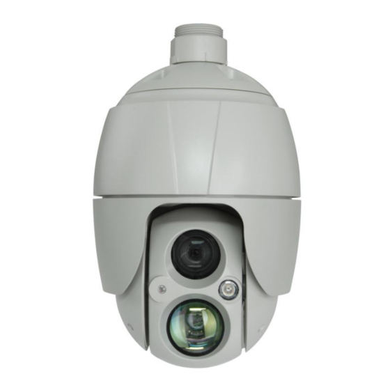
CAUTION RISK OF ELECTRIC SHOCK DO NOT OPEN CAUTION: TO REDUCE THE RISK OF ELECTRIC SHOCK, DO NOT REMOVE COVER (OR BACK) NO USER-SERVICEABLE PARTS INSIDE. REFER SERVICING TO QUALIFIED SERVICE PERSONNEL. IMPORTANT SAFETY INSTRUCTIONS Read these instructions. Keep these instructions. Heed all warnings. - Page 4 DISPOSE OF USED BATTERIES ACCORDING TO THE INSTRUCTIONS. 1 Introduction The VK2-HD30IR-PM, is a 1080p camera with 30:1 lens in a pendant mount IP66 / IK10 housing. Combined with a fixed IR for wide angle and tracking IR for upto 300m illumination, this is designed for long range internal and external use.
-
Page 5: Key Features
1.2 Key Features • HD video The network camera offers the highly efficient H.264 video compression, which drastically reduces bandwidth and storage requirements without compromising image quality. Motion JPEG is also supported for increased flexibility. • Dual or Triple Streams The network camera can deliver dual or triple video streams simultaneously at full frame rate in all resolutions up to Full-HD (1920 x 1080p) using Motion H.264 and JPEG. -
Page 6: Installation
2 Installation 2.1 Mounting the Camera Please see the Vista Solution guide for available bracketery and mounting options. The wall or ceiling mount must be attached to a structural object such as hard wood, concrete that will support the weight of the mount and dome camera. -
Page 7: Basic Configuration Of Camera System
2.2 Basic Configuration of Camera System Connector Wire Color Description Power jack BLACK CAMERA POWER Ethernet, RJ-45 port compatible with RJ-45 BLACK 10/100Mbps RCA jack BLACK AUDIO INPUT RCA jack GRAY AUDIO OUTPUT YELLOW ALARM INPUT 1 WHITE ALARM INPUT 2 5-pin cable VIOLET ALARM INPUT 3... -
Page 8: Micro-Sd Card Insertion
2.3 Micro-SD Card Insertion User can install and change Micro-SD card as shown in the following picture. 1. Open the Micro-SD card cover. 2. Install or change Micro-SD card. 3. Tightly close the Micro-SD card cover to ensure waterproofness - THIS IS A PRIMARY SEAL. 2.4 Connections •... - Page 9 – Be careful not to reverse the polarity when you connect the power cable. – If you use PoE to supply power to the camera, you must use the included mains powered PoE (Power over Ethernet) injector included with the camera.
-
Page 10: Network Connection & Ip Assignment
2.4.1 Network Connection & IP Assignment The camera supports the operation through the network. When a camera is first connected to the network, it is necessary to allocate an IP address to the device with the SmartManager utility on the CD. (Default IP 192.168.30.220) 1) Connect the network camera/device to the network and power up. -
Page 11: Operation
3 Operation The network camera can be used with Windows operating system and browsers. The recommended browsers are Internet Explorer, Safari, Firefox, Opera and Google Chrome with Windows. NOTE: To view streaming video in Microsoft Internet Explorer, set your browser to allow ActiveX controls. -
Page 12: Access From The Internet
3.2 Access from the internet Once connected, the network camera is accessible on your local network (LAN). To access the network camera from the Internet you must configure your broadband router to allow incoming data traffic to the network camera. To do this, enable the NAT traversal feature, which will attempt to automatically configure the router to allow access to the network camera. -
Page 13: Live View Page
3.4 Live View Page The Live View page comes in several screen modes: 1920x1080, 1280x1024, 1280x720(960), 1024x768, 704x480(576), 640x480(360) and 320x240. Users are allowed to select the most suitable one out of those modes. Adjust the mode in accordance with your PC specifications and monitoring purposes. - Page 14 2) Control toolbar The live viewer toolbar is available in the web browser page only. It displays the following buttons: The Stop button stops the video stream being played. Pressing the key again toggles the play and stop. The Play button connects to the network camera or starts playing a video stream. The Pause button pauses the video stream being played.
- Page 15 3.5 Playback The Playback window contains a list of recordings made to the memory card. It shows each recording’s start time, length, the event type used to start the recording, calendar and time slice bar indicates if the recording is existed or not. The description of playback window follows.
- Page 16 3) Time Chart Display an hour-based search screen for the chosen date. If there is recording data, a blue section will be displayed on a 24-hour basis. If you select a particular hour in the chart, a yellow square on the hour will be displayed. 4) Speaker Control Bar Use this scale to control the volume of the speakers.
-
Page 17: Network Camera Setup
3.6 Network Camera Setup This section describes how to configure the network camera. Administrator has unrestricted access to all the Setup tools, whereas Operators have access to the settings of Basic Configuration, which are Live View, Video & Image, Audio, Event, Dome Configuration, and System. -
Page 18: System Requirement For Web Browser
• Using the Reset button: Follow the instructions below to reset the network camera to the factory default settings using the Reset button. 1. Switch off the network camera by disconnecting the power adapter. 2. Open the Micro-SD card cover. 3. - Page 19 Vista 210 Wharfedale Road Winnersh Triangle Wokingham Berkshire. RG41 5TP (Subject to change without notice) Version 1.0 50304036A...
Need help?
Do you have a question about the VK2-HD30IR-PM and is the answer not in the manual?
Questions and answers