
Related Manuals for BLAUBERG SMART


Summary of Contents for BLAUBERG SMART
- Page 1 Smart Smart Smart IR Smart IR model (check applicable) is recognized as serviceable Service instruction SALES DATE MANUFACTURED ON (DATE): SOLD APPROVAL MARK SMART-EN-04...
-
Page 2: Complete Set
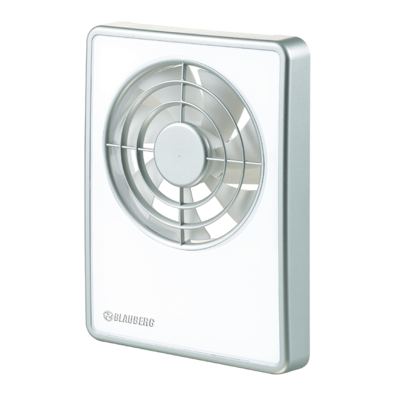
BLAUBERG Smart fan is the combination of design, high performance and silence operation multiplied by intelligence. While you enjoy your rest, the BLAUBERG Smart guards your comfort. It is enough to connect it to power mains to have the ideal microclimate in your bathroom automatically maintained. - Page 3 Table 2 Functions Type SMART SMART IR Table 3 The fan has four basic modes and one extra mode: SLEEP - in this mode the fan does not move and it is ready to accept a signal from the sensors or from the external switch.
-
Page 4: Operation Rules
Dimensions [mm] Model SMART/ SMART IR 155,5 100/125 Table 4 OPERATION RULES The fan is rated for connection to single-phase ac 100-240 V / 50-60 Hz power supply and is designed for continuous operation always connected to power mains. The fan is rated for operation at ambient temperature from +1 °C up to +45 °C. -
Page 5: Mounting And Setup
The single-phase power grid must comply with the acting local electrical norms and standards. The fixed electrical wiring must be equipped with an automatic circuit breaker that is used for connection of the fan to power mains with gap on all poles at least 3 mm. Make sure the impeller and the casing are not damaged before starting installation. - Page 7 The fan is equipped with a removable grille. To release the grille from the face cover press the latches gently. During mounting of the grille on the face cover back match the latches and corresponding slots in the cover and insert to click. The arrow on the grille back side must be directed to the shorter side close to the hole.
-
Page 8: Fan Mounting
FAN MOUNTING... - Page 10 Follow one of four available wiring diagrams to connect the fan to power mains. The model SMART IR is fitted with extra terminal LI that is used for connection of the light lamp up to 200 W/230 W or 100 W/130 V.
- Page 11 24 HOURS mode is not available. After receipt of a signal from the motion sensor (for SMART IR model only) the fan turns to QUIET mode. Some time after no movement is detected any more the fan reverts to the previous mode.
- Page 12 OPERATING PATTERN - DIAGRAM 1...
- Page 13 OPERATING PATTERN - DIAGRAM 2...
- Page 14 OPERATING PATTERN - DIAGRAM 3...
- Page 15 OPERATING PATTERN - DIAGRAM 4...
- Page 16 MAXIMAL mode air capacity (Ø125 / Ø100), m /h MAXIMAL humidity extraction mode turn-on delay timer settings, min turn-off delay timer settings, min humidity timer settings, min Motion sensor (for model SMART IR only) 24 HOURS mode Table 5 CONTROL PANEL SMART SMART IR...
-
Page 17: Remote Controller
ATTENTION! The maximum sensitive range of the remote controller is 3m. For easy control please direct the remote controller straight to the fan. The temperature adjustment buttons " " on the remote controller are not activated (applicable for the SMART THERMO model). Button Operation description Turning the fan on/off... - Page 18 FAN MODE INDICATION motion sensor / SLEEP mode external switch is activated 2 Sek. Green Green 24 HOURS mode Humidity extraction mode 2 Sek. Turn-on delay timer Interval ventilation mode 0.5 Sek. 1 Sek. Green QUIET MODE SPEED ADJUSTMENT By default this speed provides air capacity 83/72 m3/h (Ø125 / Ø100).
- Page 19 SELECTION OF HUMIDITY EXTRACTION MODE If humidity changes the fan is turned on to higher speed to remove excessive humidity. After humidity stabilization in the room the humidity timer is activated and the fan runs within time period set by the humidity extraction timer and then reverts to the previous mode.
- Page 20 0 min 2 min 5 min ACTIVATION OF MOTION SENSOR (SMART IR) To turn the motion sensor on, press the "On/Off move" button on the control panel or the " “ button on the remote controller. The indicator light "STATUS" under this button confirms that the motion sensor is turned on.
-
Page 21: Reset To Factory Settings
ACTIVATION OF MODE 24 HOURS In this mode the fan runs with minimum air capacity before the humidity sensor, motion sensor or external switch is activated. Press the "24 HOURS" button on the control panel or the " “ button on the remote controller to activate this function. The green indicator light under this button on the control panel confirms that this mode is activated. -
Page 22: Maintenance
MAINTENANCE Any servicing and maintenance operations of the fan are allowed after it is disconnected from power mains only. Maintenance means regular cleaning of the fan surfaces from dirt and dust. To clean the fan, wipe its surfaces with a cloth wetted in a mild soap solution, then wipe the surfaces dry. -
Page 23: Storage And Transportation Rules
STORAGE AND TRANSPORTATION RULES Transport the product in the manufacturer's original package. Transportation is allowed by any transportation vehicle provided that the product is protected against weather influence. Store the delivered product in the manufacturer's original packing box in a dry ventilated premise with the ambient temperature from +5°C up to + 40°C and relative humidity less than 80%.
Need help?
Do you have a question about the SMART and is the answer not in the manual?
Questions and answers