Table of Contents
Advertisement
Quick Links
Advertisement
Table of Contents

Related Manuals for BLAUBERG TRIO-100


Summary of Contents for BLAUBERG TRIO-100
- Page 1 AXIAL FAN TRIO User’s manual...
-
Page 2: Table Of Contents
CONTENTS Delivery set ................................................6 Brief description ..............................................6 Operation guidelines ............................................6 Designation key ..............................................7 Installation................................................7 Electronics operation algorithm ....................................... 8 Technical maintenance ........................................... 10 Troubleshooting ..............................................10 Storage and transportation regulations ....................................11 Manufacturer’s warranty ..........................................12 This user’s manual is a main operating document intended for technical, maintenance, and operating staff. - Page 3 READ THE USER’S MANUAL CAREFULLY BEFORE PROCEEDING WITH INSTALLATION WORKS. COMPLIANCE WITH THE MANUAL REQUIREMENTS ENSURES RELIABLE OPERATION AND LONG SERVICE LIFE OF THE UNIT. KEEP THE USER’S MANUAL AVAILABLE AS LONG AS YOU USE THE UNIT. YOU MAY NEED TO RE- READ THE INFORMATION ON THE PRODUCT SERVICING.
- Page 4 the impeller and the casing before starting installation. The casing internals must be free of any foreign objects that can damage the impeller blades. • While mounting the unit, avoid compression of the casing! Deformation of the casing may result in the motor jam and noisy operation.
- Page 5 • Do not sit on the unit and do not put objects on it. • The unit is allowed to be used by children aged from 8 years old and above and persons with reduced physical, sensory, or mental capabilities or no experience and knowledge provided that they have been given supervision or instruction regarding safe use of the unit and understand the risks involved.
-
Page 6: Delivery Set
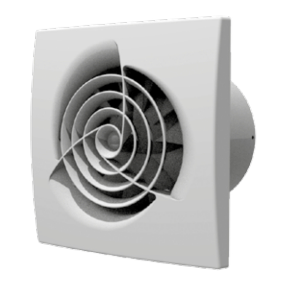
DELIVERY SET — 1 pc. Screws and dowels — 4 pcs. Plastic screwdriver (only for the models with a timer) — 1 pc. User’s manual — 1 pc. Packing box — 1 pc. BRIEF DESCRIPTION The unit described herein is an axial fan for exhaust ventilation of small to medium-sized premises heated during winter. The fan design can also include a backdraft damper to prevent back flow when the fan is switched off. -
Page 7: Designation Key
DESIGNATION KEY Trio Х 100 Х Х Unit voltage: _: supply voltage 220-240 V, power frequency 50 Hz 220-240 V/60 Hz: supply voltage 220-240 V, power frequency 60 Hz 12: low voltage motor 12 V/50 Hz Additional options: S: pull cord switch T: turn-off delay timer TR: turn-on and turn-off delay timer ST: pull cord switch and turn-off delay timer... -
Page 8: Electronics Operation Algorithm
ELECTRONICS OPERATION ALGORITHM The fan with the T timer activates upon control voltage application to the S input terminal by the S1 external switch (e.g. indoor light switch). After the control voltage is off, the fan continues to operate within the time set by the timer ranging from 2 to 30 minutes. - Page 9 — To adjust the fan turn-on delay time, turn the control knob T clockwise to increase and counter-clockwise to decrease the turn-on delay time respectively, adjustable from 0 up to 2 minutes. — To adjust the fan turn-off delay time, turn the control knob T clockwise to increase and counter-clockwise to decrease the turn-off delay time respectively, adjustable from 2 up to 30 minutes.
-
Page 10: Technical Maintenance
TECHNICAL MAINTENANCE The fan maintenance periodicity is at least once per 6 months. Maintenance steps: • Disconnect the fan from power supply and make sure electricity has been turned off (Fig. 18). • Remove the front and the decorative panels, wipe the fan with a dry cloth or a brush (Fig. 19). •... -
Page 11: Storage And Transportation Regulations
STORAGE AND TRANSPORTATION REGULATIONS • Store the unit in the manufacturer’s original packaging box in a dry closed ventilated premise with temperature range from +5 ˚С to +40 ˚С and relative humidity up to 70 %. • Storage environment must not contain aggressive vapors and chemical mixtures provoking corrosion, insulation, and sealing deformation. -
Page 12: Manufacturer's Warranty
MANUFACTURER’S WARRANTY The product is in compliance with EU norms and standards on low voltage guidelines and electromagnetic compatibility. We hereby declare that the product complies with the provisions of Electromagnetic Compatibility (EMC) Directive 2014/30/ EU of the European Parliament and of the Council, Low Voltage Directive (LVD) 2014/35/EU of the European Parliament and of the Council and CE-marking Council Directive 93/68/EEC. - Page 13 components caused by the user. • Redesign or engineering changes to the unit. • Replacement and use of any assemblies, parts and components not approved by the manufacturer. • Unit misuse. • Violation of the unit installation regulations by the user. •...
- Page 14 D, mm B, mm L, mm Trio 100 Trio 150 ø D...
- Page 16 ... 100/150 ... 100/150 ... 100/150 S Fan does not run Contact of S1 switch or pull cord switch is CLOSED Fan runs Contact of S1 switch or pull cord switch is OPENED Activation of turn-off delay timer (2-30 minutes)
- Page 17 ... 100/150 TR Fan does not run Contact of S1 switch or pull cord switch is CLOSED Switch is deactivated during countdown of turn-on delay timer Fan runs Contact of S1 switch or pull cord switch is OPENED Activation of turn-off delay timer (2-30 minutes)
- Page 18 ... 100/150 ... 100/150 S Fan does not run Contact of S1 switch or pull cord switch is CLOSED Humidity exceeds set point Fan runs Contact of S1 switch or pull cord switch is OPENED Fan runs Humidity is below set point Activation of turn-off...
- Page 19 ... V2 100/150 R Fan runs at speed 1 Switch contact S1 is CLOSED Activation of turn-on delay timer (0-2 minutes) Switch contact S1 is OPENED during the turn-on delay timer operation Fan runs at speed 2 S1 switch contact is OPENED Activation of turn-off...
- Page 20 ... V2 100/150 Fan runs at speed 1 Switch contact S1 is CLOSED Humidity exceeds set point Activation of turn-on delay timer (45 seconds) Switch contact S1 is OPENED Fan runs at speed 2 during the turn-on delay timer operation Humidity is below set point Activation of turn-off...
- Page 21 ... V2 100/150 S1 switch is in L position Fan runs at speed 2 Fan runs at speed 1...
- Page 23 Quality Inspector’s Stamp Sold by (name and stamp of the seller) Manufacture Date Purchase Date...
- Page 24 Т ТR Trio SТ 220 V/60 Hz Н SН www.blaubergventilatoren.de B216EN-01...
Need help?
Do you have a question about the TRIO-100 and is the answer not in the manual?
Questions and answers