Table of Contents
Advertisement
Quick Links
Advertisement
Table of Contents

Related Manuals for BLAUBERG Trio


Summary of Contents for BLAUBERG Trio
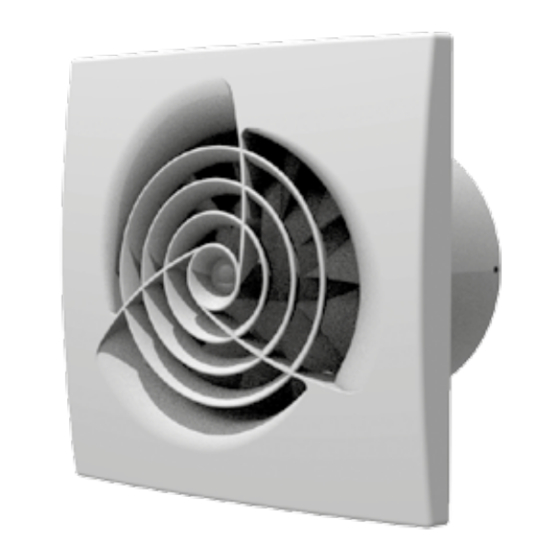
- Page 1 AXIAL FAN Trio User’s manual...
-
Page 2: Table Of Contents
Manufacturer’s warranty ..........................................15 This user’s manual is a main operating document intended for technical, maintenance, and operating staff. The manual contains information about purpose, technical details, operating principle, design, and installation of the Trio unit and all its modifications. - Page 3 PLEASE READ THE USER’S MANUAL CAREFULLY PRIOR TO INSTALLING, CONNECTION TO POWER MAINS AND OPERATING THE UNIT. THE MANUFACTURING COMPANY SHALL NOT BE RESPONSIBLE FOR DAMAGE TO HEALTH AND PROPERTY OF THE CUSTOMER CAUSED BY THE CUSTOMER’S VIOLATING THE USER’S MANUAL. FOLLOW THE USER’S MANUAL REQUIREMENTS TO ENSURE DURABLE OPERATION OF THE UNIT, ITS MECHANICAL AND ELECTRICAL RELIABILITY.
- Page 4 of any foreign objects that can damage the impeller blades. While mounting the unit, avoid compression of the casing! Deformation of the casing may result in motor jam and excessive noise. Misuse of the unit and any unauthorised modifications are not allowed.
- Page 5 characteristics, design, or configuration of its products at any time in order to incorporate the latest technological developments. Never touch the unit with wet or damp hands. Never touch the unit when barefoot. This appliance can be used by children aged from 8 years and above and persons with reduced physical, sensory or mental capabilities or lack of experience and knowledge if they have been given supervision or instruction concerning use of the appliance in a safe way and...
- Page 6 Connection to the mains must be made through a disconnecting device, which is integrated into the fixed wiring system in accordance with the wiring rules for design of electrical units, and has a contact separation in all poles that allows for full disconnection under overvoltage category III conditions.
-
Page 7: Delivery Set
DELIVERY SET — 1 pc. Screws and dowels — 4 pcs. Plastic screwdriver (only for the models with a timer) — 1 pc. User’s manual — 1 pc. Packing box — 1 pc. BRIEF DESCRIPTION The unit described herein is an axial fan for exhaust ventilation of small and medium-sized utility spaces. The fan is designed for connection to Ø... -
Page 8: Designation Key
DESIGNATION KEY Trio V2 100 S e 12 Unit voltage: _: 220-240 V/50 Hz 220 V/60 Hz: supply voltage 220 V, power frequency 60 Hz 12: low voltage motor 12 V/50 Hz Differences from the baseline model _: ball bearing and a backdraft damper with a membrane of light by default... -
Page 9: Installation
INSTALLATION The fan is designed for wall mounting (with motors on sliding and ball bearings) or ceiling mounting and can be used to discharge air directly outside through a round duct or through a duct system. In case of installation through a duct system, select the duct cross section in accordance with the fan size (Fig. 1). 1. - Page 10 The fan mounting sequence is shown in Fig. 4-12. The fan wiring diagrams are shown in Fig. 13-18. Terminal designations on wiring diagrams: L — line/~12 V S1 — external switch N — neutral/~12 V QF — double pole circuit breaker S —...
-
Page 11: Electronics Operation Algorithm
ELECTRONICS OPERATION ALGORITHM The fan with the timer (T) activates upon control voltage application to the S input terminal by the S1 external switch (e.g. indoor light switch). After the control voltage is off, the fan continues to operate within the time set by the timer ranging from 2 to 30 minutes. - Page 12 — To adjust the fan turn-on delay time, turn the control knob T clockwise to increase and counter-clockwise to decrease the turn-on delay time set point, adjustable from 0 up to 2 minutes. — To adjust the fan turn-off delay time, turn the control knob T clockwise to increase and counter-clockwise to decrease the turn-off delay time set point, adjustable from 2 up to 30 minutes.
-
Page 13: Technical Maintenance
TECHNICAL MAINTENANCE The fan maintenance periodicity is at least once per 6 months. Maintenance steps: • Disconnect the fan from power supply and make sure electricity has been turned off (Fig. 19). • Remove the front and the decorative panels, wipe the fan with a dry cloth or a brush (Fig. 20). •... -
Page 14: Storage And Transportation Regulations
STORAGE AND TRANSPORTATION REGULATIONS • Store the unit in the manufacturer’s original packaging box in a dry closed ventilated premise with temperature range from +5 ˚C to +40 ˚C and relative humidity up to 70 %. • Storage environment must not contain aggressive vapors and chemical mixtures provoking corrosion, insulation, and sealing deformation. -
Page 15: Manufacturer's Warranty
MANUFACTURER’S WARRANTY The product is in compliance with EU norms and standards on low voltage guidelines and electromagnetic compatibility. We hereby declare that the product complies with the provisions of Electromagnetic Compatibility (EMC) Directive 2014/30/ EU of the European Parliament and of the Council, Low Voltage Directive (LVD) 2014/35/EU of the European Parliament and of the Council and CE-marking Council Directive 93/68/EEC. - Page 16 components caused by the user. • Redesign or engineering changes to the unit. • Replacement and use of any assemblies, parts and components not approved by the manufacturer. • Unit misuse. • Violation of the unit installation regulations by the user. •...
- Page 17 D [mm] B [mm] L [mm] Trio100 Trio 150 ø D ...2...
- Page 19 ... 100/150 ... 100/150 ... 100/150 S Fan does not run 8 mm max. Contact of S1 switch or pull cord switch is CLOSED Fan runs Contact of S1 switch or pull cord switch is OPENED Activation of turn-off delay timer (2-30 minutes)
- Page 20 ... 100/150 TR Fan does not run Contact of S1 switch or pull cord switch is CLOSED Activation of turn-on delay timer (0-2 minutes) Switch is deactivated during countdown of turn-on delay timer Fan runs Contact of S1 switch or pull cord switch is OPENED Activation of turn-off...
- Page 21 ... 100/150 ... 100/150 S Fan does not run Contact of S1 switch or pull cord switch is CLOSED Humidity exceeds set point Fan runs Contact of S1 switch or pull cord switch is OPENED Fan runs Humidity is below set point Activation of turn-off...
- Page 22 ... V2 100/150 R Fan runs at speed 1 Switch contact S1 is CLOSED Activation of turn-on delay timer (0-2 minutes) Switch contact S1 is OPENED during the turn-on delay timer operation Fan runs at speed 2 S1 switch contact is OPENED Activation of turn-off...
- Page 23 ... V2 100/150 Fan runs at speed 1 Switch contact S1 is CLOSED Humidity exceeds set point Activation of turn-on delay timer (45 seconds) Switch contact S1 is OPENED Fan runs at speed 2 during the turn-on delay timer operation Humidity is below set point Activation of turn-off...
- Page 24 ... V2 100/150 S1 switch is in L position Fan runs at speed 2 Fan runs at speed 1...
- Page 27 Quality Inspector’s Stamp Sold by (name and stamp of the seller) Manufacture Date Purchase Date...
- Page 28 Trio 220 V/60 Hz www.blaubergventilatoren.de B216EN-03...
Need help?
Do you have a question about the Trio and is the answer not in the manual?
Questions and answers