TorcUP TU-2 Manual
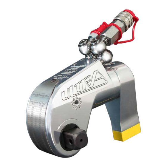
Tu series
square drive hydraulic torque wrenches
Hide thumbs
Also See for TU-2:
- Operation and maintenance manual (22 pages) ,
- Operation and maintenance manual (64 pages)
Advertisement
Quick Links
TU Series
OPERATION AND MAINTENANCE
MANUAL
TU Series
Square Drive Hydraulic Torque Wrenches
MODELS TU-2, TU-3, TU-5, TU-7, TU-11, TU-20, TU-27 & TU-60
1025 Conroy Place, Easton, PA. 18040 U.S.A.
Phone: +1 610-250-5800
Fax: +1 610-250-2700
Toll Free: 1-888-TORCUP-1
Email: sales@torcup.com
Website: www.torcup.com
Advertisement

Subscribe to Our Youtube Channel
Related Manuals for TorcUP TU-2


Summary of Contents for TorcUP TU-2
- Page 1 TU Series OPERATION AND MAINTENANCE MANUAL TU Series Square Drive Hydraulic Torque Wrenches MODELS TU-2, TU-3, TU-5, TU-7, TU-11, TU-20, TU-27 & TU-60 Phone: +1 610-250-5800 Fax: +1 610-250-2700 Toll Free: 1-888-TORCUP-1 Email: sales@torcup.com 1025 Conroy Place, Easton, PA. 18040 U.S.A.
-
Page 2: Using The Tool
Version 2: 2016 September NOTICE Series TU-2, TU-3,TU-5, TU-7, TU-11, TU-20, TU-27 and TU-60 Square Drive Hydraulic Torque Wrenches are designed for installing and removing threaded fasteners requiring precise high torque during bolt makeup and maximum torque during bolt breakout. -
Page 3: Failure To Observe The Following Warnings Could Result In Injury
Avoid sharp bends and kinks that will cause severe back-up pressure in hoses and lead to premature hose failure. • Use accessories recommended by TorcUP. • Use only impact sockets and accessories. Do not use hand (chrome) sockets or accessories. -
Page 4: Setting The Torque
To change the direction of rotation for models TU-2 TU-3, TU-7 and TU-11 simply push the square drive into the housing until the drive projects out the opposite side of the tool. For models TU-5, TU-20, TU-27 and TU-60, loosen and remove the square drive retaining knob and pull the square drive out of the housing. - Page 5 SETTING THE REACTION ARM The function of a reaction device is to hold the tool in position against the forces generated to tighten or loosen bolts or nuts. Hydraulic wrenches generate tremendous force. An improperly positioned reaction arm may result in operator injury or damage to tooling.
-
Page 6: Operating The Wrench
OPERATING THE WRENCH Square Drive Position for Loosening and Tightening (Dwg.02) The position of the square drive relative to the shroud determines whether the action will tighten or loosen the nut. (Refer to Dwg. 02 for application examples). The power stroke of the piston assembly will always turn the square drive toward the shroud. - Page 7 LUBRICATION MARINE MOLY GREASE Lubrication frequency is dependent on factors known only to the user. The amount of contaminants in the work area is one factor. Tools used in a clean room environment will obviously require less service than a tool used outdoors and dropped in loose dirt or sand. Marine Moly Grease is formulated not to wash out of the tool in areas where lubrication is critical.
- Page 8 TU Series Wrench Technical & Dimensional Data Model Number TU-2 TU-3 TU-5 TU-7 Square drive 3/4” 1” 1 1/2” 1 1/2” Min. Torque (ft/lbs) Max. Torque (ft/lbs) 1270 3330 5500 7400 Min. Torque (nm) 1003 Max. Torque (nm) 1722 4514...
- Page 9 TU Series Wrench Technical & Dimensional Data Model Number TU-11 TU-20 TU-27 TU-60 Square drive 1 1/2” 2 1/2” 2 1/2” 2 1/2” Min. Torque (ft/lbs) 1100 1940 2720 5800 Max. Torque (ft/lbs) 11010 20625 27200 58000 Min. Torque (nm) 1491 2630 3687...
- Page 12 2015 - March...
- Page 26 TU Series Wrench Available Accessories...
-
Page 27: Maintenance Section
MAINTENANCE SECTION Always turn off the power supply. Bleed off hydraulic fluid from the hose connections on the cylinder assembly and disconnect the hoses before WARNING attempting to repair or perform maintenance on this tool. Always wear eye protection when operating or performing maintenance on this tool. DISASSEMBLY GENERAL INSTRUCTIONS 1. - Page 28 Hold the shroud in position until the screws are removed and control the flex of the loose end. DISASSEMBLY OF THE TU-2, TU-3, TU-7, AND TU-11 CYLINDER ASSEMBLIES 1. Clamp the housing (1) in copper–covered or leather–covered vise jaws with the inlet end upward and using a 1/4”...
- Page 29 MAINTENANCE SECTION In the following step, the shroud will spring to a straightened position CAUTION when the screws at one end are removed. Hold the shroud in position until the screws are removed and control the flex of the loose end. DISASSEMBLY OF THE TU-5, TU-20, TU-27, AND TU-60 CYLINDER ASSEMBLIES Note: TU-20 part numbers are bold.
- Page 30 NOTICE damaged parts. ASSEMBLY OF THE TU-2, TU-3, TU-7, AND TU-11 CYLINDER ASSEMBLIES 1. Install the cylinder ring (35) into the groove at the inlet end of the housing. 2. Clamp the housing (1) in copper–covered or leather–covered vise jaws with the inlet end facing downward.
- Page 31 MAINTENANCE SECTION 18. Use a hex wrench to loosen the square drive locking pin (15) enough so that the square drive pin is flush with the square drive. 19. Insert the square drive into the housing through the drive sleeves (18) and tighten the drive locking pin so that the square drive can slide freely without sliding out.
- Page 32 MAINTENANCE SECTION 17. Install the square drive sleeves (18) (19) with the small hub end leading. The small hub must engage the recess in the drive plate assembly. Install the sleeve retaining rings (34) (33). 18. Insert the square drive (14) (17) into the housing through the drive sleeves (18) (19). Install the square drive retaining knob (17) (18) in the end of the square drive and tighten.
- Page 33 MAINTENANCE SECTION ASSEMBLY OF THE TU REACTION ARM (For all models except TU-20) 1. If the reaction arm cover was removed, push it onto the end of the reaction arm and secure it with the cover screws. 2. For TU-60 model only: Install the cover roll pin into the reaction arm and cover. 3.
- Page 34 MAINTENANCE SECTION ASSEMBLY OF THE TU-20 REACTION ARM 1. If the reaction arm cover was removed, push it onto the end of the reaction arm and insert the cover roll pin to retain the cover using a hammer. 2. Assemble the gate lever to the gate lever link using the gate link pin. 3.
-
Page 35: Troubleshooting Guide
TROUBLESHOOTING GUIDE Trouble Probable Cause Solution Couplers are not securely Check the coupler connections, and attached to the tool or pump make certain that they are connected. Coupler is defective Replace any defective coupler. Piston will not advance or Defective remote control Replace the switch and/or control retract switch... - Page 36 SAVE THESE INSTRUCTIONS DO NOT DESTROY NOTES: Phone: +1 610-250-5800 Fax:+1 610-250-2700 Toll Free: 1-888-TORCUP-1 Email: sales@torcup.com 1025 Conroy Place, Easton, PA. 18040 U.S.A. Website: www.torcup.com...
Need help?
Do you have a question about the TU-2 and is the answer not in the manual?
Questions and answers