Advertisement
Quick Links
TX Series
OPERATION AND MAINTENANCE
MANUAL
TX Series
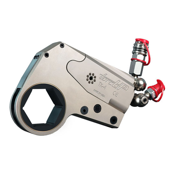
Low Profile Hydraulic Torque Wrenches
MODELS TX-1, TX-2, TX-4, TX-8, TX-16, TX-32, TX-45
1025 Conroy Place, Easton PA 18040 U.S.A.
Phone: +1 610-250-5800
Fax: +1 610-250-2700
Toll Free: 1-888-TORCUP-1
Email: sales@torcup.com
Website: www.torcup.com
1
Advertisement

Related Manuals for TorcUP TX Series


Summary of Contents for TorcUP TX Series
- Page 1 TX Series OPERATION AND MAINTENANCE MANUAL TX Series Low Profile Hydraulic Torque Wrenches MODELS TX-1, TX-2, TX-4, TX-8, TX-16, TX-32, TX-45 Phone: +1 610-250-5800 Fax: +1 610-250-2700 Toll Free: 1-888-TORCUP-1 Email: sales@torcup.com 1025 Conroy Place, Easton PA 18040 U.S.A. Website: www.torcup.com...
-
Page 2: Using The Tool
TorcUP Inc. is not responsible for customer modification of tools for applications on which TorcUP Inc. was not consulted. -
Page 3: Failure To Observe The Following Warnings Could Result In Injury
Avoid sharp bends and kinks that will cause severe back-up pressure in hoses and lead to premature hose • failure. Use accessories recommended by TorcUP. • Use only impact sockets and accessories. Do not use hand (chrome) sockets or accessories. -
Page 4: Connecting The Tool
PLACING THE TOOL IN SERVICE CONNECTING THE TOOL 1. Attach the twin line hose to the Dwg. 1 swivel inlets of the square drive torque wrench using the spring– loaded quick connect ends. 2. Connect the opposite ends of the hose to the pump in the same manner. - Page 5 PLACING THE TOOL IN SERVICE 3. After having turned the pump on and presetting the pressure for the correct torque, depress the remote control button to advance the piston assembly. If the notch in the piston rod did not engage the retract pin in the ratchet link when the link was joined to the housing, it will engage the pin automatically during the first advance stroke.
- Page 6 TX Series Wrench Technical & Dimensional Data Model Number TX-1 TX-2 TX-4 TX-8 Min. Torque (ft/lbs) Max. Torque (ft/lbs) 3950 8630 1928 Min. Torque (nm) 1125 Max. Torque (nm) 2614 5355 11699 Output Accuracy +/-3% +/-3% +/-3% +/-3% Repeatability 100%...
- Page 7 TX Series Wrench Technical & Dimensional Data Model Number TX-16 TX-32 TX-45 Min. Torque (ft/lbs) 1560 3220 4850 Max. Torque (ft/lbs) 16600 35650 47380 Min. Torque (nm) 6575 2115 4365 Max. Torque (nm) 22503 48327 64239 Output Accuracy +/-3% +/-3%...
- Page 8 -�-�-·- • Uft&,,,,Ur' TX-1 Torque Conversion Chart (Imperial) Imperial Conversion Imperial Conversion Imperial Conversion Ft-lbs Ft-lbs Ft-lbs 1,000 1,000 1,000 1,200 1,200 1,200 1,400 1,400 1,400 1,600 1,600 1,600 1,800 1,800 1,800 2,000 2,000 2,000 2,200 2,200 2,200 2,400 2,400 2,400 2,600 2,600...
- Page 9 -�-�-·- • un&.ur TX-1 Torque Conversion Chart (Metric) Metric Conversion Metric Conversion Metric Conversion 0::: 0::: 0::: For reference purposes only, please consult the calibration chart specific to your purchase or rental tool.
- Page 14 -�-�-·- • un&.ur TX-8 Torque Conversion Chart (Imperial) Imperial Conversion Imperial Conversion Imperial Conversion Ft-lbs Ft-lbs Ft-lbs 1,000 1,000 1,000 1,200 1,200 1011 1,200 1174 1,400 1117 1,400 1180 1,400 1370 1,600 1277 1,600 1350 1,600 1567 1,800 1437 1,800 1519 1,800 1763...
- Page 15 -�-�-·- • un&.ur TX-8 Torque Conversion Chart (Metric) Metric Conversion Metric Conversion Metric Conversion 1080 1325 1142 1297 1371 1592 1515 1600 1858 1732 1830 2124 1949 2059 2391 2166 2289 2657 2383 2519 2924 2601 2749 3191 2819 2978 3458 3036 3208...
- Page 16 -�-�-·- • un&.ur TX-16 Torque Conversion Chart (Imperial) Imperial Conversion Imperial Conversion Imperial Conversion Ft-lbs Ft-lbs Ft-lbs 1,000 1627 1,000 1773 1,000 2075 1,200 1931 1,200 2104 1,200 2462 1,400 2234 1,400 2435 1,400 2849 1,600 2538 1,600 2765 1,600 3236 1,800 2842...
- Page 17 -�-�-·- • un&.ur TX-16 Torque Conversion Chart (Metric) Metric Conversion Metric Conversion Metric Conversion 2206 2404 2813 2618 2852 3338 3029 3301 3863 3441 3749 4388 3853 4198 4913 4264 4646 5438 4675 5094 5962 5087 5542 6486 5498 5990 7010 5909 6438...
- Page 18 -�-�-·- • un&.ur TX-32 Torque Conversion Chart (Imperial) Imperial Conversion Imperial Conversion Imperial Conversion Ft-lbs Ft-lbs Ft-lbs 1,000 3472 1,000 3844 1,000 4340 1,200 4132 1,200 4574 1,200 5165 1,400 4791 1,400 5305 1,400 5989 1,600 5451 1,600 6035 1,600 6814 1,800 6111...
- Page 19 -�-�-·- • un&.ur TX-32 Torque Conversion Chart (Metric) Metric Conversion Metric Conversion Metric Conversion 4707 5212 5884 5602 6202 7002 6496 7192 8120 7391 8183 9238 8285 9173 10357 9180 10163 11475 10062 11140 12578 10945 12118 13681 11828 13095 14785 12710 14072...
- Page 20 -�-�-·- • un&.ur TX-45 Torque Conversion Chart (Imperial) Imperial Conversion Imperial Conversion Imperial Conversion Ft-lbs Ft-lbs Ft-lbs 1,000 4543 1,000 5030 1,000 5679 1,200 5460 1,200 6045 1,200 6825 1,400 6377 1,400 7061 1,400 7972 1,600 7295 1,600 8076 1,600 9118 1,800 8212...
- Page 21 -�-�-·- • un&.ur TX-45 Torque Conversion Chart (Metric) Metric Conversion Metric Conversion Metric Conversion 6160 6820 7700 7403 8196 9254 8647 9573 10808 9890 10950 12363 12327 11134 13917 12377 13703 15471 13590 15046 16987 14803 16389 18504 16016 17732 20020 17229 19074...
- Page 22 TX-1 Series Cylinder Part Numbers for Ordering ITEM NAME PART # QTY. Housing TX-1-C01 Piston Rod TX-1-C03-1 Piston Cap TX-1-C03-2 Slider TX-1-C09 End Cap TX-1-C11 Link Pin TX-1-C15 Plunger TX-1-C25 Plunger Spring TX-1-C26 Slider Pin TX-1-C27 Plunger Pin TX-1-C28 End Plug Seal TX-1-C29 Rod Seal TX-1-C31...
-
Page 23: Series Link
TX-1 Series Link Part Numbers for Ordering ITEM NAME PART # QTY. Side Plate - Left TX-1-L01- #* Side Plate - Right TX-1-L02- #* Drive Plate TX-1-L03- #* Drive Pin TX-1-L05 Drive Pin Spring TX-1-L07 Ratchet TX-1-L09- #* Drive Segment TX-1-L11- #* Spacer Pin TX-1-L17... - Page 24 TX-2 Series Cylinder Part Numbers for Ordering ITEM NAME PART # QTY. Housing TX-2-C01 Piston TX-2-C03 Slider TX-2-C09 End Cap TX-2-C11 Retaining Ring TX-2-C13 Link Pin TX-2-C15 End Cover TX-2-C17 End Cover Screw TX-2-C23 Slider Pin TX-2-C27 End Plug Seal TX-2-C29 Rod Seal TX-2-C31...
- Page 25 TX-2 Series Link Part Numbers for Ordering ITEM NAME PART # QTY. Side Plate - Left TX-2-L01- #* Side Plate - Right TX-2-L02- #* Drive Plate TX-2-L03- #* Drive Pin TX-2-L05 Drive Pin Spring TX-2-L07 Ratchet TX-2-L09- #* Drive Segment TX-2-L11- #* Upper Spacer TX-2-L13- #*...
- Page 26 TX-4 Series Cylinder Part Numbers for Ordering ITEM NAME PART # QTY. Housing TX-4-C01 Piston TX-4-C03 Slider TX-4-C09 End Cap TX-4-C11 Retaining Ring TX-4-C13 Link Pin TX-4-C15 End Cover TX-4-C17 End Cover Screw TX-4-C23 Slider Pin TX-4-C27 End Plug Seal TX-4-C29 Rod Seal TX-4-C31...
- Page 27 TX-4 Series Link Part Numbers for Ordering ITEM NAME PART # QTY. Side Plate - Left TX-4-L01- #* Side Plate - Right TX-4-L02- #* Drive Plate TX-4-L03- #* Drive Pin TX-4-L05 Drive Pin Spring TX-4-L07 Ratchet TX-4-L09- #* Drive Segment TX-4-L11- #* Upper Spacer TX-4-L13- #*...
- Page 28 TX-8 Series Cylinder Part Numbers for Ordering ITEM NAME PART # QTY. Housing TX-8-C01 Piston TX-8-C03 Slider TX-8-C09 End Cap TX-8-C11 Retaining Ring TX-8-C13 Link Pin TX-8-C15 End Cover TX-8-C17 End Cover Screw TX-8-C23 Slider Pin TX-8-C27 End Plug Seal TX-8-C29 Rod Seal TX-8-C31...
- Page 29 TX-8 Series Link Part Numbers for Ordering ITEM NAME PART # QTY. Side Plate - Left TX-8-L01- #* Side Plate - Right TX-8-L02- #* Drive Plate TX-8-L03- #* Drive Pin TX-8-L05 Drive Pin Spring TX-8-L07 Ratchet TX-8-L09- #* Drive Segment TX-8-L11- #* Upper Spacer TX-8-L13- #*...
- Page 30 TX-16 Series Cylinder Part Numbers for Ordering ITEM NAME PART # QTY. ITEM NAME PART # QTY. Housing TX-16-C01 Piston Seal TX-16-C33 2A Piston Rod TX-16-C03-1 Cylinder Gland TX-16-C51 Piston Cap TX-16-C03-2 Link Retaining Spring TX-16-C53 Valve Ball TX-16-C03-3 Seal Plate TXU-16-C54 Valve Spring TX-16-C03-4...
- Page 31 TX-16 Series Link Part Numbers for Ordering ITEM NAME PART # QTY. Side Plate - Left TX-16-L01- #* Side Plate - Right TX-16-L02- #* Drive Plate TX-16-L03- #* Drive Pin TX-16-L05 Drive Pin Spring TX-16-L07 Ratchet TX-16-L09- #* Drive Segment TX-16-L11- #* Upper Spacer TX-16-L13...
- Page 32 TX-32 Series Cylinder Part Numbers for Ordering ITEM NAME PART # QTY. ITEM NAME PART # QTY. Housing TX-32-C01 Piston Seal TX-32-C33 2A Piston Rod TX-32-C03-1 Cylinder Gland TX-32-C51 Piston Cap TX-32-C03-2 Link Retaining Spring TX-32-C53 Valve Ball TX-32-C03-3 Seal Plate TXU-32-C54 Valve Spring TX-32-C03-4...
- Page 33 TX-32/45 Series Link Part Numbers for Ordering ITEM NAME PART # QTY. Side Plate - Left TX-32-L01- #* Side Plate - Right TX-32-L02- #* Drive Plate TX-32-L03- #* Drive Pin TX-32-L05 Drive Pin Spring TX-32-L07 Ratchet TX-32-L09- #* Drive Segment TX-32-L11- #* Upper Spacer TX-32-L13...
- Page 34 TX-45 Series Cylinder Part Numbers for Ordering ITEM NAME PART # QTY. Housing TX-45-C01 Piston Rod TX-45-C03-1 Piston Cap TX-45-C03-2 Valve Ball TX-45-C03-3 Valve Spring TX-45-C03-4 Valve Cup TX-45-C03-5 Slider TX-45-C09 End Cap TX-45-C11 Link Pin TX-45-C15 Slider Pin TX-45-C27 End Plug Seal TX-45-C29 Rod Seal...
-
Page 35: Maintenance Section
MAINTENANCE SECTION Always turn off the power supply. Bleed off hydraulic fluid from the hose connections on the cylinder assembly and disconnect the hoses before WARNING attempting to repair or perform maintenance on this tool. Always wear eye protection when operating or performing maintenance on this tool. DISASSEMBLY GENERAL INSTRUCTIONS 1. - Page 36 MAINTENANCE SECTION DISASSEMBLY OF THE TX-2, TX-4, AND TX-8 CYLINDER ASSEMBLIES 1. Place the tool with the slider pin hole over a clearance opening and use a small drift to tap the slider pin (14) out of the sliders (6) and piston (2). 2.
- Page 37 MAINTENANCE SECTION 8. Reclamp the housing in the vice so that the cylinder gland (20) is visible. 9. Use the gland removal tool (41) to unscrew the cylinder gland (20) from the housing. 10. Place the slider pin in the piston rod over a clearance opening in a soft block. Use a small drift to tap the pin out of the sliders and piston rod.
- Page 38 MAINTENANCE SECTION NOTICE Inspect all parts prior to assembly. Replace any worn or damaged parts. ASSEMBLY ASSEMBLY OF TX-1 CYLINDER ASSEMBLIES 1. Press the slider pin (14) into one of the sliders (6) until flush with one side. Install the pin through the hole in the piston rod (2A) and press the remaining slider into the pin.
- Page 39 MAINTENANCE SECTION NOTICE Inspect all parts prior to assembly. Replace any worn or damaged parts. ASSEMBLY OF TX-16, TX-32 AND TX-45 CYLINDER ASSEMBLIES 1. Press the slider pin (14) into one of the sliders (6) until flush with one side. Install the pin through the hole in the piston rod (2A) and press the remaining slider into the pin.
- Page 40 MAINTENANCE SECTION In the following step, an excessive amount of grease will prevent NOTICE proper tooth engagement between the ratchet and the drive segment, causing the tool to malfunction. 7. Wipe a thin film of Marine Moly Grease onto the inner face of the large opening in the drive plate. 8.
-
Page 41: Troubleshooting Guide
TROUBLESHOOTING GUIDE Trouble Probable Cause Solution Couplers are not securely attached Check the coupler connections and to the tool or pump make certain that they are connected. Coupler is defective Replace any defective coupler. Piston will not advance Replace the switch and/or control or retract Defective remote control switch pendent. - Page 42 SAVE THESE INSTRUCTIONS DO NOT DESTROY NOTES: Phone: +1 610-250-5800 Fax:+1 610-250-2700 Toll Free: 1-888-TORCUP-1 Email: sales@torcup.com 1025 Conroy Place, Easton, PA. 18040 U.S.A. Website: www.torcup.com...
Need help?
Do you have a question about the TX Series and is the answer not in the manual?
Questions and answers