SILENT KNIGHT Intelliknight 5700 Installation And Operation Manual
Addressable fire alarm control panel
Hide thumbs
Also See for Intelliknight 5700:
- Installation and operation manual (186 pages) ,
- Installation and operation manual (204 pages) ,
- Basic operating instructions (1 page)

Related Manuals for SILENT KNIGHT Intelliknight 5700


Summary of Contents for SILENT KNIGHT Intelliknight 5700
- Page 1 INTELLIKNIGHT ® MODEL 5700 Addressable Fire Alarm Control Panel Document: 151295 Installation and Rev: Operations Manual P/N 151295:T ECN: 15- 0644...
- Page 2 Fire Alarm & Emergency Communication System Limitations While a life safety system may lower insurance rates, it is not a substitute for life and property insurance! An automatic fire alarm system—typically made up of smoke Heat detectors do not sense particles of combustion and alarm detectors, heat detectors, manual pull stations, audible warning only when heat on their sensors increases at a predetermined devices, and a fire alarm control panel (FACP) with remote notifi-...
-
Page 3: Installation Precautions
Installation Precautions Adherence to the following will aid in problem-free installation with long-term reliability: WARNING - Several different sources of power can be Like all solid state electronic devices, this system may connected to the fire alarm control panel. Disconnect all operate erratically or can be damaged when subjected to light- sources of power before servicing. - Page 4 Documentation Feedback Your feedback helps us keep our documentation up-to-date and accurate. If you have a question or encounter a problem not covered in this manual, contact Silent Knight Technical Support at 800-446-6444. Please give the following information: •Product name and version number (if applicable) •Printed manual...
-
Page 5: Table Of Contents
Contents Contents Section 1 Introduction .............................. 1-1 Overview of Basic System ......................1-1 1.1.1 Hardware Features ......................1-1 1.1.2 Software Features ......................1-2 About this Manual ........................1-2 1.2.1 Terms Used in this Manual ....................1-2 Compatible Products ........................1-3 Section 2 Agency Listings, Approvals, and Requirements ........ - Page 6 Contents AC Connection .........................4-3 Battery Connection ........................4-4 4.3.1 RBB Accessory Cabinet .....................4-5 4.3.1.1 Installing the RBB Accessory Cabinet and Batteries ..........4-5 SBUS Wiring ..........................4-7 4.4.1 Calculating Wiring distance for SBUS modules ..............4-7 4.4.2 Wiring Configurations ......................4-9 4.4.2.1 How to Power SBUS Devices From Auxiliary Power Supply ........4-9 5860emote Annunciator Installation ..................4-10 4.5.1 Mounting the 5860 ......................4-11 4.5.1.1 Flush Mounting .......................4-13...
- Page 7 6.2.2 Output Circuit Mapping ......................6-5 6.2.3 Zone Event Mapping ......................6-6 6.2.4 Mapping LED Points ......................6-8 Programming Using the 5660 Silent Knight Software Suite .............6-9 Programming Using an Annunciator ..................6-9 6.4.1 Entering / Exiting the Program Menu .................6-9 6.4.2 Moving through the Menus ....................6-10 6.4.3 Selecting Options and Entering Data ................6-10...
- Page 8 Model 5700 Installation Manual Zone ............................7-3 7.3.1 Edit Zone ..........................7-3 7.3.1.1 Edit Zone Name .......................7-4 7.3.1.2 Edit Zone Properties ....................7-4 7.3.1.3 Zone Outputs ......................7-6 7.3.1.4 Cadence Patterns ....................7-8 7.3.1.5 Zone Accessory Options ..................7-9 7.3.2 Add Zone ...........................7-9 7.3.3 Delete Zone ........................7-9 7.3.4 View Zone Points .......................7-9 Group .............................7-10 7.4.1 Edit Group ........................7-10...
- Page 9 Contents Computer Account ........................7-32 Access Codes ........................7-33 7.9.1 Profile Edit Menu ......................7-34 7.9.1.1 Edit Name ......................7-34 7.9.1.2 Edit Access Code ....................7-34 7.9.1.3 Panel Functions .....................7-34 Section 8 System Operation ..........................8-1 Default Codes: ..........................8-1 Annunciator Description ......................8-1 8.2.1 LCD Displays ........................8-1 8.2.2 Banner ..........................8-1 Menu System ...........................8-2 8.3.1 Main Menu Overview ......................8-2...
- Page 10 ........................11-1 11.1 Detector and Module Point Record ..................11-1 Appendix A Compatible Devices ........................A-1 Appendix B Special Characters Lists ......................B-1 Silent Knight Fire Product Warranty and Return Policy Manufacturer Warranties and Limitation of Liability Model 5700 Basic Operating Instructions...
-
Page 11: Introduction
151295 Section 1 Introduction The 5700 Fire Alarm Control / Communicator is an addressable fire control system that meets the requirements of UL 864. Overview of Basic System 1.1.1 Hardware Features • The 5700 has one signaling line circuit (SLC) that supports 50 SK detectors and 50 SK modules or 50 SD protocol devices. -
Page 12: Software Features
Introduction 151295 1.1.2 Software Features • Advanced smoke detector features: –Automatic drift compensation –Maintenance alert region –Point status meets calibrated smoke test requirements for NFPA 72 • “JumpStart” feature for easy programming • Non-volatile event history stores 1000 events • A choice of output patterns available for notification outputs, including ANSI 3.41 temporal signal ®... -
Page 13: Compatible Products
Model 5700 Installation and Operation Manual Compatible Products The chart below lists the products available from Silent Knight for use with the 5700. Table 1-2 5700 Compatible Products Type of Model Description Device See Section 5.1 for a list of compatible devices. - Page 14 Introduction 151295 The following modems have been tested by Silent Knight for compatibility with the 5700 and the Silent Knight Software Suite software packages: Table 1-3: Compatible Modems Manufacturer Model US Robotics 28.8 Lifestyle Motorola 28.8, 3400 series Premier 33.6...
-
Page 15: Agency Listings, Approvals, And Requirements
Testing and maintenance should be performed according to NFPA 72. Federal Communications Commission (FCC) The following information must be provided to the telephone company before the 5700 can be connected to the phone lines: Manufacturer: Silent Knight by Honeywell Model Number: 5700 FCC registration number: US: AC6AL05B205700 Ringer equivalence: 0.5B... -
Page 16: Underwriters Laboratories (Ul)
Agency Listings, Approvals, and Requirements 151295 that is also compliant. See installation instructions for details. d) The REN is used to determine the number of devices that may be connected to a telephone line. Excessive RENs on a telephone line may result in the devices not ringing in response to an incoming call. In most but not all areas, the sum of RENs should not exceed five (5.0). -
Page 17: Requirements For Central Station Fire Alarm Systems
Model 5700 Installation Manual applications, and hotel/motel room applications. • The system allows the Alarm Verification time to be set from 1 to 255 seconds. For UL certified installations the setting must be a maximum of 60 seconds. • Call forwarding shall not be used. •... -
Page 18: Before You Begin Installing
Before You Begin Installing 151295 Section 3 Before You Begin Installing This section of the manual is intended to help you plan your tasks to facilitate a smooth installation. Please read this section thoroughly, especially if you are installing a 5700 panel for the first time. What’s in the Box? The 5700 ships with the following hardware: •... -
Page 19: Electrical Specifications
Before You Begin Installing 151295 Electrical Specifications Table 3-1 list the terminal block on the 5700 as well as a description of the each individual terminal and their respective electrical rating. For location of the terminals refer to Figure 3-2. See also Section 4 for installation. Table 3-1: Terminal Descriptions and Electrical Specifications Label Rating... -
Page 20: Wiring Specifications
Model 5700 Installation Manual Wiring Specifications Induced noise (transfer of electrical energy from one wire to another) can interfere with telephone communication or cause false alarms. To avoid induced noise, follow these guidelines: • Isolate input wiring from high current output and power wiring. Do not pull one multi-conductor cable for the entire panel. -
Page 21: Board Assembly Diagram
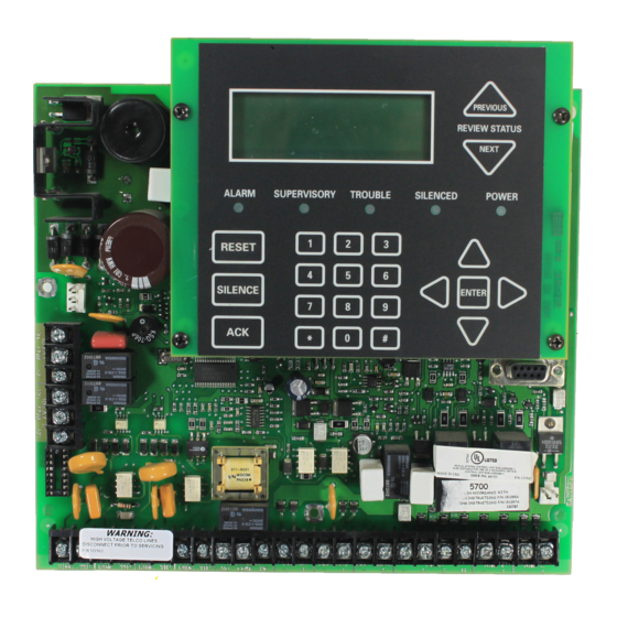
Before You Begin Installing 151295 Board Assembly Diagram On-board Annunciator 120 VAC, 60 Hz, 1.5A AC Power Input Programming Port Form C Relays Terminal Block 1 Battery Connector Terminal Block 2 24 VDC Phone Lines SLC In/Out, NAC/Aux SLC Programming Power Circuits SBUS Form C... -
Page 22: Calculating Current Draw And Standby Battery
2.5 A. This is the maximum alarm current for the 5700 control panel. If the current is above 2.5 A you will need to use a notification power expander(s) such as the Silent Knight 5496 intelligent power module, to distribute the power loads so that the 5700 or the power expanders do not exceed their power rating. - Page 23 Before You Begin Installing 151295 Table 3-2: Current Calculation Worksheet for SK Devices # of Standby Alarm Device Current per Device Devices Current Current Standby/Alarm: 2 mA Standby: 2 mA SK-Beam-T (with integral test) Aux. Pwr Alarm: 8.5 mA (50 max.) Standby: .30 mA SK-FIRE-CO...
- Page 24 Model 5700 Installation Manual Table 3-2: Current Calculation Worksheet for SK Devices # of Standby Alarm Device Current per Device Devices Current Current B224BI Isolator Base (50 max.) Standby/Alarm: .5 mA Accessories Modules Standby 20mA 5860 Remote Fire Alarm (8 max) Annunciator Alarm 25mA...
-
Page 25: Current Draw Worksheet For Sd Slc Devices
Before You Begin Installing 151295 that can be drawn from the panel. 3. Use next size battery with capacity greater than required. 4. SK-Beam-T draws a maximum of 500mA from auxiliary power only when the test feature is used. This should be considered when determining auxiliary power capacity but not calculated into current requirements for day to day operation. - Page 26 Model 5700 Installation Manual Table 3-3: Current Calculation Worksheet for SD Devices # of Standby Alarm Device Current per Device Devices Current Current SD500-LIM (100 max.) (50 max.) Standby/Alarm .092 mA SD505-6IB Accessories Modules Standby: 20 mA 5860 Remote Fire Alarm (8 max.) Annunciator Alarm:...
-
Page 27: Maximum Battery Standby Load
Warning! Silent Knight does not support the use of batteries smaller than those listed in table above. If you use a battery too small for the installation, the system could overload the battery resulting in the installation having less than the required 24 hours standby power. - Page 28 Model 5700 Installation Manual See Sec. Task (for more info.) SLC Device Hardware Installation. Perform these steps before running JumpStart. Connect device bases to the loop. SK 5.5 SD 5.7 Set device addresses. SK 5.6 SD 5.7 Physically connect detectors to their bases. Connect relay and contact monitor modules. 5.4 &...
- Page 29 Before You Begin Installing 151295 See Sec. Task (for more info.) Output Point Configuration Conventional notification circuits (circuits 1-6): Enable circuits used for notification appliances through programming, if necessary. 7.4.1 (JumpStart enables circuits 1-6 as Notification.) Conventional relay circuits (circuits 7-8): Select options for relay circuits, if desired.
-
Page 30: Control Panel Installation
Control Panel Installation 151295 Section 4 Control Panel Installation Caution! To avoid the risk of electrical shock and damage to the unit, power should be OFF at the control panel while installing or servicing. Mounting the Control Panel Cabinet Read the environmental specifications in Section 3.2 before mounting the 5700 panel. The 5700 cabinet dimensions are: 12¾”... -
Page 31: Installing The Dead Front
Control Panel Installation 151295 4.1.3.1 Installing the Dead Front Follow these steps to properly install the dead front panel into the control panel cabinet. Remove the top two annunciator screws, do not discard them they will be reused. See Figure 4-1 for annun- ciator screw location. -
Page 32: Ac Connection
Model 5700 Installation Manual AC Connection At installation, connect the AC terminals to the power source as shown in Figure 4-2. It may be necessary for a professional electrician to make this connection. The AC terminals are rated at 120 VAC, 60 Hz, 1.5A. Supervised To AC Ground... -
Page 33: Battery Connection
Control Panel Installation 151295 Battery Connection The control panel battery charge capacity is 7.0 to 35 AH. The main control cabinet can house batteries up to 7 AH, larger capacity batteries can be housed in a Remote Battery Box (P/N RBB). See Section 4.3.1 for deteails.Use 12V batteries of the same AH rating. -
Page 34: Rbb Accessory Cabinet
Model 5700 Installation Manual 4.3.1 RBB Accessory Cabinet The Model RBB Accessory cabinet can be used when your backup batteries requirements use backup batteries that are too large to fit into the main control panel cabinet. The RBB cabinet holds batteries up to the 35 AH size. The RBB dimensions are 16"... - Page 35 Control Panel Installation 151295 Run extended battery cable from control panel cabinet through conduit to RBB cabinet. See Figure 4-6. RBB Cabinet Cover Screws Conduit Coupler Conduit RBB Cabinet Cover Screws Figure 4-6 Battery Connections in the RBB Cabinet Note: Figure 4-6 is an example of how the wire connections can be routed. However, any other cabinet knock- outs (on either the main control panel or the RBB cabinet), that are not previously being used may be uti- lized to connect conduit between the two cabinets.
-
Page 36: Sbus Wiring
Model 5700 Installation Manual SBUS Wiring This section contains information on calculating SBUS wire distances and the types of wiring configurations (Class B). 4.4.1 Calculating Wiring distance for SBUS modules The following instructions will guide you in determining the type of wire and the maximum wiring distance that can be used with control panel SBUS accessory modules. - Page 37 Control Panel Installation 151295 Note: The following formulas were used to generate the wire distance chart: 6.0 Volts Maximum Resistance (Ohms) = Total Worst Case Current Draw (amps) Maximum Resistance (Ohms) Maximum Wire Length (Feet) = * 500 (6000 feet maximum) where: Rpu = Ohms per 1000 feet for various wire gauges (see table below) Table 4-2: Typical Wire Resistance Per 1000 ft.
-
Page 38: Wiring Configurations
Model 5700 Installation Manual 4.4.2 Wiring Configurations Figure 4-8 illustrates Class B configuration. Supervised Power Limited Figure 4-8 SBUS Class B Wiring 4.4.2.1 How to Power SBUS Devices From Auxiliary Power Supply Figure 4-9 illustrates how to power SBUS devices from an Auxiliary Power Supply such as the 5495 or 5499, when the maximum number of SBUS devices exceeds the SBUS power requirements. -
Page 39: 5860Emote Annunciator Installation
Control Panel Installation 151295 5860 Remote Annunciator Installation The optional Model 5860 Remote Annunciator, shown in Figure 4-10, performs the same functions as the on- board annunciator as well as initiate and end fire drills with a single key press and view event history by alarms, supervisories, or troubles. -
Page 40: Mounting The 5860
Model 5700 Installation Manual 4.5.1 Mounting the 5860 This section of the manual describes mounting the remote annunciator. The annunciator can be flush- or surface- mounted. Figure 4-11 shows the parts of the annunciator. Instructions for disassembling and mounting appear on the following pages. - Page 41 Control Panel Installation 151295 The 5860 comes from the factory fully assembled. You must disassemble it for mounting. To disassemble the annunciator, use a 5/64 hex wrench to remove the set screws, located on the bottom of the annunciator bezel. (See Figure 4-12 for location of the set screws.) Holes for surface mounting.
-
Page 42: Flush Mounting
Model 5700 Installation Manual 4.5.1.1 Flush Mounting This section of the manual describes flush mounting. You can flush-mount with or without an electrical box. Flush Mounting with an Electrical Box The 5860 annunciator can be used with the following types of electrical boxes: 4S, single-gang, and double- gang. -
Page 43: Surface Mounting
Control Panel Installation 151295 After the annunciator wiring to the panel has been completed (described in Section 4.5.2), replace the elec- tronic assembly in the back box. Place the bezel over the back box and tighten the set screws on the bezel. Attach second set of wires to top of back box. -
Page 44: 5824 Serial/Parallel Printer Interface Module Installation
Model 5700 Installation Manual 5824 Serial/Parallel Printer Interface Module Installation The 5824 serial/parallel printer interface module allows you to connect a printer to the panel, so you can print a real-time log of system events, a report of detector status, and event history. 5824 installation involves the following steps: Make sure power is off at the panel. -
Page 45: Selecting 5824 Options
Control Panel Installation 151295 4.6.1 Selecting 5824 Options Configuring the 5824 includes the following steps: • Add the module to the system. JumpStart will add the module automatically (see Section 6.1). You can also add it manually (see Section 7.2.2). •... -
Page 46: 5880 Led Driver Module
Model 5700 Installation Manual 5880 LED Driver Module The 5880 is an LED driver board that can be used in a wide variety of applications, including as an interface with most customized floor plan annunciator boards. The 5880 can drive up to 40 LEDs and has one PZT controller. The 5880 also has eight inputs for dry contact monitoring. -
Page 47: Facp Connection
Control Panel Installation 151295 4.7.2 FACP Connection The 5880 connects to the panel via the SBUS. Make connections as shown in Figure 4-20. After the 5880 is connected to the panel, it must be added to the system. This programming step is described in Section Figure 4- Supervised Power Limited Figure 4-20 5880 Connection to Main Control Panel Assembly... -
Page 48: Led Wiring
Model 5700 Installation Manual 4.7.3 LED Wiring There are four 12-pin connectors on the 5880 board for connecting LEDs. Each LED gets its power from Pin 11. Internal resistors are sized so that there is approximately 10 mA of current for each LED, no series resistors are required. -
Page 49: 5865-3 / 5865-4 Led Annunciator Installation
Control Panel Installation 151295 inputs. Supervised Model 7628 4.7k EOL Figure 4-22 Dry Contact Wiring 5865-3 / 5865-4 LED Annunciator Installation The 5865-3 and 5865-4 are LED annunciators. The 5865-4 has 30 mappable LEDs, remote silence and reset key switches, and a general system trouble LED. The 5865-3 has 30 mappable LEDs only. These are arranged as 15 pairs of red (typically used for alarm) and yellow (typically used for trouble) LEDs. -
Page 50: Facp Connection
Model 5700 Installation Manual 4.8.1 FACP Connection The 5865 connects to the panel via the SBUS. Make connections as shown in Figure 4-24. After the 5865 is connected to the panel, it must be added to the system. This programming step is described in Section Figure 4- Supervised Power Limited Figure 4-24 5865 Connection to the FACP... -
Page 51: Configuring Modules
Control Panel Installation 151295 Slide the labels under the plexiglass as shown in Figure 4-26. The LEDs will show through the label when illuminated. Figure 4-26 Inserting Zone Description Labels Configuring Modules This section describes how to configure any system hardware modules that have been added to the system. 4.9.1 Assigning Module IDs When installing a hardware module (such as, 5824, 5860, 5496, 5865-3 or 5865-4), you must use the DIP... -
Page 52: Telephone Connection
Refer to Section 7.2 to edit, add, delete, and view module list. 4.10 Telephone Connection Connect the telephone lines as shown in Figure 4-28. The Model 7860 phone cord is available from Silent Knight for this purpose. A number of programmable options are available for customizing telephone lines. These options are described in Section 7.6. -
Page 53: Class B Notification Wiring
Control Panel Installation 151295 4.11.1.1 Class B Notification Wiring You must use an appliance from the list of compatible appliances in the Appendix A at the back of this manual. To install a Class B notification appliance circuit: Wire Class B Notification appliances as shown in Figure 4-29. Configure the circuit through programming (see Section 7.5). -
Page 54: Class A Notification Wiring
Model 5700 Installation Manual 4.11.1.2 Class A Notification Wiring You must use an appliance from the list of compatible appliances in the Appendix at the back of this manual. To install a Class A notification appliance circuit: Wire the Class A notification appliances as shown in Figure 4-30. Caution For proper system supervision do not use looped wire under terminals marked –... -
Page 55: Auxiliary Power Installation
Control Panel Installation 151295 4.11.2 Auxiliary Power Installation NAC Circuits 1and 2 on the control panel can be used as auxiliary power circuits. The four types of auxiliary power available are: • Door Holder (see section 4.11.2.1) • Constant (see section 4.11.2.2) •... -
Page 56: Constant Power
Model 5700 Installation Manual 4.11.2.2 Constant Power Use constant power for applications that require a constant auxiliary power source. Power is always present at Constant circuits. 4.11.2.3 Resettable Power Resettable power is typically used to power beam detectors, flame detectors and conventional 4-wire smoke detectors. -
Page 57: Remote Station Applications
Control Panel Installation 151295 4.13 Remote Station Applications 4.13.1 Keltron Model 3158 Installation The control panel is compatible with Keltron Model 3158, used for direct connection to a Keltron receiver. The 3158 reports alarms, supervisories, and troubles. The 3158 is intended for connection to a polarity reversal circuit of a remote station receiving unit having compatible ratings. -
Page 58: City Box Connection Using The 5220 Module
Model 5700 Installation Manual 4.13.2 City Box Connection Using the 5220 Module This section describes how to connect the control panel to a municipal fire alarm box or “city box” as required by NFPA 72 Auxiliary Protected Fire Alarm systems for fire alarm service. The city (master) box is an enclosure that contains a manually operated transmitter used to send an alarm to the municipal communication center which houses the central operating part of the fire alarm system. -
Page 59: Nfpa 72 Polarity Reversal
Control Panel Installation 151295 4.13.3 NFPA 72 Polarity Reversal 4.13.3.1 Using the 5220 Module When the 5220 is wired and programmed for polarity reversal, it reports alarm and trouble events to a remote site. Alarms will override trouble conditions and it will not be possible to reset the remote indicator until the condition is cleared and the control panel is reset. -
Page 60: Using The 7644-L8 Module
Model 5700 Installation Manual 4.13.3.2 Using the 7644-L8 Module When the 7644-L8 is used for polarity reversal, it allows alarm and trouble events to be reported to a remote site. Alarms will override trouble conditions and it will not be possible to reset the remote indicator until the condition is cleared and the control panel is reset. - Page 61 Control Panel Installation 151295 Wire the SD500-ARM as shown in Figure 4-37. Intended for Connection to a Polarity Reversal Circuit of A Remote Station Receiving Unit Having Compatible Rating. Supervised Power Limited UL Listed Note: UL Listed EOL must be permanently mounted UL Listed To Remote Receiving Station...
-
Page 62: Using A Mr-201/T Control Relay From Air Products
Model 5700 Installation Manual 4.13.5 Using a MR-201/T Control Relay From Air Products When the MR-201/T control relay is wired for polarity reversal, it reports alarm and trouble events to a remote site. Alarms will override trouble conditions and it will not be possible to reset the remote indicator until the condition is cleared and the control panel is reset. -
Page 63: Transmitter Activated By Dry Contacts
Control Panel Installation 151295 4.13.6 Transmitter Activated by Dry Contacts This section describes the connection of a UL 864 listed remote station transmitter to the 5700 FACP dry contacts. The FACP contacts must be supervised by the remote station transmitter module using end-of-line resistors (ELRs) with a value determined by the transmitter manufacturer. -
Page 64: Sk And Sd Slc Device Installation
SK and SD SLC Device Installation 151295 Section 5 and SD SLC Device Installation Caution! To avoid the risk of electrical shock and damage to the unit, power should be OFF at the control panel while installing or servicing. List of SK SLC Devices The following SK SLC devices can be used with the control panel. -
Page 65: List Of Sd Slc Devices
SK and SD SLC Device Installation 151295 Installation SK Part Number Model Name/Description Sheet PN B210LP 6" mounting base I56-0595-00 B224BI 6" isolator base I56-0725-00 B224RB 6" relay base I56-3737-00 B200SR 6" temporal sounder base I56-3392-00 B200S Intelligent Sounder Base I56-3387-00 B501 4"... -
Page 66: Maximum Number Of Devices
Model 5700 Installation Manual Maximum Number of Devices The 5700 supports SK or SD devices on one 5700system. The maximum number of devices per system varies depending on device protocol. Device support is as follows: • SK Devices–A5700 system can support a total of 50 SK detectors and 50 SK modules. •... - Page 67 SK and SD SLC Device Installation 151295 The following figures show how length is determined for out and back tap and T-Tap style wiring. Figure 5-1 Calculating wire run length for a simple out and back When using T-taps, the total length of all taps and the main bus must not exceed 40,000 feet. This requirement must be met in addition to the maximum distance requirements for the various wire gauges.
-
Page 68: Wiring Slc Devices In Style 6 & 7 (Class A)
Model 5700 Installation Manual 5.4.2 Wiring SLC Devices in Style 6 & 7 (Class A) Configuration The following figure illustrates how to wire the SLC loop for Style 6 or Style 7 Class A installations. Note: Style 6 does not use short circuit isolator devices. Figure 5-3 Class A SLC Configuration Note: No t-taps allowed on class A SLC loops. -
Page 69: Sk Detector Installation
SK and SD SLC Device Installation 151295 SK Detector Installation This section describes how to install heat and smoke detectors. All detectors ship with installation instructions. Refer to the detector’s installation instructions for more detailed information. This information applies to the following SK models: •... -
Page 70: Addressing Sk Slc Devices
Model 5700 Installation Manual Addressing SK SLC Devices All SK devices are addressed using the two rotary dials that appear on the device board. Use the ONES rotary dial to set the ones place in a one or two digit number, and use the TENS rotary dial to set the tens place in a two digit number. -
Page 71: Sd Detector Installation
SK and SD SLC Device Installation 151295 SD Detector Installation The information in this section applies to the following SD models: SD505-HEAT Heat Detector or SD505- PHOTO Photoelectric Smoke Detector. 5.7.1 Wiring SD Detectors Wire device bases as shown in Figure 5-6. Set the address for each device as described in Section 5.8. -
Page 72: Addressing Sd Slc Devices
Model 5700 Installation Manual Addressing SD SLC Devices This section tells how to address detectors and modules. 5.8.1 SD505-PHOTO or SD505-HEAT The SD505-PHOTO photoelectric smoke detector and SD505-HEAT heat detector are easily addressed at the FACP. The Installer Code is required to perform this task. To address a SD505-PHOTO or SD505-HEAT: Connect a detector base temporarily to the programming terminals as shown in Figure 5-7. -
Page 73: Slc Devices With Dip Switches
SK and SD SLC Device Installation 151295 5.8.2 SLC Devices with DIP Switches Input and relay module addresses are set using the DIP switches on the module board. The chart below shows the available addresses. For example, to select address 3, place DIP switches 1 and 2 in the up position. The range of valid addresses is 1-50. -
Page 74: Programming Overview
Programming Overview 151295 Section 6 Programming Overview This section of the manual is intended to give you an overview of the programming process. Please read this section of the manual carefully, especially if you are programming the control panel for the first time. The JumpStart feature automates many programming tasks and selects default options for the system. -
Page 75: Running Jumpstart
Programming Overview 151295 Assigned to Group 124. JumpStart automatically programs Zone 1 to activate Group 124 using constant on output when a supervisory condition occurs. Circuit 4 (Relay 2): Assigned to Group 125. JumpStart automatically programs Zone 1 to activate Group 125 using constant on output when an alarm occurs. -
Page 76: Mapping Overview
Model 5700 Installation Manual Mapping Overview This section of the manual is an overview of mapping. Details about how to select mapping options appear in the appropriate subsections in Section 7. Mapping is an important concept with the control panel. In general terms, mapping is assigning or linking events to outputs that should activate when events occur. -
Page 77: Input Point Mapping
Programming Overview 151295 6.2.1 Input Point Mapping Input points are assigned to input zones. Any input point can be assigned to any input zone. (Input points can be assigned to one zone only. An input point can be designated as “Unused,” which means it has not been assigned to a zone.) Figure 6-2 Input Point Assignment Example... -
Page 78: Output Circuit Mapping
Model 5700 Installation Manual 6.2.2 Output Circuit Mapping Figure 6-3 is a simple example showing how to assign notification and relay output circuits to groups. For an example of a simple floor above/floor below application, see Figure 6-5. Figure 6-3 Assigning Output Circuits to Groups (Example) -
Page 79: Zone Event Mapping
Programming Overview 151295 6.2.3 Zone Event Mapping There are 11 types of events that can occur in zones (see below). For each event type, you can activate up to 8 output groups and patterns. If it is necessary to map to more than 8 output groups, an output group template may be used (see Section 7.4.5 for information on output group templates). - Page 80 Model 5700 Installation Manual Figure 6-5 Example of Zone Events Mapped to Output Groups and Patterns...
-
Page 81: Mapping Led Points
Programming Overview 151295 6.2.4 Mapping LED Points Figure 6-6 is a simple example showing how LED points are mapped to zones and output groups. Typically you would create two output groups for each zone, one for alarms and one for troubles. (LED points are available when Models 5865-3/4 and/or 5880 are used with the system). -
Page 82: Programming Using The 5660 Silent Knight Software Suite
SKSS is an optional software package that lets you easily program the control panel using a Windows-based computer and a modem* (not sold by Silent Knight). When using SKSS, you can set up the programming options for the panel, save the options in a file, then download the file to the panel. You connect to the control panel directly using the control panel’s onboard serial port or remotely using a modem. -
Page 83: Moving Through The Menus
Programming Overview 151295 6.4.2 Moving through the Menus Figure 6-7 shows how to move through Menu screens, using the System Options screen as an example. Figure 6-7 Moving through Program Menu 6.4.3 Selecting Options and Entering Data There are several ways to make programming selections using the control panel depending on which screen you are currently using. -
Page 84: Editing Keys
Model 5700 Installation Manual 6.4.4 Editing Keys The keys shown in Figure 6-8 are available for use when you are in the Program Menu. Figure 6-8 Editing Keys Available from Program Menu 6-11... -
Page 85: Programming Menu Quick Reference
Programming Overview 151295 Programming Menu Quick Reference This section of the manual lists all Program Menu options in the order they appear on the sub-menus. Default settings are indicated in text or marked with an asterisk. The comments column provide quick information and a reference to a section (if applicable) which has more detailed information. - Page 86 Model 5700 Installation Manual Menu Options/Defaults Comments SD Devices. Cadence 00-16, 23, *02 Section 7.3.1.4 Section 7.3.1.5 Edit Zone Select Zone to Edit Zone Accessry Opt Fire Cadence 00, 01, *02, 23 SK Devices. Section 7.3.1.4 CO Cadence 00, 01, 02, *23 Section 7.3.1.5 Local Zone Y or *N...
- Page 87 Programming Overview 151295 Menu Options/Defaults Comments UNUSED *Latching (LA) or Non-Latching (NL) *Silenceable (SI) or Non- Silenceable (NS) Zone # (*001) PHOTO, ION, ACCESSORY, HEAT, SDR BAS, RLY ACCLIMATE, BAS, I-SdrBa HEAT HT, PHOT- HEAT, BEAM Single/Multi Station: *NST, SST, MST Station Silenceable: *SIL, Accessory Group...
- Page 88 Model 5700 Installation Manual Menu Options/Defaults Comments *Latching (LA) or Non-Latching (NL) *Silenceable (SI) or Non- Silenceable (NS) Zone # (*001) PHOTO, ION, ACCESSORY, HEAT,ACCLIMAT SDR BAS, RLY E, HEAT HT, PHOT-HEAT, BAS, I-SdrBa BEAM Single/Multi Station: *NST, SST, MST Station Silenceable: *SIL, Accessory Group...
- Page 89 Programming Overview 151295 Menu Options/Defaults Comments *Latching (LA) or Non-Latching (NL) *Silenceable (SI) or Non- Silenceable (NS) Zone # (*001) ALRM Fire/ALRM ACCESSORY, CO, ALRM Fire/ SDR BAS, RLY SUPR CO, Sensor Point # CO FIRE BAS, I-SdrBa SUPR Fire/ALRM CO, SUPR Fire/ Single/Multi SUPR CO...
- Page 90 Model 5700 Installation Manual Menu Options/Defaults Comments AUX CONST, AUX RESET, Point Name AUX DOOR Group # (*001) OUTPUT PT Point Name RELAY Internal and Section 7.5.1 AUX RESET, External 5815XL, Module Point # Point Name AUX DOOR SK Devices *Silenceable (SI) or Non- Silenceable (NS)
- Page 91 Programming Overview 151295 Menu Options/Defaults Comments *Latching (LA) or Non-Latching (NL) *Silenceable (SI) or Non- Silenceable (NS) Zone # (*001) ACCESSORY, SDR BAS, RLY PHOTO, ION, HEAT Single/Multi Station: *NST, SST, MST SUP DET Station Silenceable: *SIL, Accessory Group # (*001) Point Name *Latching (LA) or Non-Latching...
- Page 92 Model 5700 Installation Manual Menu Options/Defaults Comments *Latching (LA) or Non-Latching (NL) SYS_AUX1, *Silenceable (SI) SYS_AUX2 or Non- Silenceable (NS) Point Name Zone # (*001) Used to activate an ancillary Output Group that does not activate alarm, sound PZT, STATUS PT display status or Point Name report events.
- Page 93 Programming Overview 151295 Menu Options/Defaults Comments *Silenceable (SI) FIREDRILL, or Non- SILENCE, Silenceable (NS) RESET Point Name *Latching (LA) or Non-Latching Section 7.5.2 (NL) SYS_AUX1, *Silenceable (SI) SUS_AUX2 or Non- Silenceable (NS) Point Name B SWITCH Zone # (*001) Used to activate an ancillary Output Group that does not...
- Page 94 Model 5700 Installation Manual Menu Options/Defaults Comments *Latching (LA) or Non-Latching (NL) SYS_AUX1, SUS_AUX2 *Silenceable (SI) 5880 SWITCH or Non- Point Silenceable (NS) Point # Section 7.5.3 (cont.) Zone # (*001) STATUS PT Point Name UNUSED 5865 Group # (*001) NOTIF OUT, NOTIF CTRL CKT...
- Page 95 Programming Overview 151295 Menu Options/Defaults Comments Account # (6- digit number, identifies Edit Account # *123456 account to central station) Section 7.6.1.1 Reporting Format (SIA, Edit Format *CID, S20, SIA SIA20, Contact ID) Section 7.6.1.1 Yes (Y), *No (N), Report Alarms or Must (M) Choose Account Rep.
- Page 96 Model 5700 Installation Manual Menu Options/Defaults Comments Select Group System Trouble None selected Select Cadence Select Group Alarm Silence None selected Select Cadence Select Group Trbl Silence None selected Select Cadence Group Tr SBUS Com SBUS Pwr Trouble Events Section 7.6.3.1 SLC Loop AC Loss Select Group...
- Page 97 Programming Overview 151295 Menu Options/Defaults Comments System Daylight Savings *Yes (Enabled) or Automatic Options No (Disabled) Daylight Saving Time enable or (cont.) disable. Section 7.6.6.1 DST Start Select week: 1st, Select month Section 7.6.6.2 *2nd, 3rd, 4th or (*Mar) Last DST End Select week: *1st, Select month...
- Page 98 Model 5700 Installation Manual Menu Options/Defaults Comments Access Select Profile Edit Name Profile 1 is the profile that dictates Codes what functions the Firefighter Key (01-20) Edit Access Code has access to. Because this is the Panel Functions System Reset profile for a key the user name and System Silence the access code can not be edited...
-
Page 99: Programming
This section of the manual describes how to manually program the control panel from the built-in annunciator. Each subsection discusses these menu options in detail. All options described in this section can be performed using the Silent Knight Software Suite 5660. Important! Before any customized programming is done, JumpStart should be run first. -
Page 100: Modules
Programming 151295 Modules This section lists the options available under the module option in the program menu. The types of modules available for the control panel are, 5860 (Keystation) 5824 (Serial/Parallel input/output), 5880 (LED Input/ Output module), 5496 (Intelligent Power Module), and a 5865 (LED Annunciator). 7.2.1 Edit Modules The features that can be edited when this option is selected are, module name, and class of wiring (Class A or... -
Page 101: Deleting A Module
Model 5700 Installation Manual Select 7 for Program Menu. Press 1 to enter module menu. Press 2 to add a module. From the next screen, use the arrow to choose a module type to add from the <New Module Type> screen. -
Page 102: Edit Zone Name
Programming 151295 7.3.1.1 Edit Zone Name To edit the zone name, press 1. A screen similar to the one shown in Figure 7-2 displays. Figure 7-2 Selecting Character for Zone Name Select the characters for the zone name by pressing the arrow until the desired character is shown then press . - Page 103 Model 5700 Installation Manual Alarm Delay Characteristics Select the alarm delay characteristics by pressing the arrow. Table 7-1 list the delay choices and a description of each. Table 7-1: Alarm Delay Types Type of Delay Description 1-Count One Count (No Delay). When this option is enabled, an alarm occurs immediately when a single device of any of the following types goes into alarm: detector, manual pull, water flow, Aux1 or Aux2.
-
Page 104: Zone Outputs
Programming 151295 Heat Temperature Setting Use this feature to set the temperature at which high temperature detectors will respond. All detectors in the zone will respond in the same way. The range for the SD505-HEAT heat detector is from 135°F to 150°F. The range for SK-Heat-HT heat detector is from 135°F to 190°F. - Page 105 Model 5700 Installation Manual Select options for each event that could occur in this zone. Figure 7-4 is a complete example of how you might map a zone. Indicates output group 1, cadence pattern 00 has been selected. 00 is a constant output cadence.
-
Page 106: Cadence Patterns
Programming 151295 7.3.1.4 Cadence Patterns The cadence patterns shown in Figure 7-6 are available for use with the control panel. Cadence patterns can be selected by event type for each zone or for the entire system. Special cadence patterns can be selected for fire drills and any auxiliary system switches used with the system. Figure 7-6 Cadence Patterns Available with the Control Panel Note: When select cadence patterns for alarms, supervisories, or troubles they must be distinctive from each other. -
Page 107: Zone Accessory Options
Model 5700 Installation Manual 7.3.1.5 Zone Accessory Options This option applies to detectors that are used with Sounder bases and Relay bases. Fire Cadence:_ _ / CO Cadence:_ _ (choose from a subset of Patterns 00 to 23). Note: The B200S Sounder bases is intended to be used along with the CO Cadence setting. Local Zone (choose Y (Yes) or N (No). -
Page 108: Group
Programming 151295 Enter the number of the zone you wish to view, then press ENTER Zone Number Module or Device Address Point Number Total Number of Points in the Zone Figure 7-7 View Zone Points Screen Group An output group is made up of output points that have been programmed to respond in the same way. Output groups simplify programming because you do not have to program each individual point. -
Page 109: Edit Group Properties
Model 5700 Installation Manual 7.4.1.2 Edit Group Properties The Edit Group Menu allows you to select options for each group for the following items: Follow steps 1 through 5 of Section 7.4.1. To edit the group properties, press 2. • Latching or non-latching outputs. - Page 110 Programming 151295 Silencing Options The following silencing options are available for each output group. Table 7-2: Silencing Options Option Description SILENCE Silenceable. The output group can be silenced through the SILENCE key. NON-SIL Not silenceable. The output group cannot be silenced. Activation of the SILENCE key will be ignored for this output group.
-
Page 111: Add Group
Model 5700 Installation Manual 10. Press ENTER 11. Repeat steps 14 and 15 for all the activation options. 7.4.2 Add Group To add a group, follow these steps: Enter the installer code. Select 7 for Program Menu. Press 3 to enter group menu. Press 2 to add a group. -
Page 112: Edit Output Group Templates
Programming 151295 7.4.5 Edit Output Group Templates Some installations may require that zones be mapped to more than 8 output groups. With output group templates you can combine one or all output groups into one template, which can be used when the same combination of outputs are used for several zones. -
Page 113: Point
Model 5700 Installation Manual Point You may need to change characteristics of individual input points (detectors and switches) even after using JumpStart. This section explains how to change options for: type of point, latching/non-latching, silenceable/ non-silenceable, zone assignment (input points), detector accessory base options, group assignment (output points), and point name. - Page 114 Programming 151295 Table 7-4: Point Programming Type Latching Module Type Function Comments Selection Option SUP PHOTO DUCT SUP SMOKE PHOTO SUP SMOKE SUP HEAT Latching SK SUP Supervisory switches can be latching or non-latching. DETECTOR Non Latching ACCLIMATE SUP HEAT HT SUP SMOKE PHOTO/HEAT SUP SMOKE...
-
Page 115: Point Programming For Internal Or External Power Module
Model 5700 Installation Manual Table 7-4: Point Programming Type Latching Module Type Function Comments Selection Option Use this switch type for tamper monitoring of sprinklers Latching and other fire protection devices. If a contact closes, a SUPERVSY sprinkler supervisory event will be generated. Non Latching Supervisory switches can be latching or non-latching. - Page 116 Programming 151295 Enter the installer code. Select 7 for Program Menu. Press 4 to enter point menu. Press the arrows to select the desired module. Press . Refer to Section 6.5 for available ENTER choices. Enter the number of the circuit or point you wish to edit. Refer to Table 7-6 for available selections. Press ENTER Select the type by pressing the...
- Page 117 Model 5700 Installation Manual 11. Repeat Steps 1 through 15 for all circuits. Table 7-5 Menu choices for Internal/External Power Modules Function Choices Type Selections Selections for Comments each Type Enter Point or Circuit UNUSED NOTIF OUT CTRL CKT AUX PWR CONSTANT Constant auxiliary power.
-
Page 118: Point Programming For 5880 And 5865 Modules
Programming 151295 7.5.3 Point Programming For 5880 and 5865 Modules To program for a 5880 or 5865 module points, follow these steps: Enter the installer code. Select 7 for Program Menu. Press 4 to enter point menu. Press the arrows to select the desired module. Refer to Section 6.5 for available choices. Press ENTER Figure 7-11 Programming Points Screen for 5880 and 5865 Modules... -
Page 119: System Options
Model 5700 Installation Manual A screen similar to the one shown in Figure 7-12 displays. Figure 7-12 Selecting Character for Zone Name Select the characters for the point name by pressing the arrow until the desired character is shown then press the right arrow Enter the Numerical Designator for the character you want, then press . - Page 120 Programming 151295 each field. Figure 7-13 Reporting Account Editing Screen Select Account (ID) The control panel provides up to 4 reporting accounts. The priority of an account is based on its account ID. Account 1 is highest priority; Account 4 is lowest. Use Account 1 to report the highest priority events. Press the arrow to select account ID number, then press ENTER...
- Page 121 Model 5700 Installation Manual 10. Repeat step 9 for all five event report options. For each event family, select M, Y, or N. M(ust) Must Report. Selecting "M" makes this a primary reporting account for this family of events. The dialer MUST report events in this family to this account.
-
Page 122: Auto Test Time
Programming 151295 7.6.1.2 Auto Test Time To access the automatic dialer test time screen: Enter the installer code. Select 7 for Program Menu. From the Program Menu, select 5 for System Options. From the next menu, select 1 for Reporting Account. From the next menu, select 2 for Auto Test Time. -
Page 123: Dialing Prefix
7.6.2.2 Number of Answer Rings This option is used in conjunction with the Silent Knight Software Suite 5660. Use the option to determine the number of rings before the panel answers a call from the computer. Range is 00-15 rings. This option is factory- programmed as 06 rings, which should be compatible for most installations where the answering machine bypass feature is used. -
Page 124: Answering Machine Bypass
151295 7.6.2.6 Answering Machine Bypass This option is used in conjunction with the Silent Knight Software Suite 5660. This feature ensures that an answering machine will not interfere with communication between the panel and the computer. If an answering machine is used at the panel site, enable this feature; if an answering machine is not used, disable the feature. -
Page 125: System Alarm Cadence
Model 5700 Installation Manual Figure 7-16 System Trouble Event Mapping Example 7.6.3.2 System Alarm Cadence Fire drill and system auxiliary alarm events can have special cadence patterns to distinguish them from other types of alarms. See Section 7.3.1.4 for available cadence patterns. A typical use of the System Aux1 and Aux2 patterns is to distinguish fire emergencies from other types of emergencies. -
Page 126: Water Flow Delay
Programming 151295 7.6.4.1 Water Flow Delay You can program a delay of 0-90 seconds (zero means no delay) to be used in conjunction with a water flow switch. The delay is system-wide. All water flow switches on the system will use the same delay period. To access the screen for programming water flow delay, follow these steps: Enter the installer code. -
Page 127: Change Ac Line Frequency
Model 5700 Installation Manual Select AMPM (for AM/PM display format) or MIL (for military or 24 hr display format) by pressing the arrow, then press ENTER 7.6.4.5 Change AC Line Frequency The panel’s AC line frequency is selectable for 60 Hz or Neither. AC Frequency feature dictates how the control panel will calculate time based on the AC line frequency used in the installation site. -
Page 128: Single Key Acknowledge
Programming 151295 7.6.5.4 Single Key Acknowledge When this feature is programmed Y (Yes) allows the user to press the ACK Key and display the oldest un- acknowledged event in the system. Pressing ACK again will acknowledge the event, then display the next oldest un-acknowledge event without pressing the arrow keys. -
Page 129: Slc Family
Model 5700 Installation Manual up to 40 characters, two lines of 20 characters each. If you do not create a customized message, the system will use the internal banner. You cannot change the internal banner. To customize the banner display message: Enter the installer code. -
Page 130: Jumpstart Autoprogramming
Programming 151295 JumpStart Autoprogramming IMPORTANT! JumpStart is intended to be used prior to performing any custom programming. Each time JumpStart is executed, all options will be reset to their default values. Do not run JumpStart after you have configured the system through programming. To run JumpStart: Enter the installer code. -
Page 131: Access Codes
Model 5700 Installation Manual Access Codes Access codes provide the user access to the control panel functions. Each access code can be customized for each user. This allows some users the ability to access programming and other higher level panel functions, while other users may only need access to lower level functions such as preforming fire drills, or acknowledging trouble conditions. -
Page 132: Profile Edit Menu
Programming 151295 To change an access code: Enter the installer code. Select 7 for Program Menu. Select 8 for Access Codes. Display reads: Select Profile 01 Fire Fighter’s Key Select the access code you wish to edit by pressing the arrow. -
Page 133: System Operation
System Operation 151295 Section 8 System Operation Operation of the control panel is simple. Menus guide you step-by-step through operations. This section of the manual is an overview of the operation menus. Please read this entire section carefully before operating the panel. -
Page 134: Menu System
These options are described in detail in Section 7. 8- System Info View system information, including model and serial numbers and revision number and date. 9- Up/Download Initiate communication from the panel site between the panel and a computer running the Silent Knight Software Suite. -
Page 135: Using The Menus
Model 5700 Installation Manual 8.3.2 Using the Menus To move through the menus: to move through the options in a menu. Use to move to a previous menu. To select an option: Enter the number of the option. –OR– Press ENTER if the option appears at the top of the menu (= symbol displays after the option number in this case). -
Page 136: View Event History
System Operation 151295 to move through the list. Press to select the module where the point you want to dis- ENTER able/enable is located. Select the point to disable or enable on the module. A description of the point should display. -
Page 137: Conduct A Dialer Test
Model 5700 Installation Manual Select 3 for Walk Test-No Rpt. The LCD will display “WALK TEST STOPPED” on Line 1 and “ENTER = start test” on Line 3. If you select this option, central station reporting will be disabled while the test is in progress. -
Page 138: View Status Of A Point
System Operation 151295 Press 2 for Point Status. Select the module where the point you want to check is located. Enter the number of the point you want to check and press ENTER A screen similar to those shown in Figure 8-3 will display. Figure 8-3 Checking Detector Sensitivity Compliance If a printer is attached to the system (via a Module 5824 Serial/Parallel Interface), you can print detector status (see Section 8.4.19). -
Page 139: Reset Dialer
Model 5700 Installation Manual 8.4.17 Reset dialer From the Main Menu, select 6. The LCD will display “Dialer reset in progress... ” You will be returned to the Main Menu when the reset is completed. 8.4.18 Communicating with a Remote Computer An installer at the panel site can initiate communications between the panel and a computer running the Silent Knight Software Suite. -
Page 140: Working With A Printer
System Operation 151295 8.4.19 Working with a Printer If you are using the Model 5824 Serial/Parallel Interface, several printing options are available. See Section 4.6 for information about installing the 5824. From the Main Menu, select 5 Printer Options. From the next screen, select the 5824 module where the printer is connected. If the printer is not currently busy printing another report, a screen with the following options will be avail- able. -
Page 141: Operation Mode Behavior
Model 5700 Installation Manual Operation Mode Behavior The control panel can be in one of seven conditions at any given moment: Normal, Alarm, Prealarm, Supervisory, Trouble, Silenced, and Reset. Table 8-1 describes the behavior of the panel in each of these modes. Table 8-1: Operation Modes of FACP Operation Occurs... - Page 142 System Operation 151295 Table 8-1: Operation Modes of FACP Operation Occurs System Behavior In This Mode You Can Mode When Supervisory The system The dialer seizes control of the phone line Press down arrow to view the supervisory detects a and calls the central station.
- Page 143 Model 5700 Installation Manual Table 8-1: Operation Modes of FACP Operation Occurs System Behavior In This Mode You Can Mode When Trouble A system The dialer seizes control of the phone line Press down arrow to view the trouble. A trouble and calls the central station.
-
Page 144: Releasing Operations
System Operation 151295 Table 8-1: Operation Modes of FACP Operation Occurs System Behavior In This Mode You Can Mode When Reset The RESET All LEDs are on briefly then the LCD Menus are not available during the reset button is displays “ALARM RESET IN PROGRESS”. -
Page 145: Single Interlock Zone Releasing
Model 5700 Installation Manual Table 8-2: Approved Releasing Solenoids Manufacturer Part Number Rating T8210A107 24 VDC, 2.5A Asco 8210G207 24 VDC, 2.5A *When ordering request PN The Model 7641-L8 7641-L8 Must be located at the solenoid. Figure 8-4 Wiring Configuration for Solenoid Important! Detectors must be installed at 0.7 times the linear spacing as described in NFPA 72. -
Page 146: Double Interlock Zone Releasing
System Operation 151295 Conditions required for an General Alarm and Release Output Activation If two or more addressable detectors, or a manual release switch activate, the “Alarm” and the “Release” outputs will activate. (Also refer to Table 8-3.) Table 8-3: Input Conditions and Output Results Inputs Output Results 1st Addressable Detector... - Page 147 Model 5700 Installation Manual Conditions Required for a Release Output Activation Any release requires the activation of an interlock switch, and either a manual release switch or 2 activated addressable detectors. When these conditions are met, the “Release” and “General Alarm” outputs will activate, and the “Alert”...
-
Page 148: Smoke Alarm Verification
System Operation 151295 Smoke Alarm Verification Figure 8-5 illustrates how the Smoke Alarm Verification cycle operates. Figure 8-5 Smoke Verification Cycle During the Confirmation Period if there is no alarm indication then the system will return to normal operation. 8-16... -
Page 149: Reporting
SIA and Contact ID formats. Receivers Compatible with the Control Panel The below table shows receivers compatible with the control panel. Manufacturer Model Format Silent Knight Model 9800 SIA and Contact ID Model 9000 (SIA formats) Ademco Model 685 (Contact ID ) - Page 150 Reporting 151295 SIA Reporting Format Contact ID Reporting Format Module Event Parameter (if Event Group Contact Event Description ID # Event Qualifier Family any) Code (if any) Code Local Programming begin Trouble Local Programming ended normally Trouble Local Programming aborted or Trouble ended with errors Panel Date has been changed...
- Page 151 Model 5700 Installation Manual SIA Reporting Format Contact ID Reporting Format Module Event Parameter (if Event Group Contact Event Description ID # Event Qualifier Family any) Code (if any) Code Trouble Exp. ID Exp. ID Voice VBUS Trouble Restore Trouble Exp.
- Page 152 Reporting 151295 SIA Reporting Format Contact ID Reporting Format Module Event Parameter (if Event Group Contact Event Description ID # Event Qualifier Family any) Code (if any) Code Water release circuit has been Trouble pi Exp. ID Point # Exp. ID Point # disabled Water release circuit has been re-...
- Page 153 Model 5700 Installation Manual SIA Reporting Format Contact ID Reporting Format Module Event Parameter (if Event Group Contact Event Description ID # Event Qualifier Family any) Code (if any) Code Notification Trouble Trouble 1000+Group Group # Notification Output trouble restore Trouble 1000+Group Group #...
- Page 154 Reporting 151295 SIA Reporting Format Contact ID Reporting Format Module Event Parameter (if Event Group Contact Event Description ID # Event Qualifier Family any) Code (if any) Code Zone-based AUX1 switch trouble Trouble 1000+ Zone # 3 Zone # restore Zone-based AUX2 switch trouble Trouble 2000+ Zone # 3...
- Page 155 Model 5700 Installation Manual SIA Reporting Format Contact ID Reporting Format Module Event Parameter (if Event Group Contact Event Description ID # Event Qualifier Family any) Code (if any) Code Trouble pi Exp. ID Point # Exp. ID Point # Emergency NAC Trouble Restored Trouble pi Exp.
- Page 156 Reporting 151295 SIA Reporting Format Contact ID Reporting Format Module Event Parameter (if Event Group Contact Event Description ID # Event Qualifier Family any) Code (if any) Code Positive Alarm sequence Trouble pi Exp. ID Point # Exp. ID Point # acknowledge switch trouble Point Enabled Disable...
- Page 157 Model 5700 Installation Manual SIA Reporting Format Contact ID Reporting Format Module Event Parameter (if Event Group Contact Event Description ID # Event Qualifier Family any) Code (if any) Code Disable pi Exp. ID Point # Exp. ID Point # Voice Aux Status Switch Disabled Disable pi Exp.
-
Page 158: Testing And Troubleshooting
This section of the manual offers suggestions for troubleshooting hardware problems. Please read this section if you encounter a problem when installing the control panel. If these suggestions do not solve your problem or if you encounter a problem that is not listed here, contact Silent Knight Technical Support for assistance. 10.2 Common Problems... -
Page 159: Periodic Testing And Maintenance
Testing and Troubleshooting 151295 Problem Possible Cause / Suggested Actions 5496 module that has been physically Check the status of the 5496 green LED. If it flashes in the pattern .5 sec. on / .5 connected to the panel but is not being sec. -
Page 160: Built-In Troubleshooting And Testing Tools
Model 5700 Installation Manual 10.3 Built-in Troubleshooting and Testing Tools The fire control panel has several built-in testing and troubleshooting tools that can be utilized to save time while testing and troubleshooting points and SLC devices. 10.3.1 SLC Device Locator SLC device locator can be used to locate a device on a SLC loop. -
Page 161: I/O Point Control
Testing and Troubleshooting 151295 Press the arrow to toggle NO to YES then press ENTER If NO is chosen you will exit back to the Point Function menu. If Yes is chosen the system will cease normal operation leaving the premise unprotected. Select the SLC loop. -
Page 162: Installation Records
Installation Records 151295 Section 11 Installation Records This section of the manual is for you to use if you wish to track of how points, zones, and groups have been programmed. 11.1 Detector and Module Point Record You can use Table 11-1 to keep track of module and sensor points. Default addresses for ID: On-board: = 33 Table 11-1: Detector/Module Installation Record... -
Page 163: Appendix A Compatible Devices
Compatible Devices 151295 Appendix A Compatible Devices Table A-1: Compatible Notification Appliances Manufacturer Model Audio Visual Type SH24W-153075 Horn/Strobe SAD24-153075 Strobe SAD24-75110 Strobe SL24W-75110 Strobe SL24C-3075110 Strobe SLB24-75 Strobe RSD24-153075 Strobe RSD24-75110 Strobe SH24W-75110 Horn/Strobe AMSECO SH24W-3075110 Horn/Strobe SHB24-75 Horn/Strobe SCM24W-153075 Chimes/Strobe SCM24W-75110... -
Page 164: Appendix A Compatible Devices
Compatible Devices 151295 Table A-1: Compatible Notification Appliances Manufacturer Model Audio Visual Type Vibrating Bell Vibrating Bell Single Stroke Bell 2700 -M. -R, -T, -Y, -Z Strobe 2701 Series Strobe 2705 Series Strobe 2820 Snyc Temporal Horn/Strobe 2821 Snyc Temporal Horn/Strobe 2824 Horn Strobe 5333... - Page 165 Model 5700 Installation Manual Table A-1: Compatible Notification Appliances Manufacturer Model Audio Visual Type 5378 8-Tone Horn/Strobe 5383 8-Tone Horn/Strobe with Sync Strobe 5386 8-Tone Horn/Strobe with Sync Strobe 5387 8-Tone Horn/Strobe with Sync Strobe 5388 8-Tone Horn/Strobe with Sync Strobe 5508 Single Gang Sync Strobe 5509...
- Page 166 Compatible Devices 151295 Table A-1: Compatible Notification Appliances Manufacturer Model Audio Visual Type BLVCH Vibrating Chime H12/24-FC Horn H12/24W-FC Horn H12/24K-FC Horn HC12/24-FC Horn HC12/24W-FC Horn HC12/24K-FC Horn P2415-FC Horn/Strobe P2415W-FC Horn/Strobe P2415K-FC Horn/Strobe P241575-FC Horn/Strobe P241575W-FC Horn/Strobe P241575F-FC Horn/Strobe P241575K-FC Horn/Strobe P2430-FC...
- Page 167 Model 5700 Installation Manual Table A-1: Compatible Notification Appliances Manufacturer Model Audio Visual Type HG124 Horn HS24-15 Horn/Strobe HS24-30 Horn/Strobe HS24-60 Horn/Strobe HS24-75 Horn/Strobe HS24-110 Horn/Strobe HS24-1575 Horn/Strobe GCC24 Multi Candella Horn/Strobe Ceiling Mount GCCR24 Multi Candella Horn/Strobe Ceiling Mount GCS24 Multi Candella Strobe Ceiling Mount GCSR24...
- Page 168 Compatible Devices 151295 Table A-1: Compatible Notification Appliances Manufacturer Model Audio Visual Type Chime Chime CHSR 2-Wire Chime/Strobe CHSW 2-Wire Chime/Strobe Horn Horn Horn Horn WHT Wall 4x4 Horn Red Wall 4x4 HGRL Horn Red Wall 2x4 HGWL Horn WHT Wall 2x4 CHWL Chime WHT Wall 4x4 CHRL...
- Page 169 Model 5700 Installation Manual Table A-1: Compatible Notification Appliances Manufacturer Model Audio Visual Type P2WH-P 2-Wire Horn/Strobe High Candela PC2WH 2-Wire Horn/Strobe High Candela PC2WH-P 2-Wire Horn/Strobe High Candela P2RK 2-Wire Horn/Strobe PC2RK 2-Wire Horn/Strobe P2RHK 2-Wire Horn/Strobe High Candela PC2RHK 2-Wire Horn/Strobe High Candela 4-Wire Horn/Strobe...
- Page 170 Compatible Devices 151295 Table A-1: Compatible Notification Appliances Manufacturer Model Audio Visual Type Strobe SCRK Strobe SRHK Strobe High Candela SCRHK Strobe High Candela SRL, SRL-P, SRL-SP* Strobe Red Wall 4x4 SWL, SWL-P, SWL-ALERT Strobe White Wall 4x4 SWL-CLR-ALERT* SCRL Strobe Red Ceil 4x4 SCWL Strobe White Ceil 4x4...
- Page 171 Model 5700 Installation Manual Table A-1: Compatible Notification Appliances Manufacturer Model Audio Visual Type AH-12 Horn AH-24 Horn AH-12WP Horn Weatherproof AH-24WP Horn Weatherproof AMT-241575W Multi-Tone Horn Strobe AMT-24MCW Mutli-Tone Horn Strobe AMT-241575W-NYC Multi-Tone Horn Strobe AMT-12/24 Multi-tone Horn AMT-12/24 NYC Multi-tone Horn AS-121575W Horn/Strobe...
- Page 172 Compatible Devices 151295 Table A-1: Compatible Notification Appliances Manufacturer Model Audio Visual Type HS-24 Horn HS4-241575W Horn/Strobe HS4-24MCW Horn/Strobe HS4-24MCWH Horn/Strobe HS4-24MCC Horn/Strobe MIZ-24S Mini Horn Strobe MT-121575W MultitoneHorn Strobe MT-241575W Multitone Horn Strobe MT-24MCW Multitone Horn Strobe MTWP-2475W Multitone Horn Strobe MTWP-2475C Multitone Horn Strobe MTG-121575W...
- Page 173 Model 5700 Installation Manual Table A-1: Compatible Notification Appliances Manufacturer Model Audio Visual Type RSSR-2475W Strobe RSSR-2475C Strobe RSSR-24110C Strobe RSSA-24110W Strobe RSSB-24110W Strobe RSSG-24110W Strobe RSSR-24110W Strobe RSSA-24MCC Multi-Cd Strobe RSSB-24MCC Multi-Cd Strobe RSSG-24MCC Multi-Cd Strobe RSSR-24MCC Multi-Cd Strobe RSSWPA-2475W Strobe Weatherproof RSSWPA-24MCCH...
- Page 174 Compatible Devices 151295 table is organized by manufacturer. The columns show the number of detectors per loop that can be used. Identifier Operating Voltage Range 18.5–27.4 VDC Note: The maximum number of smoke detectors per zone is determined by both the current draw and the impedance of the smoke detector.
- Page 175 Model 5700 Installation Manual Table A-2: Compatible Two-Wire Smoke Detectors Model Name or Number Compatibility ID Manufacturer (Base model name or number # per Loop Head Base in parentheses.) 429C (S10A) S10A 30 / loop 429CRT (S11A) S11A 30 / loop 429CST (S11A) S11A 30 / loop...
- Page 176 Compatible Devices 151295 Table A-2: Compatible Two-Wire Smoke Detectors Model Name or Number Compatibility ID Manufacturer (Base model name or number # per Loop Head Base in parentheses.) 1400 20 / loop 1451 (B401B) 20 / loop 2100 20 / loop 2100T 20 / loop 2151 (B401)
-
Page 177: Appendix B Special Characters Lists
Special Characters Lists Appendix B Special Characters Lists This section contains tables of programmable characters that may be used for device, module, and zone names or phone numbers. Characters used for Naming Table B-1 list the available character and their associated numeric designator. When programming these numbers can be entered as a short cut to using the up or down arrow keys, to select characters when naming a point or zone. - Page 178 Special Characters Lists...
- Page 179 Repair and RMA Procedure • All products that are returned by Silent Knight by Honeywell for credit or repair require a RMA (Return Authorization) number. Call Customer Service at 800-328-0103 or 203-484-7161 between 8:00 A.M. and 5:00 P.M. EST, Monday through Friday to obtain a return authorization number.
-
Page 180: Manufacturer Warranties And Limitation Of Liability
• Repairs and returns should be sent to: Honeywell Fire Systems Attn: Repair Department / RA Number_______________________ 12 Clintonville Road Northford, CT 06472 USA Manufacturer Warranties and Limitation of Liability Manufacturer Warranties. Subject to the limitations set forth herein, Manufacturer warrants that the Products manufactured by it in its Northford, Connecticut facility and sold by it to its authorized Distributors shall be free, under normal use and service, from defects in material and workmanship for a period of thirty six months (36) months from the date of manufacture (effective Jan. - Page 181 Model IFP-50 Basic Operating Instructions These Instructions must be framed and displayed next to the IFP-50 panel in accordance with NFPA 72 fire code for Local Protected Fire Alarm Systems. Test the system in accordance to NFPA 72. Operation Task to Perform Silence Alarms and Troubles Press SILENCE then enter a code if prompted.
- Page 184 Silent Knight 12 Clintonville Road Northford, CT 06472-1610 203-484-7161 Fax: 203-484-7118 www.silentknight.com...
Need help?
Do you have a question about the Intelliknight 5700 and is the answer not in the manual?
Questions and answers