Sign In
Upload
Manuals
Brands
Silent Knight Manuals
Control Panel
5700
Silent Knight 5700 Manuals
Manuals and User Guides for Silent Knight 5700. We have
3
Silent Knight 5700 manuals available for free PDF download: Installation And Operation Manual, Basic Operating Instructions
SILENT KNIGHT 5700 Installation And Operation Manual (204 pages)
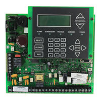
Addressable Fire Control Panel
Brand:
SILENT KNIGHT
| Category:
Smoke Alarm
| Size: 6 MB
Table of Contents
Installation Procedure
3
Table of Contents
5
Section 1
11
Introduction
11
Overview of Basic System
11
Hardware Features
11
Software Features
12
About this Manual
12
Terms Used in this Manual
12
Compatible Products
13
How to Contact Silent Knight
15
Section 2
19
Agency Listings, Approvals, and Requirements
19
Federal Communications Commission (FCC)
19
Underwriters Laboratories (UL)
21
Requirements for All Installations
21
Requirements for Central Station Fire Alarm Systems
22
Requirements for Local Protected Fire Alarm Systems
22
Requirements for Remote Station Protected Fire Alarm Systems - Digital Alarm Communicator Transmitter (DACT)
22
Section 3
23
Before You Begin Installing
23
What's in the Box
23
Environmental Specifications
23
Electrical Specifications
24
Wiring Specifications
25
Board Assembly Diagram
26
Calculating Current Draw and Standby Battery
27
Worksheet Requirements
27
Current Draw Worksheet for SK SLC Devices
28
Current Draw Worksheet for Hochiki SLC Devices
31
Maximum Battery Standby Load
33
Section 4
35
Control Panel Installation
35
Mounting the Control Panel Cabinet
35
Preventing Water Damage
35
Removing the 5700 Assembly from the Housing
35
Dead Front Installation and Removal
35
Dead Front Removal
36
Installing the Dead Front
36
AC Connection
37
Battery Connection
38
RBB Accessory Cabinet
39
Installing the RBB Accessory Cabinet and Batteries
39
SBUS Wiring
41
Calculating Wiring Distance for SBUS Modules
41
Wiring Configurations
44
How to Power SBUS Devices from Auxiliary Power Supply
44
Remote Annunciator 5860 Installation
45
Mounting the 5860
46
Flush Mounting
47
Surface Mounting
49
Model 5860 Connection to the Panel
50
5824 Serial/Parallel Printer Interface Module Installation
50
Selecting 5824 Options
52
5880 LED Driver Module
53
5880 Board Layout
53
FACP Connection
54
LED Wiring
55
Dry Contact Wiring
56
5865-3 / 5865-4 LED Annunciator Installation
57
FACP Connection
57
5865 Mounting
58
Configuring Modules
59
Assigning Module Ids
59
Telephone Connection
60
5211 Ground Start Relay
60
Notification Appliance/Auxiliary Power Circuits
61
Conventional Notification Appliance
61
Class B Notification Wiring
61
Class a Notification Wiring
62
Auxiliary Power Installation
63
Door Holder Power
63
Constant Power
64
Resettable Power
64
On-Board Relays (Conventional)
64
Common Trouble Relay
64
Programmable Relays
64
Remote Station Applications
65
Keltron Model 3158 Installation
65
City Box Connection Using the 5220 Module
66
NFPA 72 Polarity Reversal
67
Using the 5220 Module
67
Using the 7644 Module
69
Using the SD500-ARM Addressable Relay Module
70
Using a MR-201/T Control Relay from Air Products
71
Transmitter Activated by Dry Contacts
72
Section 5
73
SK and Hochiki SLC Device Installation
73
List of SK SLC Devices
73
List of Hochiki SLC Devices
74
Maximum Number of Devices
75
Wiring Requirements for SLC Devices
75
Wiring SLC in Style 4 (Class B) Configuration
75
Wiring SLC Devices in Style 6 & 7 (Class A) Configuration
78
Wiring SK SLC Detectors
79
Addressing SK SLC Devices
80
Wiring Hochiki Detectors
81
Addressing Hochiki Devices
82
Sd505-Aps, Sd505-Ahs, & Sd505-Ais
82
Hochiki SLC Devices with Dip Switches
84
Section 6
85
Programming Overview
85
Jumpstart Autoprogramming
85
Section 6 Programming Overview
85
Input Points
86
Output Points
86
Running Jumpstart
86
Mapping Overview
88
Input Point Mapping
89
Output Circuit Mapping
90
Zone Event Mapping
91
Mapping LED Points
93
Programming Using the 5660 Silent Knight Software Suite
94
Programming Using an Annunciator
94
Entering / Exiting the Program Menu
95
Moving through the Menus
95
Selecting Options and Entering Data
96
Editing Keys
96
Programming Menu Quick Reference
97
Section 7
103
Programming
103
UL 864 Programming Requirements
103
Section 7 Programming
103
SLC Family
104
Modules
104
Edit Modules
104
Module, Wiring Class
105
Naming Modules
105
Adding a Module
105
Deleting a Module
106
Zone
107
Edit Zone
107
Edit Zone Name
107
Edit Zone Properties
108
Alarm Delay Characteristics
109
Zone Outputs
110
Cadence Patterns
113
Add Zone
114
Delete Zone
114
View Zone Points
115
Group
116
Edit Group
116
Edit Group Name
116
Edit Group Properties
117
Silencing Options
118
Add Group
119
Delete Group
120
View Group Points
120
Edit Output Group Templates
121
Point
122
Point Programming for SLC
122
Point Programming for Internal or External Power Module (5496)
125
Point Programming for 5880 and 5865 Modules
126
Assigning a Name to a Points
127
System Options
128
Reporting Account
128
Edit Accounts
129
Events to Report
130
Switch Attempts
130
Telephone Number
130
Auto Test Time
131
Phone Lines
131
Dialing Prefix
132
Number of Answer Rings
132
Dial Option (Touchtone or Pulse)
133
Ground Start Relay
133
Line Monitor
133
Rotary Format
133
Answering Machine Bypass
134
Sys. Event Outputs
134
Trouble Events
135
System Alarm Cadence
136
Miscellaneous Options 1
137
Water Flow Delay
137
Automatic Daylight Savings Adjustment
138
Change AC Line Frequency
138
Clock Display Format (AM/PM or Military)
138
Low AC Report Delay
138
Miscellaneous Options 2
139
Auto Display Oldest Event
139
Report by Zone or by Point
139
Synchronize Strobes Active During Silence
139
Miscellaneous Options 3
140
Alarm Verification Time
140
Daylight Saving Time Start and End
140
Edit Banner Message
141
Jumpstart Autoprogramming
142
Computer Account
143
Access Codes
144
Profile Edit Menu
145
Edit Access Code
145
Edit Name
145
Panel Functions
145
Section 8
147
System Operation
147
Annunciator Description
147
LCD Displays
147
Section 8 System Operation
147
Banner
148
Menu System
148
Main Menu Overview
149
Using the Menus
149
Basic Operation
150
Setting Time and Date
150
Disable / Enable Nacs by Group
150
Disable / Enable a Template
150
Disable / Enable a Zone
150
Disable / Enable a Point
150
View Event History
151
To Clear the Event History
151
Conduct a Fire Drill
151
Conduct an Indicator Test
152
Conduct a Walk Test
152
Conduct a Dialer Test
153
Silence Alarms or Troubles
153
Reset Alarms
153
Check Detector through Point Status
153
View Status of a Point
154
View System Information
154
Reset Dialer
154
Communicating with a Remote Computer
155
Working with a Printer
156
Operation Mode Behavior
157
Releasing Operations
160
Single Interlock Zone Releasing
161
Double Interlock Zone Releasing
162
Smoke Alarm Verification
164
Section 9
165
Reporting
165
Receivers Compatible with the Control Panel
165
Reporting Formats Dialer Outputs
165
Section 9 Reporting
165
Section 10
173
Testing and Troubleshooting
173
Troubleshooting
173
Common Problems
173
Periodic Testing and Maintenance
174
Event History
175
Built-In Troubleshooting and Testing Tools
175
SLC Device Locator
175
SLC Multi Locator
176
I/O Point Control
177
Earth Ground Fault Resistance
177
Section 11
179
Installation Records
179
Detector and Module Point Record
179
Section 11 Installation Records
179
Appendix A Compatible Devices
181
Appendix B Special Characters Lists
195
Silent Knight Fire Product Warranty and Return Policy
197
Limited Warranty
199
Model 5700 Basic Operating Instructions
201
Advertisement
SILENT KNIGHT 5700 Installation And Operation Manual (184 pages)
Addressable Fire Alarm Control Panel
Brand:
SILENT KNIGHT
| Category:
Fire Alarms
| Size: 4 MB
Table of Contents
Installation Precautions
3
Table of Contents
5
Section 1
11
Introduction
11
Overview of Basic System
11
Hardware Features
11
Software Features
12
About this Manual
12
Terms Used in this Manual
12
Compatible Products
13
Section 2
15
Agency Listings, Approvals, and Requirements
15
Federal Communications Commission (FCC)
15
Underwriters Laboratories (UL)
16
Requirements for All Installations
16
Requirements for Central Station Fire Alarm Systems
17
Requirements for Local Protected Fire Alarm Systems
17
Requirements for Remote Station Protected Fire Alarm Systems
17
Section 3
18
Before You Begin Installing
18
What's in the Box
18
Environmental Specifications
18
Electrical Specifications
19
Wiring Specifications
20
Board Assembly Diagram
21
Calculating Current Draw and Standby Battery
22
Current Draw Worksheet Requirements
22
Current Draw Worksheet for SK SLC Devices
22
Current Draw Worksheet for SD SLC Devices
25
Maximum Battery Standby Load
27
Installation Tasks Overview
27
Section 4
30
Control Panel Installation
30
Mounting the Control Panel Cabinet
30
Preventing Water Damage
30
Removing the 5700 Assembly from the Housing
30
Dead Front Installation and Removal
30
Installing the Dead Front
31
Dead Front Removal
31
AC Connection
32
Battery Connection
33
RBB Accessory Cabinet
34
Installing the RBB Accessory Cabinet and Batteries
34
SBUS Wiring
36
Calculating Wiring Distance for SBUS Modules
36
Wiring Configurations
38
How to Power SBUS Devices from Auxiliary Power Supply
38
5860Emote Annunciator Installation
39
Mounting the 5860
40
Flush Mounting
42
Surface Mounting
43
Model 5860 Connection to the Panel
43
5824 Serial/Parallel Printer Interface Module Installation
44
Selecting 5824 Options
45
5880 LED Driver Module
46
5880 Board Layout
46
FACP Connection
47
LED Wiring
48
Dry Contact Wiring
48
5865-3 / 5865-4 LED Annunciator Installation
49
FACP Connection
50
5865 Mounting
50
Configuring Modules
51
Assigning Module Ids
51
Telephone Connection
52
Notification Appliance/Auxiliary Power Circuits
52
Conventional Notification Appliance
52
Class B Notification Wiring
53
Class a Notification Wiring
54
Auxiliary Power Installation
55
Door Holder Power
55
Constant Power
56
Resettable Power
56
Sounder Sync Power
56
On-Board Relays (Conventional)
56
Common Trouble Relay
56
Programmable Relays
56
Remote Station Applications
57
Keltron Model 3158 Installation
57
City Box Connection Using the 5220 Module
58
NFPA 72 Polarity Reversal
59
Using the 5220 Module
59
Using the 7644-L8 Module
60
Using the SD500-ARM Addressable Relay Module
60
Using a MR-201/T Control Relay from Air Products
62
Transmitter Activated by Dry Contacts
63
Section 5
64
SK and SD SLC Device Installation
64
List of SK SLC Devices
64
List of SD SLC Devices
65
Maximum Number of Devices
66
Wiring Requirements for SLC Devices
66
Wiring SLC in Style 4 (Class B) Configuration
66
Wiring SLC Devices in Style 6 & 7 (Class A)
68
Configuration
68
SK Detector Installation
69
Wiring SK Detectors
69
Addressing SK SLC Devices
70
SD Detector Installation
71
Wiring SD Detectors
71
Addressing SD SLC Devices
72
SD505-PHOTO or SD505-HEAT
72
SLC Devices with DIP Switches
73
Section 6
74
Programming Overview
74
Jumpstart Autoprogramming
74
Input Points
74
Output Points
74
Section 6 Programming Overview
74
Running Jumpstart
75
Mapping Overview
76
Input Point Mapping
77
Output Circuit Mapping
78
Zone Event Mapping
79
Mapping LED Points
81
Programming Using the 5660 Silent Knight Software Suite
82
Programming Using an Annunciator
82
Entering / Exiting the Program Menu
82
Moving through the Menus
83
Selecting Options and Entering Data
83
Editing Keys
84
Programming Menu Quick Reference
85
Section 7
99
Programming
99
UL 864 Programming Requirements
99
Section 7 Programming
99
Modules
100
Edit Modules
100
Naming Modules
100
Module, Wiring Class
100
Adding a Module
100
Deleting a Module
101
View Module List
101
Zone
101
Edit Zone
101
Edit Zone Name
102
Edit Zone Properties
102
Zone Outputs
104
Cadence Patterns
106
Zone Accessory Options
107
Add Zone
107
Delete Zone
107
View Zone Points
107
Group
108
Edit Group
108
Edit Group Name
108
Edit Group Properties
109
Add Group
111
Delete Group
111
View Group Points
111
Edit Output Group Templates
112
Point
113
Point Programming for SLC
113
Point Programming for Internal or External Power Module
115
Point Programming for 5880 and 5865 Modules
118
Assigning a Name to a Points
118
System Options
119
Reporting Account
119
Edit Accounts
119
Auto Test Time
122
Phone Lines
122
Dialing Prefix
123
Number of Answer Rings
123
Dial Option (Touchtone or Pulse)
123
Rotary Format
123
Line Monitor
123
Answering Machine Bypass
124
Sys. Event Outputs
124
Trouble Events
124
System Alarm Cadence
125
Time Options
125
Water Flow Delay
126
Alarm Verification Time
126
Low AC Report Delay
126
Clock Display Format (AM/PM or Military)
126
Change AC Line Frequency
127
Miscellaneous Options
127
Synchronize Strobes Active During Silence
127
Auto Display Oldest Event
127
Report by Zone or by Point
127
Single Key Acknowledge
128
Daylight Savings
128
Automatic Daylight Savings Adjustment
128
Daylight Saving Time Start and End
128
Edit Banner
128
SLC Family
129
Jumpstart Autoprogramming
130
Computer Account
130
Access Codes
131
Profile Edit Menu
132
Edit Name
132
Edit Access Code
132
Panel Functions
132
Section 8
133
System Operation
133
Default Codes
133
Annunciator Description
133
LCD Displays
133
Banner
133
Section 8 System Operation
133
Menu System
134
Main Menu Overview
134
Using the Menus
135
Basic Operation
135
Setting Time and Date
135
Disable / Enable Nacs by Group
135
Disable / Enable a Template
135
Disable / Enable a Zone
135
Disable / Enable a Point
135
View Event History
136
To Clear the Event History
136
Conduct a Fire Drill
136
Conduct an Indicator Test
136
Conduct a Walk Test
136
Conduct a Dialer Test
137
Silence Alarms or Troubles
137
Reset Alarms
137
Check Detector Sensitivity through Point Status
137
View Status of a Point
138
View Alarms, Supervisories or Troubles
138
View System Information
138
Reset Dialer
139
Communicating with a Remote Computer
139
Working with a Printer
140
Operation Mode Behavior
141
Releasing Operations
144
Single Interlock Zone Releasing
145
Double Interlock Zone Releasing
146
Smoke Alarm Verification
148
Section 9
149
Reporting
149
Receivers Compatible with the Control Panel
149
Reporting Formats Table
149
Section 9 Reporting
149
Section 10
158
Testing and Troubleshooting
158
Troubleshooting
158
Common Problems
158
Periodic Testing and Maintenance
159
Event History
159
Built-In Troubleshooting and Testing Tools
160
SLC Device Locator
160
SLC Multi Locator
160
I/O Point Control
161
Earth Fault Resistance
161
Section 11
162
Installation Records
162
Detector and Module Point Record
162
Section 11 Installation Records
162
Appendix A Compatible Devices
163
Appendix A Compatible Devices
164
Appendix B Special Characters Lists
177
Silent Knight Fire Product Warranty and Return Policy
180
Manufacturer Warranties and Limitation of Liability
180
SILENT KNIGHT 5700 Basic Operating Instructions (1 page)
Brand:
SILENT KNIGHT
| Category:
Control Panel
| Size: 0 MB
Advertisement
Advertisement
Related Products
SILENT KNIGHT 5207
SILENT KNIGHT 5084
Silent Knight 5104B
SILENT KNIGHT INTELLIKNIGHT 5820XL
SILENT KNIGHT INTELLIKNIGHT 5820XL-EVS
SILENT KNIGHT 5499
SILENT KNIGHT 5495
SILENT KNIGHT 5104
SILENT KNIGHT 5128
SILENT KNIGHT 5204
Silent Knight Categories
Fire Alarms
Control Panel
Security System
Cell Phone
Smoke Alarm
More Silent Knight Manuals
Login
Sign In
OR
Sign in with Facebook
Sign in with Google
Upload manual
Upload from disk
Upload from URL