SILENT KNIGHT INTELLIKNIGHT 5820XL Installation And Operation Manual
Fire alarm control/communicator, addressable fire system
Hide thumbs
Also See for INTELLIKNIGHT 5820XL:
- Installation and operation instruction manual (236 pages) ,
- Installation and operation manual (230 pages) ,
- Installation manual (198 pages)

Related Manuals for SILENT KNIGHT INTELLIKNIGHT 5820XL


Summary of Contents for SILENT KNIGHT INTELLIKNIGHT 5820XL
- Page 1 ® INTELLIKNIGHT 5820XL Addressable Fire System Installation and Document 151209-L8 Operations Manual 01/24/2013 Rev: P/N 151209-L8:U ECN 12-0955...
-
Page 3: Installation Procedure
Installation Procedure Installation Precautions - Adherence to the following will aid in problem-free installation with long-term reliability: WARNING - Several different sources of power can be connected to the fire alarm control panel. Disconnect all sources of power before servicing. Control unit and associated equipment may be damaged by removing and/or inserting cards, modules, or interconnecting cables while the unit is energized. - Page 4 These instructions must be followed to avoid damage to the control panel and associated equipment. FACP (Fire Alarm Control Panel) operation and reliability depend upon proper installation. While installing a fire alarm system may make lower insurance rates possible, it is not a substitute for fire insurance! An automatic fire alarm system - typically made up of smoke detectors, heat detectors, manual pull stations, audible warning devices, and a fire alarm control with remote notification capability - can provide early warning...
-
Page 5: Table Of Contents
Contents Section 1 Introduction .............................. 1-1 Overview of Basic System ......................1-1 1.1.1 Hardware Features ......................1-1 1.1.2 Software Features ......................1-2 About this Manual ........................1-2 1.2.1 Terms Used in this Manual ....................1-2 Compatible Products ........................1-3 How to Contact Silent Knight ....................1-4 Section 2 Agency Listings, Approvals, and Requirements ........ - Page 6 IntelliKnight 5820XL Installation Manual Section 4 Control Panel Installation ...................... 4-1 Mounting the Control Panel Cabinet ..................4-1 4.1.1 Preventing Water Damage ....................4-1 4.1.2 Removing the 5820XL Assembly from the Housing ............4-1 AC Connection .........................4-2 Battery Connection ........................4-3 4.3.1 RBB Accessory Cabinet .....................4-4 4.3.1.1 Installing the RBB Accessory Cabinet and Batteries ..........4-4...
- Page 7 Contents 4.13.1 Trouble Relay .........................4-41 4.13.2 Programmable Relays ....................4-41 4.14 Remote Station Applications ....................4-42 4.14.1 Keltron Model 3158 Installation ..................4-42 4.14.2 City Box Connection Using the 5220 Module ..............4-44 4.14.3 NFPA 72 Polarity Reversal .....................4-45 4.14.3.1 Using the 5220 Module ..................4-45 4.14.3.2 Using the 7644 Module ..................4-46 4.14.4 Using the SD500-ARM Addressable Relay Module ............4-48 4.14.5 Using a MR-201/T Control Relay From Air Products ............4-49...
- Page 8 IntelliKnight 5820XL Installation Manual Section 7 Programming ............................7-1 UL 864 Programming Requirements ..................7-1 SLC Family ..........................7-2 Modules ............................7-2 7.3.1 Edit Modules ........................7-2 7.3.1.1 Naming Modules ......................7-2 7.3.1.2 Setting the 5815XL Wiring Class ................7-3 7.3.2 Adding a Module ........................7-3 7.3.3 Deleting a Module ......................7-4 Zone ............................7-5...
- Page 9 Contents 7.7.4.3 Automatic Daylight Savings Adjustment ..............7-40 7.7.4.4 Clock Display Format (AM/PM or Military) .............7-40 7.7.4.5 Change AC Line Frequency ...................7-40 7.7.5 Miscellaneous Options 2 ....................7-41 7.7.5.1 Synchronize Strobes Active During Silence ............7-41 7.7.5.2 Auto Display Oldest Event ..................7-41 7.7.5.3 Report by Zone or by Point ..................7-41 7.7.6 Miscellaneous Options 3 ....................7-42 7.7.6.1 Alarm Verification Time ..................7-42 7.7.6.2 Plex Door Option ....................7-42...
- Page 10 IntelliKnight 5820XL Installation Manual Releasing Operations ......................8-17 8.7.1 Single Interlock Zone Releasing ..................8-18 8.7.2 Double Interlock Zone Releasing ..................8-19 Smoke Alarm Verification .......................8-21 Section 9 Reporting ..............................9-1 Receivers Compatible with the Control Panel ................9-1 Reporting Formats Dialer Outputs ..................9-1...
- Page 11 Notification Appliances ......................A-1 Two-Wire Smoke Detectors ....................A-12 Appendix B Special Characters Lists ......................B-1 Characters used for Naming ....................B-1 Silent Knight Fire Product Warranty and Return Policy Manufacturer Warranties and Limitation of Liability IntelliKnight 5820XL Basic Operating Instructions 151209...
- Page 12 IntelliKnight 5820XL Installation Manual 151209...
-
Page 13: Introduction
The IntelliKnight 5820XL Fire Alarm Control/Communicator is an addressable fire control system that meets the requirements of UL 864. Overview of Basic System The IntelliKnight 5820XL base system is packaged as an assembled stack of 3 circuit boards mounted to an aluminum housing. 1.1.1 Hardware Features •... -
Page 14: Software Features
5820XL. Please let us know if the manual does not meet your needs in any way. We value your feedback! 1.2.1 Terms Used in this Manual The following terminology is used with the IntelliKnight 5820XL system: Table 1-1 Manual Terminology Term Description... -
Page 15: Compatible Products
Introduction Compatible Products Table 1-2 lists the products available from Silent Knight for use with the IntelliKnight 5820XL. Table 1-2: 5820XL Compatible Products Type of Model Description Device See Section 5.1 for a list of compatible devices. Addressable Devices See Section 5.2 for a list of compatible devices. Addressable Devices Other... -
Page 16: How To Contact Silent Knight
IntelliKnight 5820XL Installation Manual The following modems have been tested by Silent Knight for compatibility with the 5820XL and the Silent Knight Software Suite software packages: Table 1-3: Compatible Modems Manufacturer Model US Robotics 28.8 LifeStyle Motorola 28.8, 3400 series Premier 33.6... - Page 17 Introduction Limitations of Fire Alarm Systems Manufacturer recommends that smoke and/or heat detectors be located throughout a protected premise following the recommendations of the current edition of the National Fire Protection Association Standard 72 (NFPA 72), manufacturer’s recommendations, State and local codes, and the recommendations contained in Guide for the Proper Use of System Smoke Detectors, which is made available at no charge to all installing dealers.
- Page 18 IntelliKnight 5820XL Installation Manual materials, etc.). • Heat detectors do not sense particles of combustion and are designed to alarm only when heat on their sensors increases at a predetermined rate or reaches a predetermined level. Heat detectors are designed to protect property, not life.
- Page 19 Introduction Requirements and recommendations for proper use of fire alarm systems in- cluding smoke detectors and other fire alarm devices: Early fire detection is best achieved by the installation and maintenance of fire detection equipment in all rooms and areas of the house or building in accordance with the requirements and recommendations of the current edition of the National Fire Protection Association Standard 72, National Fire Alarm Code (NFPA 72), the manufacturer’s recommendations, State and local codes and the recommendations...
- Page 20 IntelliKnight 5820XL Installation Manual 151209...
-
Page 21: Agency Listings, Approvals, And Requirements
Section 2 Agency Listings, Approvals, and Requirements Federal Communications Commission (FCC) 1. The following information must be provided to the telephone company before the IntelliKnight 5820XL can be connected to the phone lines: Manufacturer: Silent Knight by Honeywell Model Number:... - Page 22 IntelliKnight 5820XL Installation Manual disconnect the 5820XL until the problem has been resolved. This product cannot be adjusted or repaired in the field. It must be returned to the factory for service. This equipment is not designed for use with party line service. Connection to party line service is subject to state tariffs.
-
Page 23: Underwriters Laboratories (Ul)
Agency Listings, Approvals, and Requirements Underwriters Laboratories (UL) 2.2.1 Requirements for All Installations General requirements are described in this section. When installing an individual device, refer to the specific section of the manual for additional requirements. The following subsections list specific requirements for each type of installation (for example, Central Station Fire Alarm systems, Local Protected Fire Alarm systems, and so on). -
Page 24: Requirements For Central Station Fire Alarm Systems
IntelliKnight 5820XL Installation Manual 2.2.2 Requirements for Central Station Fire Alarm Systems 1. Use both phone lines. Enable phone line monitors for both lines. 2. You must program a phone number and a test time so that the 5820XL sends an automatic daily test to the central station. -
Page 25: Before You Begin Installation
This section of the manual is intended to help you plan your tasks to facilitate a smooth installation. Please read this section thoroughly, especially if you are installing a 5820XL panel for the first time. What’s in the Box? The IntelliKnight 5820XL ships with the following hardware: • A cabinet with all hardware assembled •... -
Page 26: Electrical Specification
IntelliKnight 5820XL Installation Manual Electrical Specification Table 3-1 list the terminal block on the 5820XL as well as a description of each individual terminal and their respective electrical rating. Table 3-1: Terminal Descriptions and Electrical Specifications Rating Earth Ground Terminal # and Label... - Page 27 Before You Begin Installation Table 3-1: Terminal Descriptions and Electrical Specifications Rating Earth Ground Terminal # and Label Description Faults Voltage Current N.C. RELAY 1 General Purpose Relay 1 24 VDC 2.5 A, resistive N.O. N.C. TROUBLE Trouble Relay 24 VDC 2.5 A, resistive N.O.
-
Page 28: Wiring Specifications
IntelliKnight 5820XL Installation Manual Wiring Specifications Induced noise (transfer of electrical energy from one wire to another) can interfere with telephone communication or cause false alarms. To avoid induced noise, follow these guidelines: • Isolate input wiring from high current output and power wiring. Do not pull one multi-conductor cable for the entire panel. - Page 29 Before You Begin Installation AC Input Route all low voltage wiring through any of these knockouts. To phone lines Battery cables from Maintain 1/4" under aluminum housing. spacing between battery cables All circuits, except battery and input wiring. cables and AC, are power limited. Maintain at least 1/4"...
-
Page 30: Board Assembly Diagram
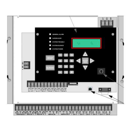
IntelliKnight 5820XL Installation Manual Board Assembly Diagram On-board Annunciator To AC Chassis Mounting Chassis Nuts Mounting Nuts Key Switch Input Programming Ports Figure 3-2 Model 5820XL Assembly Figure 3-2 shows the circuit boards, metal housing and annunciator that attach the 5820XL assembly to the cabinet. -
Page 31: Calculating Current Draw And Standby Battery
Before You Begin Installation Calculating Current Draw and Standby Battery This section is for helping you determine the current draw and standby battery needs if you are using SK addressable devices (Table 3-2) or SD addressable devices (Table 3-3). 3.6.1 Current Draw Worksheet Requirements The following steps must be taken when determining 5820XL current draw and standby battery requirements. -
Page 32: Current Draw Worksheet For Sk Slc Devices
IntelliKnight 5820XL Installation Manual 3.6.1.1 Current Draw Worksheet for SK SLC Devices Use Table 3-2 to determine current requirements during alarm/battery standby operation when SK SLC devices are installed. You can install up 99 SK detectors per loop (396 max per panel) and 99 SK modules per loop (396 max per panel). Copy this section if additional space is required. - Page 33 Before You Begin Installation Standby Alarm Device # of Devices Current per Device Current Current Addressable SLC Modules SK-Monitor SK-Minimon Standby/Alarm: .375 mA SK-Pull-SA SK-Pull-DA SK-Monitor-2 Standby/Alarm: .75 mA SK-Mon-10 Standby/Alarm: 3.5 mA Standby: 2.25 mA Alarm: 2.25 mA SK-Control Standby: 1.7 mA Aux Pwr...
- Page 34 IntelliKnight 5820XL Installation Manual Standby Alarm Device # of Devices Current per Device Current Current 5865-4 LED Annunciator Standby: 35 mA (with reset and silence Alarm: 145 mA switches) Standby: 35 mA (8 max.) 5865-3 LED Annunciator Alarm: 145 mA...
-
Page 35: Current Draw Worksheet For Sd Slc Devices
Current For each device use this formula: This column This column Current per number of devices. Standby: 215 mA 215 mA IntelliKnight 5820XL Fire Panel (Current draw from battery) Alarm: 385 mA 385 mA Addressable SLC Devices SD500-AIM SD500-MIM SD500-PS... - Page 36 IntelliKnight 5820XL Installation Manual Standby Alarm Device # of Devices Current per Device Current Current 5865-4 LED Annunciator Standby: 35 mA (with reset and silence switches) Alarm: 145 mA Standby: 35 mA 5865-3 LED Annunciator (8 max.) Alarm: 145 mA...
-
Page 37: Maximum Battery Standby Load
Before You Begin Installation 3.6.1.3 Maximum Battery Standby Load Table 3-4 shows the maximum battery standby load for the 5820XL based on 24 and 60 hours of standby. The standby load calculations of line D in the Current Draw Calculation Worksheet (Table 3-2 for SK devices and Table 3-3 for SD devices) must be less than the number shown in Table 3-4 for the battery size used and standby hours required. -
Page 38: Installation Tasks Overview
This section provides a chart listing tasks that need to be performed when installing the IntelliKnight 5820XL system. The chart is intended to be a handy way for you to make sure you have completed all necessary tasks. Unless noted, these tasks do not have to be performed in the order they are listed here. - Page 39 Before You Begin Installation See Sec. Task (for more info.) Set up reporting accounts. 7.7.1 Select options for phone lines. 7.7.2 Select system-wide response to trouble conditions, if desired. 7.7.3 Select system-wide cadence patterns for special conditions (fire drill, Aux1 7.7.3 and Aux2 alarms) if desired.
- Page 40 IntelliKnight 5820XL Installation Manual See Sec. Task (for more info.) Disable (set to UNUSED) any unused circuits. If you do not disable unused output circuits, they will cause a trouble condition (unless an EOL resistor is used). Select a name for the point.
-
Page 41: Control Panel Installation
Section 4 Control Panel Installation Caution! To avoid the risk of electrical shock and damage to the unit, power should be OFF at the control panel while installing or servicing. Mounting the Control Panel Cabinet Read the environmental specifications in Section 3.2 before mounting the control panel cabinet. -
Page 42: Ac Connection
IntelliKnight 5820XL Installation Manual AC Connection At installation, connect the AC terminals to the power source as shown in Figure 4-1. It may be necessary for a professional electrician to make this connection. The AC terminals are rated at 120 VAC, 50 or 60 Hz, 2.5A. -
Page 43: Battery Connection
Control Panel Installation Battery Connection The control panel battery charge capacity is 7.0 to 35 AH. Use 12V batteries of the same AH rating. Determine the correct AH rating as per your current load calculation (see Section 3.6). Wire batteries in series to produce a 24-volt equivalent. Do not parallel batteries to increase the AH rating. -
Page 44: Rbb Accessory Cabinet
IntelliKnight 5820XL Installation Manual 4.3.1 RBB Accessory Cabinet The Model RBB Accessory cabinet can be used when you are required to use backup batteries that are too large to fit into the main control panel cabinet. The RBB cabinet holds batteries up to the 35 AH size. The RBB dimensions are 16"... - Page 45 Control Panel Installation 3. Run extended battery cable from control panel cabinet through conduit to RBB cabinet. See Figure 4-5. RBB Cabinet Cover Screws Conduit Coupler Conduit RBB Cabinet Cover Screws Figure 4-5 Battery Connections in the RBB Cabinet Note: Figure 4-5 is an example of how the wire connections can be routed. However, any other cabinet knock-outs (on either the main control panel or the RBB cabinet), that are not previously being used may be utilized to connect conduit between the two cabinets.
-
Page 46: Sbus Wiring
IntelliKnight 5820XL Installation Manual SBUS Wiring This section contains information on calculating SBUS wire distances and the types of wiring configurations (Class A and B). 4.4.1 Calculating Wiring Distance for SBUS Modules The following instructions will guide you in determining the type of wire and the maximum wiring distance that can be used with control panel SBUS accessory modules. - Page 47 Control Panel Installation These cases are marked in the chart with an asterisk (*). Maximum length can never be more than 6,000 feet, regardless of gauge used. The formula used to generate this chart is shown in the note below. Table 4-1: Wire Distances Per Wire Gauge Using Copper Wire Wiring Distance: SBUS Modules to Panel Total Worst Case...
- Page 48 IntelliKnight 5820XL Installation Manual Wiring Distance calculation example: Suppose a system is configured with the following SBUS modules: 2 - Module 5860 Fire Annunciator 1 - 5895XL Intelligent Power Expander 1 - 5865 LED Annunciator 1 - 5824 Serial/Parallel Interface Module...
-
Page 49: Wiring Configurations
Control Panel Installation 4.4.2 Wiring Configurations Figure 4-7 illustrates Class A wiring configuration and Figure 4-8 illustrates Class B configuration. Supervised Power Limited Caution For proper system supervision do not use looped wire under terminals marked A, B, +, and - of the SBUS device connectors. -
Page 50: Remote Annunciator 5860 Installation
IntelliKnight 5820XL Installation Manual Remote Annunciator 5860 Installation The optional Model 5860 Remote Annunciator, shown in Figure 4-9, performs the same functions as the on-board annunciator. Up to 8 annunciators can be added to the IntelliKnight 5820XL system. Figure 4-9 Model 5860 Remote Annunciator, Front View 5860 installation involves the following steps: 1. -
Page 51: Mounting The 5860
Control Panel Installation 4.5.1 Mounting the 5860 This section of the manual describes mounting the remote annunciator. The annunciator can be flush- or surface-mounted. Figure 4-10 shows the parts of the annunciator. Instructions for disassembling and mounting appear on the following pages. Figure 4-10 Annunciator Parts 151209 4-11... -
Page 52: Flush Mounting
IntelliKnight 5820XL Installation Manual The 5860 comes from the factory fully assembled. You must disassemble it for mounting. To disassemble the annunciator, use a 5/64 hex wrench to remove the set screws, located on the bottom of the annunciator bezel. (See Figure 4-11 for location of the set screws.) - Page 53 Control Panel Installation Flush Mounting with an Electrical Box The 5860 annunciator can be used with the following types of electrical boxes: 4S, single-gang, and double-gang. If an electrical box is used, the box must be 1-3/8” back from the face of the wall to accommodate the annunciator.
-
Page 54: Surface Mounting
IntelliKnight 5820XL Installation Manual 4. After the annunciator wiring to the panel has been completed (described in Sec- tion 4.5.2), replace the electronic assembly in the back box. Place the bezel over the back box and tighten the set screws on the bezel. -
Page 55: Model 5860 Connection To The Panel
Control Panel Installation 4.5.2 Model 5860 Connection to the Panel Connect the 5860 to the panel as shown in Figure 4-14. Supervised Power Limited Figure 4-14 Model 5860 Connection to the Panel 151209 4-15... -
Page 56: 5815Xl Installation
IntelliKnight 5820XL Installation Manual 5815XL Installation The 5815XL SLC expander lets you add 127 SD addressable devices or 99 SK detectors and 99 SK modules. Add up to three 5815XLs to a system to achieve the maximum number of devices on the system. -
Page 57: 5815Xl Connection To The Panel
Control Panel Installation 4.6.1 5815XL Connection to the Panel Connect the 5815XL to the control panel as shown in Figure 4-16. After the 5815XL is connected to the panel, it must be added to the system. This programming step is described in Section 4.10. -
Page 58: 5824 Serial/Parallel Interface Module Installation
IntelliKnight 5820XL Installation Manual 5824 Serial/Parallel Interface Module Installation The 5824 serial/parallel interface module allows you to connect a printer to the panel, so you can print a real-time log of system events, a report of detector status, and event history. Instructions for installing the 5824 appear below. The 5824 is for ancillary use only. -
Page 59: Selecting 5824 Options
Control Panel Installation Model 5824 (with housing) To Serial Printer To Parallel Printer Figure 4-18 Printer Connection 4.7.1 Selecting 5824 Options Configuring the 5824 includes the following steps: • Add the module to the system. JumpStart will add the module automatically (see Section 6.1). - Page 60 IntelliKnight 5820XL Installation Manual Printer and Output Port Options 1. From the Installer Main Menu, select for Program Menu. 2. Select for Module. 3. Select for Edit Module. 4. From the list that displays, select the 5824 module you want to configure.
-
Page 61: 5880 Led I/O Module
Control Panel Installation 5880 LED I/O Module The 5880 is an LED driver board that can be used in a wide variety of applications, including as an interface with most customized floor plan annunciator boards. The 5880 can drive up to 40 LEDs and has one PZT controller. The 5880 also has eight inputs for monitoring. -
Page 62: 5880 Connection To Panel
IntelliKnight 5820XL Installation Manual 4.8.2 5880 Connection to Panel The 5880 connects to the panel via the SBUS. Make connections as shown in Figure 4-21. After the 5880 is connected to the panel, it must be added to the system. This programming step is described in Section 4.10. -
Page 63: Led Wiring
Control Panel Installation 4.8.3 LED Wiring There are four 12-pin connectors on the 5880 board for connecting LEDs. Each LED gets its power from Pin 11. Internal resistors are sized so that there is approximately 10 mA of current for each LED, no series resistors are required. LED outputs can be mapped to output circuits. -
Page 64: Dry Contact Wiring
IntelliKnight 5820XL Installation Manual 4.8.4 Dry Contact Wiring The 8 input circuits on the 5880 board are for monitoring switch inputs-any type of switch supported by the control panel can be used with the 5880. For example, you can use a 5880 to monitor pull stations, water flow, tamper, reset, or silence switches. -
Page 65: 5865-3 / 5865-4 Led Annunciator Installation
Control Panel Installation 5865-3 / 5865-4 LED Annunciator Installation The 5865-3 and 5865-4 are LED annunciators. The 5865-4 has 30 mappable LEDs, remote silence and reset key switches, and a general system trouble LED. The 5865- 3 has 30 mappable LEDs only. These are arranged as 15 pairs of red (typically used for alarm) and yellow (typically used for trouble) LEDs. -
Page 66: Facp Connection
IntelliKnight 5820XL Installation Manual 4.9.1 FACP Connection The 5865 connects to the panel via the SBUS. Make connections as shown in Figure 4-25. After the 5865 is connected to the panel, it must be added to the system. This programming step is described in Section 4.10. -
Page 67: 5865 Mounting
Control Panel Installation 4.9.2 5865 Mounting Mount the 5865-4 to a standard 4-gang electrical box. Mount the 5865-3 to a standard 3-gang electrical box. In Figure 4-26, the 5865-4 attached to a 4-gang box is used as an example. Figure 4-26 5865 Mounting Example The 5865 ships with a set of zone description labels that can be inserted into the 5865 board assembly. - Page 68 IntelliKnight 5820XL Installation Manual show through the label when illuminated. Figure 4-27 Inserting Zone Description Labels 4-28 151209...
-
Page 69: Configuring Modules
Control Panel Installation 4.10 onfiguring Modules This section describes how to configure any system hardware modules that have been added to the system. 4.10.1 Assigning Module IDs When installing a hardware module (such as, 5815XL, 5824, 5860, 5895XL, 5865-3 or 5865-4), you must use the DIP switches on the module to assign an ID# to the module. -
Page 70: Telephone Connection
IntelliKnight 5820XL Installation Manual 4.11 Telephone Connection Connect the telephone lines as shown in Figure 4-29. The Model 7860 phone cord is available from Silent Knight for this purpose. A number of programmable options are available for customizing telephone lines. -
Page 71: Flexputs ™ I/O Circuits
Control Panel Installation ™ 4.12 Flexputs I/O Circuits The six Flexput™ circuits are an innovative and versatile feature of the control panel. They can be used as: Class A or B notification circuits, Class A or B initiation circuits (either 2 or 4 wire detectors), or as auxiliary power (resettable, continuous, or door holder). - Page 72 IntelliKnight 5820XL Installation Manual 2. Configure the circuit through programming (see Section 7.6). Alarm Polarity Notification Wiring UL Listed EOL Supervised Model 7628 Power Limited 4.7 k Max. Impedance: 1.5 Regulated 24 VDC Full Wave Rectified 27.4 VDC, 3A per Circuit, 6A max Combined...
-
Page 73: Class A Notification Wiring
Control Panel Installation 4.12.1.2 Class A Notification Wiring You must use an appliance from the list of compatible appliances in the Appendix at the back of this manual. To install a Class A notification appliance circuit: 1. Wire the Class A notification appliances as shown in Figure 4-31. Caution For proper system supervision do not use looped wire under terminals marked O and X of the Flexput connectors. -
Page 74: Conventional Input Switch Circuits
IntelliKnight 5820XL Installation Manual 4.12.2 Conventional Input Switch Circuits This section of the manual explains how to install conventional initiating devices for Class A (Style D) or Class B (Style B) configurations. 4.12.2.1 Class B Inputs You can connect conventional Class B switches, such as waterflow switches and pull stations, directly to the Flexput circuits of the control panel. -
Page 75: Class A Inputs
Control Panel Installation 4.12.2.2 Class A Inputs You can connect conventional Class A switches, such as waterflow switches and pull stations, directly to the Flexput circuits of the control panel. To install a Class A switch: 1. Wire the Class A switch as shown in Figure 4-33. 2. -
Page 76: Installing 2-Wire Smoke Detectors
IntelliKnight 5820XL Installation Manual 4.12.3 Installing 2-Wire Smoke Detectors Any compatible U.L. listed two-wire smoke detector can be used with the control panel (see Appendix A for list of compatible smoke detectors). Figure 4-34 and Figure 4-35 illustrate how to connect a UL listed 2-wire detector to the control panel. -
Page 77: Installing 2-Wire Class A Smoke Detectors
Control Panel Installation 4.12.3.2 Installing 2-Wire Class A Smoke Detectors To install a Class A two-wire smoke detector, wire as shown in Figure 4-35. Supervised Power Limited Note: Flexput circuit 5 and 6 used as an example. Any Flexput point pairing could be used. -
Page 78: Installing 4-Wire Smoke Detectors
IntelliKnight 5820XL Installation Manual 4.12.4 Installing 4-Wire Smoke Detectors Any compatible U.L. listed four-wire smoke detector can be used with the control panel (see Appendix A for list of compatible smoke detectors). Figure 4-34 and Figure 4-35 illustrate how to connect a UL listed four-wire detector to the control panel. -
Page 79: Installing 4-Wire Class A Smoke Detectors
Control Panel Installation 4.12.4.2 Installing 4-Wire Class A Smoke Detectors Figure 4-37 illustrates how to install 4-wire Class A detectors. Conventions used for wiring 4-wire Class A loops: 1. Up to two Class A 4-wire loops can be connected to the control panel at once. 2. -
Page 80: Auxiliary Power Installation
IntelliKnight 5820XL Installation Manual 4.12.5 Auxiliary Power Installation Flexput Circuits 1-6 on the control panel can be used as auxiliary power circuits. The three types of auxiliary power available are: • Door Holder Power (see Section 4.12.5.1) • Constant Power (see Section 4.12.5.2) •... -
Page 81: Resettable Power
Control Panel Installation 4.12.5.3 Resettable Power Resettable power is typically used to power beam detectors, flame detectors and conventional 4-wire smoke detectors. For circuits selected as Resettable, 24-volt power is always present at the terminals unless a system reset occurs. If a system reset occurs, power is disconnected from the terminals for 30 seconds, then re- applied. -
Page 82: Remote Station Applications
IntelliKnight 5820XL Installation Manual 4.14 Remote Station Applications 4.14.1 Keltron Model 3158 Installation The control panel is compatible with Keltron Model 3158, used for direct connection to a Keltron receiver. The 3158 reports alarms, supervisories, and troubles. The steps for connecting the 3158 to the control panel. Refer to the 3158 installation instructions for complete information. - Page 83 Control Panel Installation Not suitable for remote station protected premise service where separate transmission circuits are required for fire supervisory (if applicable), and Example trouble signals. Intended for connection to a polarity reversal circuit of a remote station receiving unit having compatible ratings.
-
Page 84: City Box Connection Using The 5220 Module
IntelliKnight 5820XL Installation Manual 4.14.2 City Box Connection Using the 5220 Module This section describes how to connect the control panel to a local energy municipal fire alarm box or “city box” as required by NFPA 72 Auxiliary Protected Fire Alarm systems for fire alarm service. -
Page 85: Nfpa 72 Polarity Reversal
Control Panel Installation the control panel. Note: Flexput Circuit 1 used as an example. Any Flexput circuit could be used. All circuits non-power-limited. All wiring non-supervised. Figure 4-41 City Box Connection 4.14.3 NFPA 72 Polarity Reversal Note: Intended for connection to a polarity reversal circuit of a control unit at the protected premises having compatible rating. -
Page 86: Using The 7644 Module
IntelliKnight 5820XL Installation Manual 4. Program the Flexput circuit used as a notification circuit, continuous and non- silencing. Refer to Section 7.4.1 for zone grouping and mapping. 5. If necessary, adjust loop current using the potentiometer (R10) on the 5220 board . - Page 87 Control Panel Installation 4. Program the output group characteristics as non-silenceable and reverse polarity. See Section 7.5.1.2. Figure 4-43 Polarity Reversal Connection Using the 7644 151209 4-47...
-
Page 88: Using The Sd500-Arm Addressable Relay Module
IntelliKnight 5820XL Installation Manual 4.14.4 Using the SD500-ARM Addressable Relay Module When the SD500-ARM is wired for polarity reversal, it reports alarm and trouble events to a remote site. Alarms will override trouble conditions and it will not be possible to reset the remote indicator until the condition is cleared and the control panel is reset. -
Page 89: Using A Mr-201/T Control Relay From Air Products
Control Panel Installation 4.14.5 Using a MR-201/T Control Relay From Air Products When the MR-201/T control relay is wired for polarity reversal, it reports alarm and trouble events to a remote site. Alarms will override trouble conditions and it will not be possible to reset the remote indicator until the condition is cleared and the control panel is reset. -
Page 90: Transmitter Activated By Dry Contacts
IntelliKnight 5820XL Installation Manual 4.14.6 Transmitter Activated by Dry Contacts This section describes the connection of a UL 864 listed remote station transmitter to the 5820XL FACP dry contacts. The FACP contacts must be supervised by the remote station transmitter module using end-of-line resistors (ELRs) with a value determined by the transmitter manufacturer. -
Page 91: Sd And Sk Slc Device Installation
Section 5 SD and SK SLC Device Installation Caution! To avoid the risk of electrical shock and damage to the unit, power should be OFF at the control panel while installing or servicing. List of SK SLC Devices The following SK SLC devices can be used with the control panel. See the appropriate section number in this manual or the device installation instructions (packaged with the device) for more information. -
Page 92: List Of Sd Slc Devices
IntelliKnight 5820XL Installation Manual Installation Model Name/Description Part Number Instruction PN B200S Sounder Base I56-3387-00 B201LP 6" mounting base I56-0595-00 B224BI 6" isolator base I56-0725-00 B224RB 6" relay base I56-3737-00 B200SR Sounder base I56-3392-00 B501 4" mounting base I56-0357-00 List of SD SLC Devices The following SD SLC devices can be used with the control panel. -
Page 93: Maximum Number Of Devices
SD and SK SLC Device Installation Maximum Number of Devices The 5820XL supports SK or SD devices on one 5820XL system. The maximum number of devices per system varies depending on device protocol and the number of 5815XL signaling circuit loop (SLC) expanders added to the system. Device support is as follows: •... -
Page 94: Wiring Requirements For Slc Devices
IntelliKnight 5820XL Installation Manual Wiring Requirements for SLC Devices The following information applies to all SLC devices. Refer to the section that describes the type of device you are installing for details. 5.4.1 Wiring 5815XL in Style 4 (Class B) Configuration No special wire is required for addressable loops. - Page 95 SD and SK SLC Device Installation Figure 5-1 and Figure 5-2 show how wire length is determined for out-and-back tap and T-tap style wiring. Figure 5-1 Calculating wire run length for a simple out and back tap When using T-taps, the total length of all taps and the main bus must not exceed 40,000 feet.
-
Page 96: Wiring 5815Xl In Style 6 & 7 (Class A) Configuration
IntelliKnight 5820XL Installation Manual 5.4.2 Wiring 5815XL in Style 6 & 7 (Class A) Configuration Figure 5-3 illustrates how to wire the SLC loop for Style 6 or Style 7 Class A installations. Note: Style 6 does not use short circuit isolator devices. -
Page 97: Wiring Sk Slc Detectors
SD and SK SLC Device Installation Wiring SK SLC Detectors This section describes how to install SK heat and smoke detectors. All detectors ship with installation instructions. Refer to the detector’s installation instructions for more detailed information. This information applies to the following SK models: •... -
Page 98: Addressing Sk Slc Devices
IntelliKnight 5820XL Installation Manual Addressing SK SLC Devices All SK devices are addressed using the two rotary dials that appear on the device board. Use the ONES rotary dial to set the ones place in a one or two digit number, and use the TENS rotary dial to set the tens place in a two digit number. -
Page 99: Wiring Sd Detectors
SD and SK SLC Device Installation Wiring SD Detectors The information in this section applies to the following SD models: This section describes how to install SD heat and smoke detectors. All detectors ship with installation instructions. Refer to each detectors' installation instructions for more detailed information. -
Page 100: Addressing Sd Devices
IntelliKnight 5820XL Installation Manual Addressing SD Devices This section explains how to address SD detectors and modules. 5.8.1 SD505-APS, SD505-AHS, & SD505-AIS The SD505-APS photoelectric smoke detector, SD505-AHS heat detector, and SD505-AIS ionization smoke detector are easily addressed at the FACP. The Installer Code is required to perform this task. -
Page 101: Slc Devices With Dip Switches
SD and SK SLC Device Installation 5.8.2 SLC Devices with DIP Switches Input and relay module addresses are set using the DIP switches on the module board. The chart below shows the available addresses. For example, to select address 3, place DIP switches 1 and 2 in the up position. The range of valid addresses is 1-127. - Page 102 IntelliKnight 5820XL Installation Manual 5-12 151209...
-
Page 103: Programming Overview
Section 6 Programming Overview This section of the manual is intended to give you an overview of the programming process. Please read this section of the manual carefully, especially if you are programming the control panel for the first time. The JumpStart AutoProgramming feature automates many programming tasks and selects default options for the system. -
Page 104: Input Points
IntelliKnight 5820XL Installation Manual 6.1.1 Input Points JumpStart will determine the number and type of input points (detectors or contact monitor modules) on each SLC loop. JumpStart assigns the correct detector type (heat, ionization or photoelectric), so the installer does not need to edit the device type for detectors. -
Page 105: Running Jumpstart
Programming Overview 6.1.3 Running JumpStart Run JumpStart immediately after you have addressed and connected all input devices (detectors, pull stations, and so on) and output devices (notification appliances, relays, and so on). Note: If you need to install a few devices after you have run JumpStart, you can install them manually. Follow instructions in Section 8 for configuration. - Page 106 IntelliKnight 5820XL Installation Manual 1. If you are ready to make the JumpStart configuration permanent, - Accept Configuration select 2. The system will ask you if the installation contains any addressable duct detectors. If there are none, select for No and skip to Step 8.
-
Page 107: Mapping Overview
Programming Overview Mapping Overview This section of the manual is an overview of mapping. Details about how to select mapping options appear in the appropriate subsections in Section 7. Mapping is an important concept with the control panel. In general terms, mapping is assigning or linking events to outputs that should activate when events occur. -
Page 108: Input Point Mapping
IntelliKnight 5820XL Installation Manual 6.2.1 Input Point Mapping Input points are assigned to input zones, as the example in Figure 6-2 shows. Any input point can be assigned to any input zone. (Input points can be assigned to one zone only. An input point can be designated as “Unused,” which means it has not been assigned to a zone.) -
Page 109: Output Circuit Mapping
Programming Overview 6.2.2 Output Circuit Mapping Figure 6-3 is a simple example showing how to assign notification and relay output circuits to groups. For an example of a simple floor above/floor below application, see Figure 6-5. Figure 6-3 Assigning Output Circuits to Groups (Example) 151209... -
Page 110: Zone Event Mapping
IntelliKnight 5820XL Installation Manual 6.2.3 Zone Event Mapping There are 11 types of events that can occur in zones (see below). For each event type, you can activate up to 8 output groups and patterns. If it is necessary to map to more than 8 output groups, an output group template may be used (see Section 7.5.5... - Page 111 Programming Overview Figure 6-5 Example of Zone Events Mapped to Output Groups and Patterns 151209...
-
Page 112: Mapping Led Points
IntelliKnight 5820XL Installation Manual 6.2.4 Mapping LED Points Figure 6-6 is a simple example showing how LED points are mapped to zones and output groups. Typically you would create two output groups for each zone, one for alarms and one for troubles. (LED points are available when Models 5865-3/4 and/or 5880 are used with the system). -
Page 113: Programming Using The 5660 Silent Knight Software Suite
Programming Overview Programming Using the 5660 Silent Knight Software Suite You can use the 5660 Silent Knight Software Suite (SKSS) to program the control panel onsite or remotely. SKSS is an optional software package that lets you easily program the control panel using a Windows-based computer and a modem* When using SKSS, you can set up the programming options for the panel, save the options in a file, then download the file to the panel. -
Page 114: Moving Through The Menus
IntelliKnight 5820XL Installation Manual To exit Program Mode: When you have completed working with the menus, press (left arrow) several times until you are exited from programming mode. Two prompts will display. The first prompt is to make sure you intended to leave the Program Menu (select Yes or No as appropriate). -
Page 115: Editing Keys
Programming Overview 6.4.1.3 Editing Keys The keys shown in Figure 6-9 are available for use when you are in the Programming menu. Use to scroll through the available options within a field. Up/down arrows Use to scroll through the fields on the screen. (left arrow) backs out of a screen and Left/right arrows returns you to the previous menu. -
Page 116: Programming Menu Quick Reference
IntelliKnight 5820XL Installation Manual Programming Menu Quick Reference This section of the manual lists all Program Menu options in the order they appear on the sub-menus. Default settings are indicated in text or marked with an asterisk. The comments column provide quick information and a reference to a section (if applicable) which has more detailed information. - Page 117 Programming Overview Menu Options/Defaults Comments Enter Name1 Enter Number1 Edit Zone Name Section 7.4.1.1 Enter Name2 Enter Number2 *1 Count 2 Count Alarm Ver. Verification Type Section 7.4.1.2 Zone Properties SNGL ILOCK DBL ILOCK 135° to Heat Temp Set Section 7.4.1.2 150°F Select Zone to Manual Pull...
- Page 118 IntelliKnight 5820XL Installation Manual Menu Options/Defaults Comments Enter Name1 Enter Number1 Group Name Section 7.5.1.1 Enter Name2 Enter Number2 Latching *Non- Options Latching Section 7.5.1.2 Latching *SILENCE Silenceable Section 7.5.1.2 NON-SIL Non-Silenceable Section 7.5.1.2 Auto Auto Un- Unsilence silenced Section Silencing 7.5.1.2...
- Page 119 Programming Overview Menu Options/Defaults Comments PHOTO PHOTO DUCT PHOTO HEAT SK DETECTORS ACCLIMATE BEAM HEAT Heat (HI TEMP) SUP PHOTO DUCT Section 7.6 SUP SMOKE PHOTO SUP SMOKE SUP HEAT LATCH SK SUP DET NLATCH ACCLIMATE SUP HEAT HI SUP SMOKE PHOTO/HEAT SUP SMOKE BEAM...
- Page 120 IntelliKnight 5820XL Installation Manual Menu Options/Defaults Comments OUTPUT PT Select Group AUX CONST NOTIF Section 7.6 AUX RESET AUX DOOR Point Internal and External 5815XL Enter Pt (cont.) OUTPUT PT Select Group RELAY AUX RESET Section 7.6 AUX DOOR SLC LED LED No.
- Page 121 Programming Overview Menu Options/Defaults Comments Enter Pt Input Point Type Select Function Per JumpStart (detector/switch) UNUSED B NOTIF Select Group A NOTIF Select Type Section 7.6 CONSTANT AUX PWR RESETABLE DOOR MAN PULL Select zone WATERFLOW Select zone SUPERVSY Select zone Latch and Non- TAMPER Select zone...
- Page 122 IntelliKnight 5820XL Installation Manual Menu Options/Defaults Comments For each account (1-4), select: Edit Account # *123456 Account # (6- digit number, identifies account to central station) Section 7.7.1 Edit Format *Contact ID Reporting Format (SIA, S20, Contact ID) Section 7.7.1...
- Page 123 Programming Overview Menu Options/Defaults Comments Select Group None System Trouble selected Select Cadence Alarm Silence Select Group None selected Select Cadence Select Group None Trbl Silence selected Select Cadence Group Tr SBUS Com SBUS Pwr Trouble Events Select Group Section 7.7.3.1 System SLC Loop Options...
- Page 124 IntelliKnight 5820XL Installation Manual Menu Options/Defaults Comments 0 - 90 Seconds *30 sec Water Flow delay is the Water Flow number of sec. before water Delay flow alarm is generated. Section 7.7.4.1 0 - 30 hours *3 hrs Low AC Report Delay.
- Page 125 Programming Overview Menu Options/Defaults Comments Edit Name Edit Access Code System Reset System Silence System Event Ack. Fire Drill Key System Tests Fire Drill Menu Indicator Test Walk Test no-Report Walk Test w/Report Profile 1 is the profile that Dialer Test dictates what functions the Clear History Buffer Firefighter Key has access to.
- Page 126 IntelliKnight 5820XL Installation Manual 6-24 151209...
-
Page 127: Programming
Section 7 Programming This section of the manual describes how to manually program the control panel from the built-in annunciator. Each subsection discusses these menu options in detail. All options described in this section can be performed using the 5660 Silent Knight Software Suite (SKSS). -
Page 128: Slc Family
IntelliKnight 5820XL Installation Manual SLC Family The 5820XL supports SD protocol SLC devices or SK series SLC devices. You must configure the 5820XL to accept the protocol of the devices you are installing. You cannot mix SLC devices of different protocols. -
Page 129: Setting The 5815Xl Wiring Class
Programming 7. If you wish to edit the modules name press the arrow to select each character for the modules name (or press to bypass name edit). Press the to move to the next character. Figure 7-1 Edit module Name Programming Screen Example 7.3.1.2 Setting the 5815XL Wiring Class 8. -
Page 130: Deleting A Module
IntelliKnight 5820XL Installation Manual if desired. You must save changes when you exit the Program Menu or the new module will not be added. Note: If you Add a Module that has not been physically connected, the panel will go into trouble after it reinitializes (when you exit the Program Menu). -
Page 131: Zone
Programming Zone Through the zone option in the program menu you can edit, add, delete, and view zone points. Selections made here affect all detectors and switches in the zone. Up to 125 zones can be used in the system. 7.4.1 Edit Zone Features that can be edited through the edit zone option are, edit zone name, zone... -
Page 132: Edit Zone Properties
IntelliKnight 5820XL Installation Manual Appendix B for a list of available characters and their numeric designators. 9. Repeat step 8 until the name is complete. ENTER 10. Press when the name is complete. 7.4.1.2 Edit Zone Properties Zone properties consist of alarm delay characteristics, and heat detector sensitivity. -
Page 133: Alarm Delay Characteristics
Programming Alarm Delay Characteristics 3. Select the alarm delay characteristics (see Table 7-1) by pressing the arrow. Table 7-1: Alarm Delay Characteristics Type of Delay Description One Count (No Delay). When this option is enabled, an alarm occurs immediately when a single device of any of the following types goes into alarm: detector, manual 1-Count pull, water flow, Aux1 or Aux2. -
Page 134: Zone Outputs
IntelliKnight 5820XL Installation Manual Heat Temperature Setting Use this feature to set the temperature at which heat detectors will respond. The range is 135° to 150° F. All detectors in the zone will respond in the same way. The Model SD505-AHS Heat Detector is an absolute temperature device. This means that it responds to an alarm immediately if the temperature in the zone goes above the programmed temperature. - Page 135 Programming Mapping to Zone Events Eight types of events can occur in zones. For each event type, you can activate up to 8 output groups or output group template, specifying a pattern for each. The following is a list of all event types: Note: Abbreviations in the parenthesizes are the characters that are displayed in programming (see Figure 7-3).
- Page 136 IntelliKnight 5820XL Installation Manual 8. Select options for each event that could occur in this zone. Figure 7-3 is a com- plete example of how you might map a zone. Indicates output group 1, cadence pattern 00 has been selected. 00 is a constant output cadence.
- Page 137 Programming Zone Mapping Example Suppose you want to program Zone 1 so that: • Any alarm (detector, water flow or manual pull) would activate Output Group 1 using the ANSI cadence pattern. • Manual pull alarm would activate Output Group 3 using constant output. •...
-
Page 138: Cadence Patterns
IntelliKnight 5820XL Installation Manual 7.4.1.4 Cadence Patterns The cadence patterns shown in Figure 7-5 are available for use with the control panel. Cadence patterns can be selected by event type for each zone or for the entire system. Special cadence patterns can be selected for fire drills and any auxiliary system switches used with the system. -
Page 139: Zone Accessory Options
Programming 7.4.1.5 Zone Accessory Options This option applies to detectors that are used with Sounder bases and Relay bases. Single / Multi-station cadence pattern Fire Cadence:_ _ / CO Cadence:_ _ (choose from Patterns 00 to 23). Note: The B200S Sounder bases is intended to be used along with the CO Cadence setting. Local Zone (choose Y or N, for Yes or No). -
Page 140: View Zone Points
IntelliKnight 5820XL Installation Manual 7.4.4 View Zone Points To view the points in a zone, follow these steps: 1. Enter the installer code. ENTER 2. Press to display the main menu. 3. Select for Program Menu. 4. Press to enter zone menu. -
Page 141: Group
Programming Group An output group is made up of output points that have been programmed to respond in the same way. Output groups simplify programming because you have to program the output characteristics that are common to all of the group points once, instead of programming each individual point. -
Page 142: Edit Group Properties
IntelliKnight 5820XL Installation Manual Enter the Numerical Designator for the character you want, then press . See Appendix B of this manual for a list of available characters and their numeric des- ignators. 9. Repeat step 8 until the name is complete. -
Page 143: Silencing Options
Programming Silencing Options The following silencing options are available for each output group. Table 7-2: Silencing Options Option Description SILENCE SILENCE Silenceable. The output group can be silenced through the key. SILENCE Not silenceable. The output group cannot be silenced. Activation of the key will NON-SIL be ignored for this output group. -
Page 144: Add Group
IntelliKnight 5820XL Installation Manual 12. To edit group properties, press 13. Press the arrows to select the desired latching option. ENTER 14. Press 15. Press the arrows to select the desired silencing option. Refer to Table 7- ENTER 16. Press 17. -
Page 145: View Group Points
Programming A warning screen will display. If you want to proceed with deleting the group, select Yes. To cancel, select No. 7.5.4 View Group Points 1. Enter the installer code. ENTER 2. Press to display the main menu. 3. Select for Program Menu. - Page 146 IntelliKnight 5820XL Installation Manual This can be done by creating a template which includes output groups 1 and 2. Then you can map all the zones to the template you created. This will free up output group assignments that are common to several zones. This is very useful when you need to map zones to more than eight output groups.
-
Page 147: Point
Programming Point You may need to change characteristics of individual input points (detectors and switches) even after using JumpStart. This section explains how to change options for: type of input point; latching/non-latching status (switches); and name and zone assignment of a point. 7.6.1 Point Programming For 5815XL Module To program for an 5815XL Module points, follow these steps:... - Page 148 IntelliKnight 5820XL Installation Manual Table 7-5: Point Programming Options for 5815XL Modules Type Latching Function Comments Selection Option PHOTO PHOTO DUCT PHOTO HEAT SK DETECTOR ACCLIMATE BEAM HEAT Heat (HI TEMP) SUP PHOTO DUCT SUP SMOKE PHOTO SUP SMOKE SUP HEAT...
- Page 149 Programming Table 7-5: Point Programming Options for 5815XL Modules Type Latching Function Comments Selection Option Use this switch type for manual pull stations. This input is always latched. The switch can clear only when an alarm is MAN_PULL reset. This switch type has the highest priority; it overrides any other type of alarm.
- Page 150 IntelliKnight 5820XL Installation Manual Table 7-5: Point Programming Options for 5815XL Modules Type Latching Function Comments Selection Option Latching MAN REL Manual release switch, typically a pull station. Non Latching Latching ILOCK Interlock release switch input. Non Latching CO Detect SW CO Detector Switch Output Point, a general use notification type.
-
Page 151: Point Programming For Internal Or External Power Module (5895Xl)
Programming 7.6.2 Point Programming For Internal or External Power Module (5895XL) To program for an internal or external power module points: 1. Enter the installer code. ENTER 2. Press to display the main menu. 3. Select for Program Menu. 4. Press to enter point menu. - Page 152 IntelliKnight 5820XL Installation Manual Table 7-6: Menu choices for Internal/External Power Module Function Type Choices Selections for Comments Selections each Type Enter Point or Circuit UNUSED B NOTIF A NOTIF CONSTANT Constant auxiliary power AUX PWR RESETTABLE Resettable auxiliary power...
-
Page 153: Point Programming For 5880 And 5865 Modules
Programming 7.6.3 Point Programming For 5880 and 5865 Modules To program 5880 or 5865 module points: 1. Enter the installer code. ENTER 2. Press to display the main menu. 3. Select for Program Menu. 4. Press to enter point menu. 5. - Page 154 IntelliKnight 5820XL Installation Manual To edit a point name: 1. Do steps 1 through 4 in Section 7.6.3. 2. Using the arrow, select the module of the point you want to edit, press ENTER 3. Enter the point number. 4. Press until the module name is blinking.
-
Page 155: System Options
Programming System Options This section of the manual explains how to customize software options that affect general operation of the system. This includes such items as: AC loss hours, system clock options, holidays schedule, telephone and reporting account options. Refer to each individual subsection for complete instructions. -
Page 156: Edit Accounts
IntelliKnight 5820XL Installation Manual 7.7.1.1 Edit Accounts 6. From the next menu, select for Edit Account. A screen similar to one shown in Figure 7-12 will display. The following subsec- tions describe the options on each field. Figure 7-12 Reporting Account Editing Screen Select Account (ID) The control panel provides up to 4 reporting accounts. -
Page 157: Events To Report
Programming ENTER 9. Press the arrow to select the reporting format, then press Events to Report The next six options select which types of events (or event families) will be reported to this account. (See Figure 7-12 for location of these options on the screen.) Events are reported by zone. -
Page 158: Auto Test Time
IntelliKnight 5820XL Installation Manual 12. Enter the number of switch attempts (or press the arrow), then press ENTER Telephone Number Enter up to 40 characters for phone number for this account. The following special characters are available: Table 7-7: Special Character for Dialing... -
Page 159: Phone Lines
Programming 7.7.2 Phone Lines To access the phone lines screen: 1. Enter the installer code. ENTER 2. Press to display the main menu. 3. Select for Program Menu. 4. From the Program Menu, select for System Options. 5. Select for the phone lines menu. 6. -
Page 160: Phone Lines
IntelliKnight 5820XL Installation Manual Press to bypass the dialing prefix option. 7.7.2.2 Number of Answer Rings This option is used in conjunction with the 5660 SKSS. Use the option to determine the number of rings before the panel answers a call from the computer. Range is 00- 15 rings. -
Page 161: Answering Machine Bypass
Programming 11. Select Y (monitor line) or N (don’t monitor line) by pressing the arrow, ENTER then press 7.7.2.6 Answering Machine Bypass This option is used in conjunction with the 5660 SKSS. This feature ensures that an answering machine will not interfere with communication between the panel and the computer. -
Page 162: Trouble Events
IntelliKnight 5820XL Installation Manual 7.7.3.1 Trouble Events You can map certain system trouble events to an output group. To access the screen for selecting output groups and cadence patterns for system trouble events. 6. Press for Trouble Events. A screen similar to the one in Figure 7-14 will dis- play. -
Page 163: System Alarm Cadence
Programming 7.7.3.2 System Alarm Cadence Fire drill and system auxiliary alarm events can have special cadence patterns to distinguish them from other types of alarms. See Section 7.4.1.4 for available cadence patterns. A typical use of the System Aux1 and Aux2 patterns is to distinguish fire emergencies from other types of emergencies. -
Page 164: Miscellaneous Options 1
IntelliKnight 5820XL Installation Manual 7.7.4 Miscellaneous Options 1 Through this programming option you can set the water flow delay time, low AC report delay, enable or disable automatic daylight savings time adjustment, clock format, and AC clock frequency. 7.7.4.1 Water Flow Delay You can program a delay of 0-90 seconds (zero means no delay) to be used in conjunction with a water flow switch. -
Page 165: Low Ac Report Delay
Programming 7.7.4.2 Low AC Report Delay Note: You must select 1-3 hours in UL central station installations and UL remote signaling installations. You can adjust the number of hours before a Low AC report will be sent to the central station. -
Page 166: Miscellaneous Options 2
IntelliKnight 5820XL Installation Manual 60 Hz. selection To change the AC line frequency, continue programming from step 9 above: ENTER 10. Select 50, 60 or Neither, by pressing the arrow, then press 7.7.5 Miscellaneous Options 2 Through this programming option you can turn the strobe synchronization during silence feature On or Off, and select the control panel to report events by zone or by point. -
Page 167: Alarm Verification Time
Programming 10. Press the arrow to toggle this selection between Zone or Point. ENTER 11. Then press . See Section 9 for reporting codes. 7.7.6 Miscellaneous Options 3 From Miscellaneous Options 3, you set the alarm verification time, turn the Plex Door option on/off, and set the start and end week and month of Daylight Saving Time. -
Page 168: Daylight Saving Time Start And End
IntelliKnight 5820XL Installation Manual 7.7.6.3 Daylight Saving Time Start and End This option lets you to adjust the week and month Daylight Saving Time (DST) starts and ends. For this feature to work, you must enable (set to Yes) the DST option under Misc. -
Page 169: Edit Banner Message
Programming 7.7.7 Edit Banner Message The banner is the message that displays on the panel LCD when the system is normal, that is, when no alarms or troubles exist and no one is currently using system menus. You can create a customized message, which can be up to 40 characters, two lines of 20 characters each. -
Page 170: Jumpstart Autoprogramming
IntelliKnight 5820XL Installation Manual JumpStart Autoprogramming IMPORTANT! JumpStart AutoProgramming is intended to be used prior to performing any custom programming. Each time JumpStart is executed, all options will be reset to their default values. Do not run JumpStart after you have configured the system through programming. -
Page 171: Computer Account
Programming Computer Account An installer at the panel site can initiate communications between the panel and a computer running the 5660 SKSS (see also Section 8.5.18). In order for this communication to function properly both the computer (running the software) and the control panel must have matching computer account numbers and computer access codes. -
Page 172: Access Codes
IntelliKnight 5820XL Installation Manual 7.10 Access Codes Access codes provide the user access to the control panel functions. Each access code can be customized for each user. This allows some users the ability to access programming and other higher level panel functions, while other users may only need access to lower level functions such as preforming fire drills, or acknowledging trouble conditions. -
Page 173: Profile Edit Menu
Programming ENTER 2. Press to display the main menu. 3. Select for Program Menu. 4. Select for System Options. Display reads: Select Profile 01 Fire Fighter’s Key 5. Select the access code you wish to edit by pressing the arrow. ENTER 6. - Page 174 IntelliKnight 5820XL Installation Manual ENTER 17. Press 18. Repeat steps 14 through 17 until user profile is complete. 7-48 151209...
-
Page 175: System Operation
Section 8 System Operation Operation of the control panel is simple. Menus guide you step-by-step through operations. This section of the manual is an overview of the operation menus. Please read this entire section carefully before operating the panel. ENTER Press to view Main Menu: Select the desired menu option. -
Page 176: Lcd Displays
IntelliKnight 5820XL Installation Manual 8.2.1 LCD Displays The control panel LCD displays system messages, annunciates alarms, supervisories and troubles; provides status information; and prompts for input. These messages can be up to 80 characters, displaying over four lines of 20 characters each. -
Page 177: Menu System
System Operation Menu System The control panel is easy to operate from Main Menu. To view the Main Menu press ENTER button on the control panel or remote annunciator, then turn the firefighters key clockwise or enter your access code. The Main Menu will appear as shown in Section 8.4.1. -
Page 178: Using The Menus
IntelliKnight 5820XL Installation Manual 8.4.2 Using the Menus To move through the menus: to move through the options in a menu. Use move to a previous menu. To select an option: Enter the number of the option. –OR– ENTER Press (Enter key) if the option appears at the top of the menu (= symbol displays after the option number in this case). -
Page 179: Disable / Enable A Zone
System Operation 8.5.4 Disable / Enable a Zone 1. From the Main Menu, select for Point Functions. 2. Select for Disable/Enable Point. 3. Select to Disable Zone Points or to Enable Zone Points. ENTER 4. Use the arrow key to select the Zone and press 8.5.5 Disable / Enable a Point 1. -
Page 180: View Event History
IntelliKnight 5820XL Installation Manual 8.5.6 View Event History Use the View Event History feature to display events on LCD. From the Main Menu, press to select Event History. Events will begin displaying with most recent events first. The panel can store up to 1000 events. When it reaches its 1000-event capacity, it begins deleting, starting with the oldest events. -
Page 181: Conduct A Walk Test
System Operation • All four lines of the LCD are not full. This test takes approximately 15 seconds to complete. You can press any key to end manually while the test is still in progress. When the test ends, you will be returned to the <Test Menu>. -
Page 182: Silence Alarms Or Troubles
IntelliKnight 5820XL Installation Manual 2. Select for Dialer Test. The screen will display “Manual dialer test started”. When the test is completed, you will be returned to the <Test Menu>. 8.5.11 Silence alarms or troubles Press and enter your code or rotate the key at the prompt. If an external SILENCE silence switch has been installed, activating the switch will silence alarms or troubles. -
Page 183: View Status Of A Point
System Operation 5. A screen similar to those shown in Figure 8-4 will display. Figure 8-4 Checking Detector Sensitivity Compliance If a printer is attached to the system (via a Module 5824 serial/parallel interface module), you can print detector status (see Section 8.5.19). 8.5.14 View Status of a Point 1. -
Page 184: View System Information
IntelliKnight 5820XL Installation Manual 8.5.16 View System Information Press from the Main Menu to view the panel model and serial number and system version number and date. The information displays for several seconds then returns to the main menu. 8.5.17 Reset dialer From the Main Menu, select . -
Page 185: Working With A Printer
System Operation special characters. Characters begin displaying after “9”. 4. You will be prompted to enter an account number. If the account number you want ENTER to use is already displayed, just press to begin communication. If the account number displayed is not the correct one, enter the account number ENTER and press to begin communication. -
Page 186: Operation Mode Behavior
IntelliKnight 5820XL Installation Manual Prints the current status of all detectors in the system. This is a method for finding out if = Print Detector any detectors are out of NFPA compliance or any detectors need maintenance (are Status approaching an out of compliance condition). - Page 187 System Operation Table 8-1: Operation Mode Behavior Operation Occurs System Behavior In This Mode You Can Mode When A smoke The dialer seizes control of the phone line and Press the down arrow to view the alarm. A detector calls the central station. screen similar to this one displays.
- Page 188 IntelliKnight 5820XL Installation Manual Table 8-1: Operation Mode Behavior Operation Occurs System Behavior In This Mode You Can Mode When Supervisor The system The dialer seizes control of the phone line and Press (down arrow) to view the supervisory detects a calls the central station.
- Page 189 System Operation Table 8-1: Operation Mode Behavior Operation Occurs System Behavior In This Mode You Can Mode When Trouble A Fire The dialer seizes control of the phone line and Press (down arrow) to view the trouble. A system calls the central station. screen similar to this one displays.
- Page 190 IntelliKnight 5820XL Installation Manual Table 8-1: Operation Mode Behavior Operation Occurs System Behavior In This Mode You Can Mode When Prealarm A single Touchpad PZT beeps. Press (down arrow) to view the prealarm. A detector The LCD displays a screen similar to this one.
-
Page 191: Releasing Operations
System Operation Releasing Operations This control panel supports two types of releasing, Double Interlock Zone, and Single Interlock Zone. The Double Interlock Zone operation requires an interlock switch input in the system, and the Single Interlock does not. An interlock switch is typically a dry-contact pressure switch. -
Page 192: Single Interlock Zone Releasing
IntelliKnight 5820XL Installation Manual for zone option programming. 8.7.1 Single Interlock Zone Releasing A single interlock zone utilizes a minimum of two addressable detectors and a designated manual release switch. Important! Only addressable detectors can be used. No conventional detectors can be used. -
Page 193: Double Interlock Zone Releasing
System Operation 8.7.2 Double Interlock Zone Releasing A Double Interlock Zone uses a minimum of two Addressable detectors, a designated manual release switch, and an interlock switch input. An interlock switch is typically a dry-contact pressure switch and will be referred to as an interlock/pressure switch in this document. - Page 194 IntelliKnight 5820XL Installation Manual deactivate. Table 8-4: Double Interlock Zone Operation Inputs Output Results 1st Addressable Detector 2nd Addressable Detector Manual Release Station Interlock/Pressure Switch 8-20 151209...
-
Page 195: Smoke Alarm Verification
System Operation Smoke Alarm Verification Figure 8-6 illustrates how the Smoke Alarm Verification cycle operates. Figure 8-6 Smoke Verification Cycle During the Confirmation Period if there is no alarm indication then the system will return to normal operation. 151209 8-21... - Page 196 IntelliKnight 5820XL Installation Manual 8-22 151209...
-
Page 197: Reporting
Section 9 Reporting This section lists receivers that are compatible with this control panel, and the reporting codes sent by the control panel for SIA and Contact ID formats. Receivers Compatible with the Control Panel Table 9-1 shows receivers compatible with the control panel. Table 9-1: Receivers Compatible with the Control Panel Manufacturer Model... - Page 198 IntelliKnight 5820XL Installation Manual SIA Reporting Format Contact ID Reporting Format Event Class Module Event Parameter Event Group Contact Event Description (System, Zone, ID # Event Qualifier Family (if any) Code or Point) (if any) Code Fire drill ended Test...
- Page 199 Reporting SIA Reporting Format Contact ID Reporting Format Event Class Module Event Parameter Event Group Contact Event Description (System, Zone, ID # Event Qualifier Family (if any) Code or Point) (if any) Code Ground fault condition restore Trouble System Event Exp.
- Page 200 IntelliKnight 5820XL Installation Manual SIA Reporting Format Contact ID Reporting Format Event Class Module Event Parameter Event Group Contact Event Description (System, Zone, ID # Event Qualifier Family (if any) Code or Point) (if any) Code Supervisory/Tamper switch Trouble Zone Event...
- Page 201 Reporting SIA Reporting Format Contact ID Reporting Format Event Class Module Event Parameter Event Group Contact Event Description (System, Zone, ID # Event Qualifier Family (if any) Code or Point) (if any) Code Note: Point events are reported only when "Report by Point" is selected. When SK protocol devices are used,sensors 1–99 are reported as Pnt #s 1–99, and modules 1–99 Point Events are reported as Pnt #s 201-–299.
- Page 202 IntelliKnight 5820XL Installation Manual SIA Reporting Format Contact ID Reporting Format Event Class Module Event Parameter Event Group Contact Event Description (System, Zone, ID # Event Qualifier Family (if any) Code or Point) (if any) Code Positive Alarm Sequence Trouble Point Event pi Exp.
- Page 203 Reporting SIA Reporting Format Contact ID Reporting Format Event Class Module Event Parameter Event Group Contact Event Description (System, Zone, ID # Event Qualifier Family (if any) Code or Point) (if any) Code Zone-based AUX2 switch Restore Point Event pi Exp. Pnt # Exp.
- Page 204 IntelliKnight 5820XL Installation Manual 151209...
-
Page 205: Testing And Troubleshooting
Section 10 Testing and Troubleshooting 10.1 Troubleshooting This section of the manual offers suggestions for troubleshooting hardware problems. Please read this section if you encounter a problem when installing the control panel. If these suggestions do not solve your problem or if you encounter a problem that is not listed here, contact Silent Knight Technical Support at 800-446-6444 for assistance. -
Page 206: Periodic Testing And Maintenance
IntelliKnight 5820XL Installation Manual Problem Possible Cause / Suggested Actions SLC devices are not being recognized Check that SLC loop impedance is within the required range. (trouble message "Missing" displays To measure impedance, use the following procedure. on the annunciator). -
Page 207: Event History
Testing and Troubleshooting condition is transmitted. 2) Notify facility personnel of a test so that alarm sounding devices are ignored during the test period. 3) When necessary, activation of Notification Appliances can be prevented by the DISABLE function Testing: 1) Activate a input via an alarm initiating device and check that the correct outputs activate (Notification Appliances sound/flash, relays activate, alarm LED lights). -
Page 208: Built-In Troubleshooting And Testing Tools
IntelliKnight 5820XL Installation Manual 10.3 Built-in Troubleshooting and Testing Tools The fire control panel has several built-in testing and troubleshooting tools that can be utilized to save time while testing and troubleshooting points and SLC devices. 10.3.1 SLC Device Locator SLC device locator can be used to locate a device on a SLC loop. -
Page 209: Slc Multi Locator
Testing and Troubleshooting 10.3.2 SLC Multi Locator This feature is the same as SLC Device Locator, except you can locate up to 8 devices on a single search. Follow these instructions to locate multiple SLC devices: 1. Select (Point Functions) from the Main Menu. 2. -
Page 210: I/O Point Control
IntelliKnight 5820XL Installation Manual 10.3.3 I/O Point Control This feature allows you to toggle any output on or off and trip any input device. This can be useful to test a point’s output mapping. Follow these steps to control a I/O point: 1. -
Page 211: Earth Fault Resistance
Testing and Troubleshooting 10.3.4 Earth Fault Resistance Table 10-1 lists the earth fault resistance detection for each applicable terminal on the FACP. Table 10-1: Earth Fault Resistance Values by Terminal Terminal Label Low Biased High Biased Terminal (Values in Function High High Number... - Page 212 IntelliKnight 5820XL Installation Manual 10-8 151209...
-
Page 213: Installation Records
Section 11 Installation Records This section of the manual is for you to use if you wish to track of how points, zones, and groups have been programmed. 11.1 SLC Point Record You can use the chart that begins below to keep track of SLC points. Default addresses for ID:On-board: = 33 5815-1: 5815-2:... - Page 214 IntelliKnight 5820XL Installation Manual Table 11-1: Installation Record Zone / Zone/ Module Addr Description Module Addr Description Group Group On-board 49 On-board 89 On-board 50 On-board 90 On-board 51 On-board 91 On-board 52 On-board 92 On-board 53 On-board 93 On-board 54...
- Page 215 Installation Records Table 11-1: Installation Record Zone / Zone/ Module Addr Description Module Addr Description Group Group 5815-1 5815-1 5815-1 5815-1 5815-1 5815-1 5815-1 5815-1 5815-1 5815-1 5815-1 5815-1 5815-1 5815-1 5815-1 5815-1 5815-1 5815-1 5815-1 5815-1 5815-1 5815-1 5815-1 5815-1 5815-1 5815-1...
- Page 216 IntelliKnight 5820XL Installation Manual Table 11-1: Installation Record Zone / Zone/ Module Addr Description Module Addr Description Group Group 5815-1 5815-1 5815-1 5815-1 5815-1 5815-1 5815-1 5815-1 5815-1 5815-1 5815-1 5815-1 5815-2 5815-1 5815-2 5815-1 5815-2 5815-1 5815-2 5815-1 5815-2...
- Page 217 Installation Records Table 11-1: Installation Record Zone / Zone/ Module Addr Description Module Addr Description Group Group 5815-2 5815-2 5815-2 5815-2 5815-2 5815-2 5815-2 5815-2 5815-2 5815-2 5815-2 5815-2 5815-2 5815-2 5815-2 5815-2 5815-2 5815-2 5815-2 5815-2 5815-2 5815-2 5815-2 5815-2 5815-2 5815-2...
- Page 218 IntelliKnight 5820XL Installation Manual Table 11-1: Installation Record Zone / Zone/ Module Addr Description Module Addr Description Group Group 5815-2 5815-3 5815-2 5815-3 5815-2 5815-3 5815-2 5815-3 5815-2 5815-3 5815-2 5815-3 5815-2 5815-3 5815-2 5815-3 5815-2 5815-3 5815-2 5815-3 5815-2...
- Page 219 Installation Records Table 11-1: Installation Record Zone / Zone/ Module Addr Description Module Addr Description Group Group 5815-3 5815-3 5815-3 5815-3 5815-3 5815-3 5815-3 5815-3 5815-3 5815-3 5815-3 5815-3 5815-3 5815-3 5815-3 5815-3 5815-3 5815-3 5815-3 5815-3 5815-3 5815-3 5815-3 5815-3 5815-3 5815-3...
-
Page 220: Conventional Output Point Record
IntelliKnight 5820XL Installation Manual 11.2 Conventional Output Point Record This chart can be used to keep track of how conventional output points (circuits) have been configured. Point/Circuit Group Description 11-8 151209... -
Page 221: A.1 Notification Appliances
Appendix A Compatible Devices Notification Appliances For proper operation, you must use polarized devices with a Model 7628 4.7k ohm EOL resistor on each loop. All supervised notification appliances used with the control panel must be polarized. Note: Not all devices can use the Sync feature, be sure to check Table A-1 to ensure the device you have chosen will work with this feature. - Page 222 IntelliKnight 5820XL Installation Manual Table A-1: Compatible Notification Appliances Manufacturer Model Audio Visual Type Vibrating Bell Vibrating Bell Single Stroke Bell 2700 -M. -R, -T, -Y, -Z Strobe 2701 Series Strobe 2705 Series Strobe 2820 Snyc Temporal Horn/Strobe 2821 Snyc Temporal Horn/Strobe...
-
Page 223: Appendix A Compatible Devices
Compatible Devices Table A-1: Compatible Notification Appliances Manufacturer Model Audio Visual Type 5510 Strobe 5511 Strobe 5512 Strobe 5516 Strobe 5517 Strobe 5518 Strobe 5519 Strobe 5521 4” Square Sync Strobe 5522 4” Square Sync Strobe 6120 Horn 6140 Horn 6223 Horn 6226... - Page 224 IntelliKnight 5820XL Installation Manual Table A-1: Compatible Notification Appliances Manufacturer Model Audio Visual Type S2415-FC Strobe S241575-FC Strobe S2430-FC Strobe 130-3117C Mini Horn 130-3147C Mini Horn BLV-6 Vibrating Bell BLV-10 Vibrating Bell BLVCH Vibrating Chime H12/24-FC Horn H12/24W-FC Horn H12/24K-FC...
- Page 225 Compatible Devices Table A-1: Compatible Notification Appliances Manufacturer Model Audio Visual Type GEC-24-15 Horn/Strobe GEC-24-30 Horn/Strobe GEC-24-60 Horn/Strobe GEC-24-75 Horn/Strobe GEC-24-177 Horn/Strobe GEC-24-110 Horn/Strobe GEC-24-15/75 Horn/Strobe GX91 MiniHorn Steady Tone GX93 MiniHorn Temporal Tone HG124 Horn HS24-15 Horn/Strobe HS24-30 Horn/Strobe HS24-60 Horn/Strobe Gentex...
- Page 226 IntelliKnight 5820XL Installation Manual Table A-1: Compatible Notification Appliances Manufacturer Model Audio Visual Type Chime Chime CHSR 2-Wire Chime/Strobe CHSW 2-Wire Chime/Strobe Horn Horn Horn 2-Wire Horn/Strobe P2R-P 2-Wire Horn/Strobe PC2R 2-Wire Horn/Strobe PC2R-P 2-Wire Horn/Strobe P2RH 2-Wire Horn/Strobe High Candela...
- Page 227 Compatible Devices Table A-1: Compatible Notification Appliances Manufacturer Model Audio Visual Type PC4W 4-Wire Horn/Strobe P4WH 4-Wire Horn/Strobe High Candela PC4WH 4-Wire Horn/Strobe High Candela P4RK 4-Wire Horn/Strobe PC4RK 4-Wire Horn/Strobe P4RHK 4-Wire Horn/Strobe High Candela PC4RHK 4-Wire Horn/Strobe High Candela PC4RH 4-Wire Horn/Strobe High Candela Strobe...
- Page 228 IntelliKnight 5820XL Installation Manual Table A-1: Compatible Notification Appliances Manufacturer Model Audio Visual Type AH-12 Horn AH-24 Horn AH-12WP Horn Weatherproof AH-24WP Horn Weatherproof AMT-241575W Multi-Tone Horn Strobe AMT-24MCW Mutli-Tone Horn Strobe AMT-241575W-NYC Multi-Tone Horn Strobe AMT-12/24 Multi-tone Horn AMT-12/24 NYC...
- Page 229 Compatible Devices Table A-1: Compatible Notification Appliances Manufacturer Model Audio Visual Type CH90-24MCCH Chime/Strobe HS-24 Horn HS4-241575W Horn/Strobe HS4-24MCW Horn/Strobe HS4-24MCWH Horn/Strobe HS4-24MCC Horn/Strobe MIZ-24S Mini Horn Strobe MT-121575W MultitoneHorn Strobe MT-241575W Multitone Horn Strobe MT-24MCW Multitone Horn Strobe MTWP-2475W Multitone Horn Strobe MTWP-2475C Multitone Horn Strobe...
- Page 230 IntelliKnight 5820XL Installation Manual Table A-1: Compatible Notification Appliances Manufacturer Model Audio Visual Type RSS-121575W Strobe RSS-241575W Strobe RSS-24MCC Strobe RSS-24MCCR Strobe RSS-24MCCH Strobe RSS-24MCCHR Strobe RSS-24MCW Strobe RSS-24MCWH Strobe RSSP-121575W Strobe RSSP-241575W Strobe RSSR-2415W Strobe RSSR-2415C Strobe RSSR-2475W Strobe...
- Page 231 Compatible Devices Table A-1: Compatible Notification Appliances Manufacturer Model Audio Visual Type RSSWP-24MCWH Strobe Weatherproof ZRS-MCWH Strobe ZRS-24MCC Strobe ZRS-24MCCH Strobe MB-G6-24 Motor Bell MB-G10-24 Motor Bell MB-G6-12 Motor Bell MB-G10-12 Motor Bell MIZ-24-R Mini-Horn MT-12/24-R Multitone Horn Wheelock (cont.) MT4-12/2z Multitone Horn ZRS-MCW...
-
Page 232: Two-Wire Smoke Detectors
IntelliKnight 5820XL Installation Manual A.2 Two-Wire Smoke Detectors Table A-2 lists two-wire smoke detectors that are compatible with the fire control panel. The table is organized by manufacturer. The columns show the number of detectors per loop that can be used. - Page 233 Compatible Devices Table A-2: Compatible Two-Wire Smoke Detectors Model Name or Number Compatibility ID Manufacturer (Base model name or number # per Loop Head Base in parentheses.) 429C (S10A) S10A 30 / loop 429CRT (S11A) S11A 30 / loop 429CST (S11A) S11A 30 / loop 429CT (S10A)
- Page 234 IntelliKnight 5820XL Installation Manual Table A-2: Compatible Two-Wire Smoke Detectors Model Name or Number Compatibility ID Manufacturer (Base model name or number # per Loop Head Base in parentheses.) 1400 20 / loop 1451 (B401B) 20 / loop 2100 20 / loop...
-
Page 235: Appendix B Special Characters Lists
Appendix B Special Characters Lists This section contains tables of programmable characters that may be used for device, module, and zone names or phone numbers. Characters used for Naming Table B-1 list the available character and their associated numeric designator. When programming these numbers can be entered as a short cut to using the up or down arrow keys, to select characters when naming a point or zone. - Page 236 IntelliKnight 5820XL Installation Manual 151209...
-
Page 237: Silent Knight Fire Product Warranty And Return Policy
Silent Knight Fire Product Warranty and Return Policy General Terms and Conditions • All new fire products manufactured by Silent Knight have a limited warranty period of 36 months from the date of manufacture against defects in materials and workmanship. See limited warranty statement for details. •... - Page 238 No credit will be issued if the returned board was damaged due to misuse or abuse. • Repairs and returns should be sent to: Silent Knight / Honeywell Attn: Repair Department 12 Clintonville Road Northford, CT 06472...
-
Page 239: Manufacturer Warranties And Limitation Of Liability
Manufacturer Warranties and Limitation of Liability Manufacturer Warranties. Subject to the limitations set forth herein, Manufacturer warrants that the Products manufactured by it in its Northford, Connecticut facility and sold by it to its authorized Distributors shall be free, under normal use and service, from defects in material and workmanship for a period of thirty six months (36) months from the date of manufacture (effective Jan. -
Page 241: Intelliknight 5820Xl Basic Operating Instructions
IntelliKnight 5820XL Basic Operating Instructions These instructions must be framed and displayed next to the IntelliKnight 5820XL panel in accordance with NFPA 72 fire code for Local Protected Fire Alarm Systems. Operation Keystrokes Silence alarms and SILENCE Press then rotate the key or enter a code... - Page 242 IntelliKnight 5820XL Basic Operating Instructions These instructions must be framed and displayed next to the IntelliKnight 5820XL panel in accordance with NFPA 72 fire code for Local Protected Fire Alarm Systems. Operation Keystrokes View event history Rotate the key or enter a code then press...
- Page 244 Silent Knight 12 Clintonville Road Northford, CT 06472-1610 203-484-7161 Fax: 203-484-7118 www.silentknight.com...
Need help?
Do you have a question about the INTELLIKNIGHT 5820XL and is the answer not in the manual?
Questions and answers
Dip swich silent kide