
Subscribe to Our Youtube Channel
Related Manuals for SILENT KNIGHT SK-4224


Summary of Contents for SILENT KNIGHT SK-4224
- Page 1 SK-4224 Fire Control Panel Installation and Part Number 151068D, 02/02 Operation Manual firealarmresources.com...
-
Page 2: Table Of Contents
Content Section 1 Overview ..............................1-1 SK-4224 Description ..........................1-1 How to Contact Silent Knight ........................1-1 Section 2 Agency Requirements ....................... 2-1 FCC Warning ............................2-1 Underwriters Laboratories (UL) ......................2-1 2.2.1 Requirements for All Installations ....................2-1 2.2.2 Requirements for Protected Premises (Local) Fire Alarm Systems ..........2-1... - Page 3 Model SK-4224 Fire Alarm Control Panel Installation/Operation Manual Door Release Wiring ..........................4-8 Optional Accessories Installation ......................4-9 4.7.1 Installing the Serial Driver Board (Model SK-2884) ............... 4-9 Wiring the SK-2884 to an Expansion Device ................4-10 4.7.2 SK-2866 LED Annunciator Installation ..................4-10 SK-2866 Electrical Specification ....................
-
Page 4: Overview
Section 1 Overview SK-4224 Description The Model SK-4224 is a four zone, 24-volt fire alarm control panel having the following features: • Zone inputs can be configured as: Four Class B zones Two Class A zones • 2.5 amp power supply •... - Page 5 Model SK-4224 Fire Alarm Control Panel Installation/Operation Manual 151068 firealarmresources.com...
-
Page 6: Agency Requirements
Underwriters Laboratories (UL) The SK-4224 is UL listed as a control unit for use in NFPA 72 systems. If the SK-4224 and its accessories are to be used as part of a UL certificated installation, carefully read the UL requirements in this section. - Page 7 Model SK-4224 Fire Alarm Control Panel Installation/Operation Manual 151068 firealarmresources.com...
-
Page 8: Before You Begin Installing
Section 3 Before You Begin Installing What’s in the Box? The Model SK-4224 ships with the following hardware: Table 3-1: Contents of Shipping Box Containing Main Part Number Part Quantity/Item 1 Cabinet 122509 Panel Bag 1 Control Board 204224 1 Installation Manual... -
Page 9: Optional Accessories
Model SK-4224 Fire Alarm Control Panel Installation/Operation Manual Optional Accessories Table 3-2 is a list of optional accessories that can be used with the Model SK-4224 Fire Alarm Control Panel. Table 3-2: Option Accessories for the SK-4224 Model Name Description... -
Page 10: 4224 Board Layout
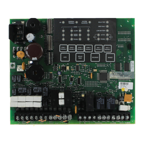
Before You Begin Installing SK-4224 Board Layout Figure 3-1 shows the SK-4224 circuit board including location of terminals, connectors, DIP switches, and LEDs. Annunciator Programming DIP Switches SK-2884 AC Power Connector Serial Interface Connector On-Board Piezo Sounder Backup Battery Connector... -
Page 11: Electrical Specifications
32° - 120° F (0° - 49 ° C) Humidity: 10 - 85% non-condensing It is important to protect the SK-4224 control panel from water. To prevent water damage, the following conditions should be AVOIDED when mounting the units: •... -
Page 12: Mounting The Sk-4224
Before You Begin Installing Mounting the SK-4224 Read the environmental specifications in Section 3.5 before mounting the cabinet. The panel should be accessible to main drop wiring runs. It should be mounted as close to the center of the building as possible and located within a secured area, but should be accessible for testing and service. -
Page 13: Assembly
1. Remove keys from the envelope taped to the top of the cabinet. 2. Unlock the cabinet door. 3. Remove the packing material and the SK-4224 components. 4. Snap the bezel into the opening in the front of the cabinet. See Figure 3-3. -
Page 14: Wiring Specifications
Before You Begin Installing Wiring Specifications Induced noise (transfer of electrical energy from one wire to another) can cause false alarms or interfere with control panel operation in other ways. To avoid induced noise, follow these guidelines: • Isolate input wiring from high current output and power wiring. Do not pull one multi- conductor cable for the entire panel. -
Page 15: Calculating Current Draw And Standby Battery
Standby, 5 mins. Alarm 7 AH 270 mA 110 mA 12 AH 425 mA 170 mA Note: Batteries greater than 7 AH must be installed in a Silent Knight AB-33 or any enclosure UL listed for Fire Protective Signaling. 151068 firealarmresources.com... -
Page 16: Current Draw Worksheet
For each device, use this formula: This Column X This column Current per number of devices Standby: 65 mA 65 mA SK-4224 Panel Alarm: 250 mA 250 mA Current Subtotals: 65 mA 250 mA Refer to device manual for current ratings. See Appendix to this manual for Smoke Detectors max. - Page 17 Model SK-4224 Fire Alarm Control Panel Installation/Operation Manual 3-10 151068 firealarmresources.com...
-
Page 18: Hardware Installation
Section 4 Hardware Installation AC Power At installation, connect the transformer AC inputs to the AC power source as shown in Figure 4-1. It may be necessary for a professional electrician to make this connection. The AC inputs are rated as 120 VAC, 60 Hz (for transformer P/N 115061) or 230 VAC, 50 Hz (for transformer P/N 115031). -
Page 19: Battery Connection
Model SK-4224 Fire Alarm Control Panel Installation/Operation Manual Battery Connection The SK-4224 battery charge capacity is 7.0 AH. Use two Model 12 VDC batteries of the same AH rating. Determine the correct AH rating as per your current load calculation (see Table 3- Wire batteries in series to produce a 24-volt equivalent. -
Page 20: Initiating Circuit Installation
The figure uses Silent Knight’s SLK-24F with HSB-224 base as an example. You can use any detector that has been UL listed for compatibility with the SK-4224. Refer to the Appendix for a list of compatible devices. Refer to Section 6 for configuration options. -
Page 21: Class A Smoke Detector Installation
4.3.3 Class A Smoke Detector Installation Figure 4-5 illustrates how to connect a UL listed smoke detector to the SK-4224 in a Class A configuration. Refer to the Appendix for a list of compatible devices. Information on selecting zone configuration options is in Section 6. -
Page 22: Four-Wire Smoke Detector
Figure 4-6 shows how to connect four-wire smoke detectors to the SK-4224 initiating circuits. The figure uses Silent Knight’s SLK-24F with HSC-4R base as an example. You can use any UL listed device. Refer to the Appendix for a list of compatible devices. Information on selecting zone configuration options is in Section 6. -
Page 23: Notification Appliance Circuit Installation
Notification appliances used with the SK-4224 must be UL listed for compatibility with the SK-4224. Refer to the Appendix at the end of this manual for a list of compatible appliances. For proper operation, you must use polarized notification appliances with a model 7628 4.7k ohm end-of-line (EOL) resistor on each circuit. -
Page 24: Class A Notification Appliance Circuit Installation
Each relay has three terminals (N.O., Common, and N.C.). Refer to Figure 3-1 for location of these terminals. Auxiliary Power Circuit The SK-4224 has a power limited auxiliary power circuit which can source up to .5A. The terminal is labeled “AUX PWR”. Refer to Figure 3-1 for location of this terminal. 151068... -
Page 25: Door Release Wiring
Model SK-4224 Fire Alarm Control Panel Installation/Operation Manual Door Release Wiring Figure 4-9 shows how to configure a door release using an ESL DH series door holder. Door Holder ESL DHX 1224 Figure 4-9 Door Release Wiring 151068 firealarmresources.com... -
Page 26: Optional Accessories Installation
1. Unplug the AC power connector from the SK-4224 control panel. See Figure 4-1. 2. Unplug the battery connector from the SK-4224 control panel. See Figure 4-2. 3. Plug the SK-2884 Serial board on SK-4224 control panel by aligning the 4-pin connector and the three stand-offs with their respective receptors. See Figure 4-10. -
Page 27: Wiring The Sk-2884 To An Expansion Device
Model SK-4224 Fire Alarm Control Panel Installation/Operation Manual Wiring the SK-2884 to an Expansion Device The SK-2884 uses a three wire connection to all of the SK-4224 compatible expansion devices (see Table 3-2). Connect all the expansion devices to the SK-2884 as follows:... - Page 28 Hardware Installation 3. Terminate the wiring as shown in Figure 4-11. See also Table 4-2. SK-2884 SK-2866 Supervised Power Limited Figure 4-11 SK-2866 Connection to the SK-2884 Table 4-2: SK-2866 Wiring Connections SK-2866 SK-2884 Terminals Terminals D (Data) D (Data) 151068 4-11 firealarmresources.com...
-
Page 29: Setting The Sk-2866'S Address
Model SK-4224 Fire Alarm Control Panel Installation/Operation Manual Setting the SK-2866’s address The range of valid addresses is 0-3. Each device requires a unique address. Set the DIP switches as shown in Table 4-3. See also Figure 4-11. Table 4-3: SK-2866 Addresses Per DIP Switch Setting... -
Page 30: 2880 Installation
Hardware Installation 4.7.3 SK-2880 Installation The SK-2880 is an Input/Output module. The SK-2880 has 34 pre-defined open collector outputs (see Table 4-6) that can be used to drive LEDs, interface with other controls or systems, or control one of the three built-in Form C relays. See Figure 4-13, Figure 4-15 and Figure 4-16. -
Page 31: Connecting The Sk-2880 To The Sk-2884
Model SK-4224 Fire Alarm Control Panel Installation/Operation Manual 4.7.3.1 Connecting the SK-2880 to the SK-2884 The control panel communicates to the I/O module through the Serial Interface Board (see also Section 4.7.1). Figure 4-14 illustrates how to properly wire the I/O module to the Serial Interface Board. -
Page 32: Open Collector Outputs (P1, P2, And P3)
Hardware Installation 4.7.3.3 Open Collector Outputs (P1, P2, and P3) Each pin on the Pin Connectors (P1, P2, and P3) have a predefined output. Table 4-6 lists the Pin Connectors and describes what each pin outputs. Table 4-6: Pin-outs for Open Collector Outputs Pin Number Output Description... -
Page 33: Wiring Sk-2880 Open Collector Outputs
Model SK-4224 Fire Alarm Control Panel Installation/Operation Manual Table 4-6: Pin-outs for Open Collector Outputs Pin Number Output Description Connector Pin 1 NAC 1 Trouble Outputs when a trouble condition exists on NAC 1. Pin 2 NAC 2 Trouble Outputs when a trouble condition exists on NAC 2. -
Page 34: 2880 Input Switches And Relay Wiring
Hardware Installation 4.7.3.4 SK-2880 Input Switches and Relay Wiring This section describes the components of terminal strip 2 (see Figure 4-13) on the SK-2880. Terminal strip 2 provides two input switches (Reset & Silence) and three Form C relays. Figure 4-16 illustrates how to configure the inputs switches and the Form C Relays. Any Open Collector Output Listed... -
Page 35: Mounting The Sk-2880
Model SK-4224 Fire Alarm Control Panel Installation/Operation Manual 4.7.3.5 Mounting the SK-2880 The I/O module must be mounted by itself inside a UL Listed (for Fire Protective Signal) accessory cabinet. Follow these steps to mount the SK-2880: 1. Remove the SK-2880’s cover. A small screw driver can be used. -
Page 36: Notification Expansion Mode
FACP input of the SK-4224, which can trigger the SK-4224 circuits when the host panel goes into alarm. Note: The SK-4224 does not go into the alarm state when the host control panel triggers the SK-4224’s notification appliance circuits. -
Page 37: Class B Notification Expansion Wiring
The host fire alarm control panel may use an EOL with a value other than 4.7 KΩ, used by the SK-4224. In this case, use an UL listed EOL for the host panel you are using. Figure 5-2 Class B Supervised Notification Expansion Configuration 151068 firealarmresources.com... -
Page 38: System Configuration
Section 6 System Configuration To configure the SK-4224 system set the DIP switch that controls the option you want to select. The following chart shows how to program the DIP switches that control system, zone, and notification appliance operation. Refer to Figure 3-1 for location of the DIP switches. - Page 39 Model SK-4224 Fire Control Panel Installation/Operation Manual Table 6-1: System Configuration To Enable For Entire Panel (DIP 3) DIP Position ON = Serial Annunciator connected to the control panel. OFF = No Serial Annunciator connected to the control panel. Serial Accessory Devices ON = Serial DACT connected to the control panel OFF = No Serial DACT connected to the control panel.
-
Page 40: System Operation
Section 7 System Operation The annunciator on the SK-4224 board is used for all system operation. It contains the switches for enabling silencing, resetting, and so on. The LEDs that indicate system status are also located on the annunciator. Figure 7-1 On-Board Annunciator Meaning of LEDs The chart below explains the meaning of LEDs on the system board. - Page 41 Model SK-4224 Fire Alarm Control Panel Installation/Operation Manual Table 7-1: Meaning of LEDs LED (Color) Function Comments GND FAULT (yellow) ON = Ground fault condition exists and was acknowledged If flashing, press the ACK button to acknowledge the condition. OFF = No fault...
-
Page 42: Operation Keys (Switches)
System Operation Operation Keys (Switches) All system operations are performed from the on-board keys (switches) as described in the chart below. Table 7-2: Operations and Instructions Operation Keystrokes Disable notification appliance circuit. Press the appropriate [NAC DISABLE] key. The NAC circuit will be disabled and the corresponding TROUBLE LED will Double Flash. - Page 43 Model SK-4224 Fire Alarm Control Panel Installation/Operation Manual 151068 firealarmresources.com...
-
Page 44: Appendix A Compatible Devices
Compatible Devices This section of the manual lists devices (smoke detectors and notification appliances) that are compatible with the SK-4224. Contact Silent Knight if you have a question about whether a device not listed here is compatible. A.1 Smoke Detectors This section of the manual contains information about smoke detectors that are compatible with the SK-4224. -
Page 45: Two-Wire Smoke Detectors
Model SK-4224 Fire Alarm Control Panel Installation/Operation Manual A.1.2 Two-Wire Smoke Detectors The table below lists two-wire smoke detectors that are compatible with the SK-4224. The columns show the number of detectors per circuit that can be used. The two-wire compatibility identifier is 24F. - Page 46 Compatible Devices Table A-1: Compatible Two-Wire Smoke Detectors Enhance Model Name or Number Compatibility ID Manufacturer Mode (Base model name or number in # per Circuit Compatible parentheses.) Head Base FDT1 Falcon 525T FDT1 301I-DH (301DH-2) 301I (301B) 301IL (301BL / SS B401BH) 301P (301B) 301P (301DH-2) 301PL (301BL / SS B401BH)
- Page 47 Model SK-4224 Fire Alarm Control Panel Installation/Operation Manual Table A-1: Compatible Two-Wire Smoke Detectors Enhance Model Name or Number Compatibility ID Manufacturer Mode (Base model name or number in # per Circuit Compatible parentheses.) Head Base 2300 20 / loop...
- Page 48 Compatible Devices Table A-1: Compatible Two-Wire Smoke Detectors Enhance Model Name or Number Compatibility ID Manufacturer Mode (Base model name or number in # per Circuit Compatible parentheses.) Head Base 612H (4B, 6B, M612/912) 612H 4B, 6B, M612/912 612HP (4B, 6B, M612/912) 612HP 4B, 6B, M612/912...
-
Page 49: Four-Wire Smoke Detectors
Model SK-4224 Fire Alarm Control Panel Installation/Operation Manual Four-Wire Smoke Detectors Table A-2: Compatible Four-Wire Smoke Detectors Manufacturer Model Silent Knight SD-P24F with SD-B4@ base Detection Systems DS200/DS200HD MB200 445 Series 449 Series Gentex 2040-24 Power Supervision Unit System Sensor... -
Page 50: Notification Appliances
Compatible Devices A.2 Notification Appliances The chart below lists notification appliances compatible with the SK-4224. Note: Units that operate at 12 or 24 VDC must be selected for 24 VDC operation. Table A-3: Compatible Notification Appliances Manufacturer Model Type 446X 12/24VDC... - Page 51 Model SK-4224 Fire Alarm Control Panel Installation/Operation Manual Table A-3: Compatible Notification Appliances Manufacturer Model Type 6243B-0-14-24-DC Electron-Mechanical Horn (flush) 6244B-0-14-24-DC Electron-Mechanical Horn (surface) 6245B-0-4-24-DC Electron-Mechanical Horn (ceiling) 6246B-( )-14-24-DC Electron-Mechanical Horn/Strobe (flush) 6247B-( )-14-24-DC Electron-Mechanical Horn/Strobe (surface) 6248B-( )-4-24-DC...
- Page 52 Compatible Devices Table A-3: Compatible Notification Appliances Manufacturer Model Type P2475K-FC Horn/Strobe P24110-FC Horn/Strobe P24110W-FC Horn/Strobe P24110K-FC Horn/Strobe S2415-FC Strobe S241575-FC Strobe S241575W-FC Strobe S241575K-FC Strobe S2430-FC Strobe FCI (Cont.) S2430W-FC Strobe S2430K-FC Strobe S2475-FC Strobe S2475W-FC Strobe S2475K-FC Strobe S24110-FC Strobe S24110W-FC...
- Page 53 Model SK-4224 Fire Alarm Control Panel Installation/Operation Manual Table A-3: Compatible Notification Appliances Manufacturer Model Type MASS241 Horn/Strobe MASS24110ADA Horn/Strobe MASS2415ADA Horn/Strobe MASS2475ADA Horn/Strobe SS4110ADA Strobe SS2415ADA Strobe SS2475ADA Strobe PS2415ADA Mini-Horn/Strobe PS241575ADA Mini-Horn/Strobe PS24110ADA Mini-Horn/Strobe PS2475ADA Mini-Horn/Strobe P2415 Horn/Strobe...
- Page 54 Compatible Devices Table A-3: Compatible Notification Appliances Manufacturer Model Type 46T-G4-24-R Bell 46T-G6-24-R Bell 46T-G10-24-R Bell 46T-G6-24-WS-24-HF-R Strobe/Bell 46T-G10-24-WS-24-HF-R Strobe/Bell 46T-G6-24-WH-24-HF-R Strobe/Bell 46T-G10-24-WH-24-HF-R Strobe/Bell 7001T-12\24-W-FR Strobe Horn 7002T-12\24-W-FR Strobe Horn AES-DL1-R Multitone Horn AES-EL1-R Multitone Horn AES-DL1-WS-24-VF-R Multitone Horn AES-EL1-WS-24-VF-R Multitone Horn AES-DL1-WH-24-VF-R Multitone Horn...
- Page 55 Model SK-4224 Fire Alarm Control Panel Installation/Operation Manual Table A-3: Compatible Notification Appliances Manufacturer Model Type AS2430C-FW Audible Strobe AS2475C-FW Audible Strobe AS24100C-FW Audible Strobe AS-2415-VFR Strobe Horn AS-241575-VFR Strobe Horn AS-2430-VFR Strobe Horn AS-2475-VFR Strobe Horn AS-24110-HFR Strobe Horn...
- Page 56 Compatible Devices Table A-3: Compatible Notification Appliances Manufacturer Model Type CH-DF1-WS-24-VF-R Strobe Chime DSM-12/24 Sync Module EH-DL1-R Electronic Horn EH-EL1-R Electronic Horn Electronic Horn EHS-DL1-W-VF-R Strobe Horn (single input) EHS-EL1-W-VF-R Strobe Horn (single input) EH-DL1-WS-24-VF-R Strobe Horn (dual input) EH-EL1-WS-24-VF-R Strobe Horn (dual input) EH-DL1-WH-24-VF-R Strobe Horn (dual input)
- Page 57 Model SK-4224 Fire Alarm Control Panel Installation/Operation Manual Table A-3: Compatible Notification Appliances Manufacturer Model Type MIZ-24-HSW-HFR Mini-Horn/Strobe MIZ-24-IS-VFR Mini-Horn/Strobe MIZ-24-WS-VF-R Mini-Horn/Strobe MIZ-24-WS-VF-W Mini-Horn/Strobe MIZ-24-WH-VF-W Mini-Horn/Strobe MIZ-24-WM-VF-W Mini-Horn/Strobe MT-12/24-R Strobe Horn MT4-12/24-R Multitone Appliance MT4-115-R Multitone Appliance MT-24-LS-VFR Strobe Horn...
- Page 58 Compatible Devices Table A-3: Compatible Notification Appliances Manufacturer Model Type RS-24110-HFR Strobe RSP-24110-HFR Strobe RSS-2415W-FR Strobe RSS-241575W-FR Strobe RSS-2430W-FR Strobe RSS-2475W-FR Strobe RSS-24110W-FR Strobe RSS-2415C-FW Strobe RSS-2430C-FW Strobe RSS-2475C-FW Strobe RSS-24100C-FW Strobe RSSP-2415W-FR Strobe RSSP-241575-FR Strobe RSSP-2430W-FR Strobe RSSP-2475W-FR Strobe RSSP-24110W-FR Strobe SL-24-VFR...
- Page 59 Model SK-4224 Fire Alarm Control Panel Installation/Operation Manual Table A-3: Compatible Notification Appliances Manufacturer Model Type WS1T-24-FR Strobe Wheelock WS3T-24-FR Strobe (Cont.) WST-24-FR Strobe A-16 151068 firealarmresources.com...
- Page 60 SK-4224 Basic Operating Instructions P/N 151066 These instructions must be framed and displayed next to the SK-4224 panel in accordance with NFPA 72 fire code for Local Fire Alarm System. LED (Color) Function Comments AC (green) ON = Good AC If flashing press the ACK button to acknowledge the condition.
- Page 61 firealarmresources.com...
- Page 62 Repair and RA Procedure • All products that are returned to Silent Knight for credit or repair require a RA (Return Authorization) number. Call Silent Knight Customer Service at 800-446-6444 or 763-493- 6435 between 8:00 A.M. and 4:45 P.M. CST, Monday through Friday to obtain a return authorization number.
- Page 63 Upon return of the defective product, Silent Knight will at its sole discretion, either repair or replace, at no cost, such goods as may be of defective material or workmanship. Customers outside the United States are to return products to their distributor for repair.
- Page 64 7550 Meridian Circle Maple Grove, MN 55369-4927 763-493-6455 1-800-328-0103 Fax: 763-493-6475 © 2002 Silent Knight Part Number 151068D, 02/02 firealarmresources.com...
Need help?
Do you have a question about the SK-4224 and is the answer not in the manual?
Questions and answers