SILENT KNIGHT INTELLIKNIGHT 5700 Installation And Operation Manual
Addressable fire control panel
Hide thumbs
Also See for INTELLIKNIGHT 5700:
- Installation and operation manual (186 pages) ,
- Installation and operation manual (184 pages) ,
- Basic operating instructions (1 page)

Related Manuals for SILENT KNIGHT INTELLIKNIGHT 5700


Summary of Contents for SILENT KNIGHT INTELLIKNIGHT 5700
- Page 1 INTELLIKNIGHT MODEL 5700 Addressable Fire Control Panel Installation and Document 151295 Operations Manual 08/27/09 Rev: P/N 151295: K ECN 09-570...
-
Page 3: Installation Procedure
Do not tighten screw terminals more than 9 in-lbs. Over-tightening may damage threads, resulting in reduced terminal contact pressure and difficulty with screw terminal removal. Silent Knight fire alarm control panels contain static-sensitive components. Always ground yourself with a proper wrist strap before handling any circuits so that static charges are removed from the body. - Page 4 substitute for fire insurance! An automatic fire alarm system - typically made up of smoke detectors, heat detectors, manual pull stations, audible warning devices, and a fire alarm control with remote notification capability - can provide early warning of a developing fire. Such a system, however, does not assure protection against property damage or loss of life resulting from a fire.
-
Page 5: Table Of Contents
1.1.2 Software Features ..........................1-2 About this Manual ............................ 1-2 1.2.1 Terms Used in this Manual ....................... 1-2 Compatible Products ..........................1-3 How to Contact Silent Knight ........................1-5 Section 2 Agency Listings, Approvals, and Requirements ........2-1 Federal Communications Commission (FCC) ..................2-1 Underwriters Laboratories (UL) ...................... - Page 6 Model 5700 Installation and Operation Manual Section 4 Control Panel Installation ...................... 4-1 Mounting the Control Panel Cabinet ....................... 4-1 4.1.1 Preventing Water Damage ........................ 4-1 4.1.2 Removing the 5700 Assembly from the Housing ................4-1 4.1.3 Dead Front Installation and removal ....................4-1 4.1.3.1 Installing the Dead Front ......................
- Page 7 6.2.2 Output Circuit Mapping ........................6-6 6.2.3 Zone Event Mapping ........................6-7 6.2.4 Mapping LED Points ........................6-9 Programming Using the 5660 Silent Knight Software Suite ..............6-10 Programming Using an Annunciator ..................... 6-10 6.4.1 Entering / Exiting the Program Menu ..................... 6-11 6.4.2 Moving through the Menus ......................
- Page 8 Model 5700 Installation and Operation Manual Zone ................................. 7-5 7.4.1 Edit Zone ............................7-5 7.4.1.1 Edit Zone Name ........................7-5 7.4.1.2 Edit Zone Properties ....................... 7-6 7.4.1.3 Zone Outputs .......................... 7-8 7.4.1.4 Cadence Patterns ........................7-11 7.4.2 Add Zone ............................7-12 7.4.3 Delete Zone .............................
- Page 9 Contents 7.10 Access Codes ............................7-42 7.10.1 Profile Edit Menu ..........................7-43 7.10.1.1 Edit Name ..........................7-43 7.10.1.2 Edit Access Code ......................... 7-43 7.10.1.3 Panel Functions ........................7-43 Section 8 System Operation ..........................8-1 Annunciator Description .......................... 8-1 8.1.1 LCD Displays ........................... 8-1 8.1.2 Banner ...............................
- Page 10 Section 11 Installation Records ........................11-1 11.1 Detector and Module Point Record ......................11-1 Appendix A Compatible Devices ........................A-1 Appendix B Special Characters Lists ......................B-1 Silent Knight Fire Product Warranty and Return Policy Model 5700 Basic Operating Instructions 151295...
-
Page 11: Introduction
Section 1 Introduction The 5700 Fire Alarm Control / Communicator is an addressable fire control system that meets the requirements of UL 864. Overview of Basic System 1.1.1 Hardware Features • The 5700 has one signaling line circuit (SLC) that supports 50 SK detectors and 50 SK modules or 50 Hochiki protocol devices. -
Page 12: Software Features
Model 5700 Installation and Operation Manual 1.1.2 Software Features • Advanced smoke detector features: –Automatic drift compensation –Maintenance alert region –Point status eliminates calibrated smoke test requirements for NFPA 72 • “JumpStart” feature for easy programming • Non-volatile event history stores 1000 events •... -
Page 13: Compatible Products
Introduction Compatible Products The chart below lists the products available from Silent Knight for use with the 5700. Type of Model Description Device See Section 5.1 for a list of compatible devices. Addressable SLC Devices Hochiki See Section 5.2 for a list of compatible devices. - Page 14 Model 5700 Installation and Operation Manual The following modems have been tested by Silent Knight for compatibility with the 5700 and the Silent Knight Software Suite software packages: Table 1-1: Compatible Modems Manufacturer Model US Robotics 28.8 Motorola LifeStyle 28.8, 3400 series Premier 33.6...
-
Page 15: How To Contact Silent Knight
How to Contact Silent Knight If you have a question or encounter a problem not covered in this manual, contact Silent Knight Technical Support at 800-446-6444. To order parts, contact Silent Knight Sales at 800-328-0103 or 203-484-7161 in Connecticut. 151295... - Page 16 Model 5700 Installation and Operation Manual Limitations of Fire Alarm Systems Manufacturer recommends that smoke and/or heat detectors be located throughout a protected premise following the recommendations of the current edition of the National Fire Protection Association Standard 72 (NFPA 72), manufacturer’s recommendations, State and local codes, and the recommendations contained in Guide for the Proper Use of System Smoke Detectors, which is made available at no charge to all installing dealers.
- Page 17 Introduction heat on their sensors increases at a predetermined rate or reaches a predetermined level. Heat detectors are designed to protect property, not life. • Warning devices (including horns, sirens, and bells) may not alert people or wake up sleepers who are located on the other side of closed or partially open doors. A warning device that activates on a different floor or level of a dwelling or structure is less likely to awaken or alert people.
- Page 18 Model 5700 Installation and Operation Manual Requirements and recommendations for proper use of fire alarm systems in- cluding smoke detectors and other fire alarm devices: Early fire detection is best achieved by the installation and maintenance of fire detection equipment in all rooms and areas of the house or building in accordance with the requirements and recommendations of the current edition of the National Fire Protection Association Standard 72, National Fire Alarm Code (NFPA 72), the manufacturer’s recommendations, State and local codes and the recommendations contained in Guide for the Proper Use of...
-
Page 19: Agency Listings, Approvals, And Requirements
NFPA 72. Federal Communications Commission (FCC) The following information must be provided to the telephone company before the 5700 can be connected to the phone lines: Manufacturer: Silent Knight Model Number: 5700 FCC registration number: US: AC6AL05B205700 Ringer equivalence: 0.5B... - Page 20 If trouble is experienced with this equipment 5700, for repair or warranty information, please contact Silent Knight (see Section 1.4). If the equipment is causing harm to the telephone network, the telephone company may request that you disconnect the equipment until the problem is resolved.
-
Page 21: Underwriters Laboratories (Ul)
Agency Listings, Approvals, and Requirements j) If your home has specially wired alarm equipment connected to the telephone line, ensure the installation of this 5700 does not disable your alarm equipment. If you have questions about what will disable alarm equipment, consult your telephone company or qualified installer. -
Page 22: Requirements For Central Station Fire Alarm Systems
Model 5700 Installation and Operation Manual 2.2.2 Requirements for Central Station Fire Alarm Systems 1. Use both phone lines. Enable phone line monitors for both lines. 2. You must program a phone number and a test time so that the 5700 sends an automatic daily test to the central station. -
Page 23: Before You Begin Installing
Section 3 Before You Begin Installing This section of the manual is intended to help you plan your tasks to facilitate a smooth installation. Please read this section thoroughly, especially if you are installing a 5700 panel for the first time. What’s in the Box? The 5700 ships with the following hardware: •... -
Page 24: Electrical Specifications
Model 5700 Installation and Operation Manual Electrical Specifications Table 3-1 list the terminal block on the 5700 as well as a description of the each individual terminal and their respective electrical rating. For location of the terminals refer to Figure 3-2. See also Section 4 for installation. -
Page 25: Wiring Specifications
Before You Begin Installing Wiring Specifications Induced noise (transfer of electrical energy from one wire to another) can interfere with telephone communication or cause false alarms. To avoid induced noise, follow these guidelines: • Isolate input wiring from high current output and power wiring. Do not pull one multi- conductor cable for the entire panel. -
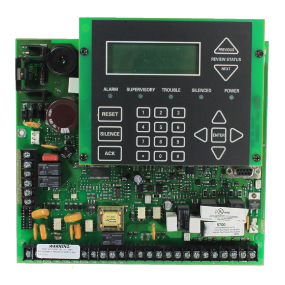
Page 26: Board Assembly Diagram
Model 5700 Installation and Operation Manual Board Assembly Diagram On-board Annunciator 120 VAC, 60 Hz, 1.5A AC Power Input Programming Port Form C Relays Terminal Block 2 Battery Connector Terminal Block 1 24 VDC Phone Lines SLC In/Out, NAC/Aux SLC Programming Power Circuits SBUS Form C... -
Page 27: Calculating Current Draw And Standby Battery
If the current is above 2.5 A you will need to use a notification power expander(s) such as the Silent Knight 5496 intelligent power module, to distribute the power loads so that the 5700 or the power expanders do not exceed their power rating. Refer to the current draw worksheets provided with the 5496 manual so you do not exceed their power require- ments. -
Page 28: Current Draw Worksheet For Sk Slc Devices
Model 5700 Installation and Operation Manual 3.6.1.1 Current Draw Worksheet for SK SLC Devices Use Table 3-2 to determine current requirements during alarm/battery standby operation when SK SLC devices are installed. (Copy the page if additional space is required.) You can install up to 50 SK detectors and 50 SK modules. - Page 29 Before You Begin Installing Table 3-2: Current Calculation Worksheet for SK Devices Standby Alarm Device # of Devices Current per Device Current Current Addressable SLC Modules Standby/ 0.375 mA Alarm: 0.375 mA SK-Control Standby/ 1.7 mA Aux Pwr Alarm: 7 mA SK-Monitor SK-Minimon Standby/Alarm...
- Page 30 Model 5700 Installation and Operation Manual Table 3-2: Current Calculation Worksheet for SK Devices Standby Alarm Device # of Devices Current per Device Current Current 5865-4 LED Annunciator Standby: 35 mA Alarm: 145 mA (with reset and silence switches) Standby: 35 mA (8 max.) 5865-3 LED Annunciator...
-
Page 31: Current Draw Worksheet For Hochiki Slc Devices
Before You Begin Installing 3.6.1.2 Current Draw Worksheet for Hochiki SLC Devices Use Table 3-3 to determine current requirements during alarm/battery standby operation when Hochiki SLC devices are installed. (Copy the page if additional space is required). Table 3-3: Current Calculation Worksheet for Hochiki Devices Standby Alarm Device... - Page 32 Model 5700 Installation and Operation Manual Table 3-3: Current Calculation Worksheet for Hochiki Devices Standby Alarm Device # of Devices Current per Device Current Current Accessories Modules Standby: 20 mA 5860 Remote Fire Alarm (8 max.) Annunciator Alarm: 25 mA 5824 Serial / Parallel Module (2 max.) Standby/Alarm:...
-
Page 33: Maximum Battery Standby Load
Warning! Silent Knight does not support the use of batteries smaller than those listed in table above. If you use a battery too small for the installation, the system could overload the battery resulting in the installation having less than the required 24 hours standby power. - Page 34 Model 5700 Installation and Operation Manual 3-12 151295...
-
Page 35: Control Panel Installation
Section 4 Control Panel Installation Caution! To avoid the risk of electrical shock and damage to the unit, power should be OFF at the control panel while installing or servicing. Mounting the Control Panel Cabinet Read the environmental specifications in Section 3.2 before mounting the 5700 panel. The 5700 cabinet dimensions are: 12-3/4”... -
Page 36: Installing The Dead Front
Model 5700 Installation and Operation Manual 4.1.3.1 Installing the Dead Front Follow these steps to properly install the dead front panel into the control panel cabinet. 1. Remove the top two annunciator screws, do not discard them they will be reused. See Figure 4-1 for annunciator screw location. -
Page 37: Ac Connection
Control Panel Installation AC Connection At installation, connect the AC terminals to the power source as shown in Figure 4-2. It may be necessary for a professional electrician to make this connection. The AC terminals are rated at 120 VAC, 60 Hz, 1.5A. Supervised To AC Ground... -
Page 38: Battery Connection
Model 5700 Installation and Operation Manual Battery Connection The control panel battery charge capacity is 7.0 to 35 AH. The main control cabinet can house batteries up to 7 AH, larger capacity batteries can be housed in a Remote Battery Box (P/N RBB). -
Page 39: Rbb Accessory Cabinet
Control Panel Installation 4.3.1 RBB Accessory Cabinet The Model RBB Accessory cabinet can be used when your backup batteries requirements use backup batteries that are too large to fit into the main control panel cabinet. The RBB cabinet holds batteries up to the 35 AH size. The RBB dimensions are 16" W x 10" H x 6" D (40.64 cm W x 25.4 cm H x 15.24 cm D). - Page 40 Model 5700 Installation and Operation Manual 3. Run extended battery cable from control panel cabinet through conduit to RBB cabinet. See Figure 4-6. RBB Cabinet Cover Screws Conduit Coupler Conduit RBB Cabinet Cover Screws Figure 4-6 Battery Connections in the RBB Cabinet Note: Figure 4-6 is an example of how the wire connections can be routed.
-
Page 41: Sbus Wiring
Control Panel Installation SBUS Wiring This section contains information on calculating SBUS wire distances and the types of wiring configurations (Class B). 4.4.1 Calculating Wiring distance for SBUS modules The following instructions will guide you in determining the type of wire and the maximum wiring distance that can be used with control panel SBUS accessory modules. - Page 42 Model 5700 Installation and Operation Manual These cases are marked in the chart with an asterisk (*). Maximum length can never be more than 6,000 feet, regardless of gauge used. (The formula used to generate this chart is shown in the note below).
- Page 43 Control Panel Installation Wiring Distance calculation example: Suppose a system is configured with the following SBUS modules: 2 - Module 5860 Fire Annunciator 1 - 5496 Notification Power Expander 1 - 5865 LED Fire Annunciator 1 - 5824 Parallel/Serial Interface The total worst case current is calculated as follows: 5860 Current Draw = 2 x .100 amps...
-
Page 44: Wiring Configurations
Model 5700 Installation and Operation Manual 4.4.2 Wiring Configurations Figure 4-8 illustrates Class B configuration. Supervised Power Limited Figure 4-8 SBUS Class B Wiring 4.4.2.1 How to Power SBUS Devices From Auxiliary Power Supply Figure 4-9 illustrates how to power SBUS devices from an Auxiliary Power Supply such as the 5495 or 5499, when the maximum number of SBUS devices exceeds the SBUS power requirments. -
Page 45: Remote Annunciator 5860 Installation
Control Panel Installation Remote Annunciator 5860 Installation The optional Model 5860 Remote Annunciator, shown in Figure 4-10, performs the same functions as the on-board annunciator. Operation is identical. Up to 8 annunciators can be added to the 5700 system. Figure 4-10 Model 5860 Remote Annunciator, Front View 5860 installation involves the following steps: 1. -
Page 46: Mounting The 5860
Model 5700 Installation and Operation Manual 4.5.1 Mounting the 5860 This section of the manual describes mounting the remote annunciator. The annunciator can be flush- or surface-mounted. Figure 4-11 shows the parts of the annunciator. Instructions for disassembling and mounting appear on the following pages. -
Page 47: Flush Mounting
Control Panel Installation The 5860 comes from the factory fully assembled. You must disassemble it for mounting. To disassemble the annunciator, use a 5/64 hex wrench to remove the set screws, located on the bottom of the annunciator bezel. (See Figure 4-12 for location of the set screws.) Figure 4-12 Annunciator Back Box and Bezel Details 4.5.1.1 Flush Mounting This section of the manual describes flush mounting. - Page 48 Model 5700 Installation and Operation Manual Flush Mounting with an Electrical Box The 5860 annunciator can be used with the following types of electrical boxes: 4S, single- gang, and double-gang. If an electrical box is used, the box must be 1-3/8” back from the face of the wall to accommodate the annunciator.
-
Page 49: Surface Mounting
Control Panel Installation 4. After the annunciator wiring to the panel has been completed (described in Section 4.5.2), replace the electronic assembly in the back box. Place the bezel over the back box and tighten the set screws on the bezel. Figure 4-14 Flush Mounting the Back Box 4.5.1.2 Surface Mounting The 5860 can be mounted directly to a surface or can be attached to a single, double, or four-... -
Page 50: Model 5860 Connection To The Panel
Model 5700 Installation and Operation Manual 4.5.2 Model 5860 Connection to the Panel Connect the 5860 to the panel as shown in Figure 4-15. Supervised Power Limited Figure 4-15 Model 5860 Connection to the Panel 5824 Serial/Parallel Printer Interface Module Installation The 5824 serial/parallel printer interface module allows you to connect a printer to the panel, so you can print a real-time log of system events, a report of detector status, and event history. - Page 51 Control Panel Installation 5. Connect a printer to the 5824 as shown in Figure 4-17. Supervised Power Limited Figure 4-16 5824 Connection to the Panel To Parallel Printer To Serial Printer Figure 4-17 Printer Connection 151295 4-17...
-
Page 52: Selecting 5824 Options
Model 5700 Installation and Operation Manual 4.6.1 Selecting 5824 Options Configuring the 5824 includes the following steps: • Add the module to the system. JumpStart will add the module automatically (see Section 6.1). You can also add it manually (see Section 7.3.2). •... -
Page 53: 5880 Led Driver Module
Control Panel Installation 5880 LED Driver Module The 5880 is an LED driver board that can be used in a wide variety of applications, including as an interface with most customized floor plan annunciator boards. The 5880 can drive up to 40 LEDs and has one PZT controller. -
Page 54: Facp Connection
Model 5700 Installation and Operation Manual 4.7.2 FACP Connection The 5880 connects to the panel via the SBUS. Make connections as shown in Figure 4-20. After the 5880 is connected to the panel, it must be added to the system. This programming step is described in Section 4.9. -
Page 55: Led Wiring
Control Panel Installation 4.7.3 LED Wiring There are four 12-pin connectors on the 5880 board for connecting LEDs. Each LED gets its power from Pin 11. Internal resistors are sized so that there is approximately 10 mA of current for each LED, no series resistors are required. LED outputs can be mapped to output circuits. See Section 6 for programming details. -
Page 56: Dry Contact Wiring
Model 5700 Installation and Operation Manual 4.7.4 Dry Contact Wiring The 8 input circuits on the 5880 board are for monitoring switch inputs-any type of switch supported by the control panel can be used with the 5880. For example, you can use a 5880 to monitor pull stations, water flow, tamper, reset, or silence switches. -
Page 57: 5865-3 / 5865-4 Led Annunciator Installation
Control Panel Installation 5865-3 / 5865-4 LED Annunciator Installation The 5865-3 and 5865-4 are LED annunciators. The 5865-4 has 30 mappable LEDs, remote silence and reset key switches, and a general system trouble LED. The 5865-3 has 30 mappable LEDs only. These are arranged as 15 pairs of red (typically used for alarm) and yellow (typically used for trouble) LEDs. -
Page 58: 5865 Mounting
Model 5700 Installation and Operation Manual 4.8.2 5865 Mounting Mount the 5865-4 to a standard 4-gang electrical box. Mount the 5865-3 to a standard 3-gang electrical box. In Figure 4-25, the 5865-4 attached to a 4-gang box is used as an example. Figure 4-25 5865 Mounting Example The 5865 ships with a set of zone description labels that can be inserted into the 5865 board assembly. -
Page 59: Configuring Modules
Control Panel Installation Configuring Modules This section describes how to configure any system hardware modules that have been added to the system. 4.9.1 Assigning Module IDs When installing a hardware module (such as, 5824, 5860, 5496, 5865-3 or 5865-4), you must use the dipswitches on the module to assign an ID# to the module. -
Page 60: Telephone Connection
4.10 Telephone Connection Connect the telephone lines as shown in Figure 4-28. The Model 7860 phone cord is available from Silent Knight for this purpose. A number of programmable options are available for customizing telephone lines. These options are described in Section 7.7. -
Page 61: Notification Appliance/Auxiliary Power Circuits
Control Panel Installation 4.12 Notification Appliance/Auxiliary Power Circuits Two outputs are built-in to the 5700 FACP which can be programmed to be used as NACs (Class A or Class B) or as Aux power. This section of the manual explains how to install conventional notification appliances and how these terminals can be used for auxiliary power. -
Page 62: Class A Notification Wiring
Model 5700 Installation and Operation Manual 4.12.1.2 Class A Notification Wiring You must use an appliance from the list of compatible appliances in the Appendix at the back of this manual. To install a Class A notification appliance circuit: 1. Wire the Class A notification appliances as shown in Figure 4-30. Caution For proper system supervision do not use looped wire under terminals marked –... -
Page 63: Auxiliary Power Installation
Control Panel Installation 4.12.2 Auxiliary Power Installation NAC Circuits 1and 2 on the control panel can be used as auxiliary power circuits. The three types of auxiliary power available are: • Door Holder (see section 4.12.2.1) • Constant (see section 4.12.2.2) •... -
Page 64: Constant Power
Model 5700 Installation and Operation Manual 4.12.2.2 Constant Power Use constant power for applications that require a constant auxiliary power source. Power is always present at Constant circuits. 4.12.2.3 Resettable Power Resettable power is typically used to power beam detectors, flame detectors and conventional 4-wire smoke detectors. -
Page 65: Remote Station Applications
Control Panel Installation 4.14 Remote Station Applications 4.14.1 Keltron Model 3158 Installation The control panel is compatible with Keltron Model 3158, used for direct connection to a Keltron receiver. The 3158 reports alarms, supervisories, and troubles. The 3158 is intended for connection to a polarity reversal circuit of a remote station receiving unit having compatible ratings. -
Page 66: City Box Connection Using The 5220 Module
Model 5700 Installation and Operation Manual 4.14.2 City Box Connection Using the 5220 Module This section describes how to connect the control panel to a municipal fire alarm box or “city box” as required by NFPA 72 Auxiliary Protected Fire Alarm systems for fire alarm service. The city (master) box is an enclosure that contains a manually operated transmitter used to send an alarm to the municipal communication center which houses the central operating part of the fire alarm system. -
Page 67: Nfpa 72 Polarity Reversal
Control Panel Installation 4.14.3 NFPA 72 Polarity Reversal 4.14.3.1 Using the 5220 Module When the 5220 is wired and programmed for polarity reversal, it reports alarm and trouble events to a remote site. Alarms will override trouble conditions and it will not be possible to reset the remote indicator until the condition is cleared and the control panel is reset. - Page 68 Model 5700 Installation and Operation Manual 5. If necessary, adjust loop current using the potentiometer (R10) on the 5220 board. Normal loop current is 2-to-8 mA with a 1k ohm remote station receiving unit. Maximum loop resistance is 3k ohm. Program Relay for Alarm.
-
Page 69: Using The 7644 Module
Control Panel Installation 4.14.3.2 Using the 7644 Module When the 7644 is used for polarity reversal, it allows alarm and trouble events to be reported to a remote site. Alarms will override trouble conditions and it will not be possible to reset the remote indicator until the condition is cleared and the control panel is reset. -
Page 70: Using The Sd500-Arm Addressable Relay Module
Model 5700 Installation and Operation Manual 4.14.4 Using the SD500-ARM Addressable Relay Module When the SD500-ARM is wired for polarity reversal, it reports alarm and trouble events to a remote site. Alarms will override trouble conditions and it will not be possible to reset the remote indicator until the condition is cleared and the control panel is reset. -
Page 71: Using A Mr-201/T Control Relay From Air Products
Control Panel Installation 4.14.5 Using a MR-201/T Control Relay From Air Products When the MR-201/T control relay is wired for polarity reversal, it reports alarm and trouble events to a remote site. Alarms will override trouble conditions and it will not be possible to reset the remote indicator until the condition is cleared and the control panel is reset. -
Page 72: Transmitter Activated By Dry Contacts
Model 5700 Installation and Operation Manual 4.14.6 Transmitter Activated by Dry Contacts This section describes the connection of a UL 864 listed remote station transmitter to the 5700 FACP dry contacts. The FACP contacts must be supervised by the remote station transmitter module using end-of-line resistors (ELRs) with a value determined by the transmitter manufacturer. -
Page 73: Sk And Hochiki Slc Device Installation
Section 5 SK and Hochiki SLC Device Installation Caution! To avoid the risk of electrical shock and damage to the unit, power should be OFF at the control panel while installing or servicing. List of SK SLC Devices The following SK SLC devices can be used with the control panel. See the device installation instructions for more information (packaged with the device). -
Page 74: List Of Hochiki Slc Devices
Model 5700 Installation and Operation Manual List of Hochiki SLC Devices The following Hochiki SLC devices can be used with the control panel. See the appropriate section number in this manual or the device installation instructions (packaged with the device) for more information. Note: The control panel supports the use of either Hochiki SLC devices or SK SLC devices. -
Page 75: Maximum Number Of Devices
SK and Hochiki SLC Device Installation Maximum Number of Devices The 5700 supports SK or Hochiki devices on one 5700 system. The maximum number of devices per system varies depending on device protocol. Device support is as follows: • SK Devices–A 5700 system can support a total of 50 SK detectors and 50 SK modules. •... - Page 76 Model 5700 Installation and Operation Manual The following figures show how length is determined for out and back tap and T-Tap style wiring. Figure 5-1 Calculating wire run length for a simple out and back 151295...
- Page 77 SK and Hochiki SLC Device Installation When using T-taps, the total length of all taps and the main bus must not exceed 40,000 feet. This requirement must be met in addition to the maximum distance requirements for the various wire gauges. Figure 5-2 Calculating Wire Run Length for a T-tap 151295...
-
Page 78: Wiring Slc Devices In Style 6 & 7 (Class A) Configuration
Model 5700 Installation and Operation Manual 5.4.2 Wiring SLC Devices in Style 6 & 7 (Class A) Configuration The following figure illustrates how to wire the SLC loop for Style 6 or Style 7 Class A installations. Note: Style 6 does not use short circuit isolator devices. Figure 5-3 Class A SLC Configuration Note: No t-taps allowed on class A SLC loops. -
Page 79: Wiring Sk Slc Detectors
SK and Hochiki SLC Device Installation Wiring SK SLC Detectors This section describes how to install heat and smoke detectors. All detectors ship with installation instructions. Refer to the detector’s installation instructions for more detailed information. This information applies to the following SK models: •... -
Page 80: Addressing Sk Slc Devices
Model 5700 Installation and Operation Manual Addressing SK SLC Devices All SK devices are addressed using the two rotary dials that appear on the device board. Use the ONES rotary dial to set the ones place in a one or two digit number, and use the TENS rotary dial to set the tens place in a two digit number. -
Page 81: Wiring Hochiki Detectors
SK and Hochiki SLC Device Installation Wiring Hochiki Detectors The information in this section applies to the following Hochiki models: SD505-AHS Heat Detector, SD505-AIS Ionization Smoke Detector, and SD505-APS Photoelectric Smoke Detector. To wire SD505-APS, SD505-AHS, or SD505-AIS detectors: 1. Wire device bases as shown in Figure 5-6. 2. -
Page 82: Addressing Hochiki Devices
Model 5700 Installation and Operation Manual Addressing Hochiki Devices This section tells how to address detectors and modules. 5.8.1 SD505-APS, SD505-AHS, & SD505-AIS The SD505-APS photoelectric smoke detector, SD505-AHS heat detector, and SD505-AIS ionization smoke detector are easily addressed at the FACP. The Installer Code is required to perform this task. - Page 83 SK and Hochiki SLC Device Installation for Seq. Programming. Use to program more than one detector in sequential order. 7. If you are changing addresses, write the programmed address on the back of the device. 8. To exit press left arrow until fully exited. 151295 5-11...
-
Page 84: Hochiki Slc Devices With Dip Switches
Model 5700 Installation and Operation Manual 5.8.2 Hochiki SLC Devices with Dip Switches Input and relay module addresses are set using the dip switches on the module board. The chart below shows the available addresses. For example, to select address 3, place dip switches 1 and 2 in the up position. -
Page 85: Programming Overview
Section 6 Programming Overview This section of the manual is intended to give you an overview of the programming process. Please read this section of the manual carefully, especially if you are programming the control panel for the first time. The JumpStart feature automates many programming tasks and selects default options for the system. -
Page 86: Input Points
Model 5700 Installation and Operation Manual 6.1.1 Input Points JumpStart will determine the number and type of input points (detectors or contact monitor modules) on each SLC loop. JumpStart assigns the correct detector type (heat, or photoelectric), so the installer does not need to edit device type for detectors. Any contact monitor modules on the system will be assigned type “Manual Pull.”... - Page 87 Programming Overview 5. When the message “Configuring System Done” displays, press any key to continue. 6. Select one of the following options from the menu that displays. - Review System Press if you need to review the JumpStart configuration. - Repeat JumpStart Press if you need to rerun JumpStart for any reason.
-
Page 88: Mapping Overview
Model 5700 Installation and Operation Manual Mapping Overview This section of the manual is an overview of mapping. Details about how to select mapping options appear in the appropriate subsections in Section 7. Mapping is an important concept with the control panel. In general terms, mapping is assigning or linking events to outputs that should activate when events occur. -
Page 89: Input Point Mapping
Programming Overview 6.2.1 Input Point Mapping Input points are assigned to input zones. Any input point can be assigned to any input zone. (Input points can be assigned to one zone only. An input point can be designated as “Unused,” which means it has not been assigned to a zone.) Figure 6-2 Input Point Assignment Example 151295... -
Page 90: Output Circuit Mapping
Model 5700 Installation and Operation Manual 6.2.2 Output Circuit Mapping Figure 6-3 is a simple example showing how to assign notification and relay output circuits to groups. For an example of a simple floor above/floor below application, see Figure 6-5. Figure 6-3 Assigning Output Circuits to Groups (Example) 151295... -
Page 91: Zone Event Mapping
Programming Overview 6.2.3 Zone Event Mapping There are 8 types of events that can occur in zones (see below). For each event type, you can activate up to 8 output groups and patterns. If it is necessary to map to more than 8 output groups, an output group template may be used (see Section 7.5.5 for information on output group templates). - Page 92 Model 5700 Installation and Operation Manual Figure 6-5 Example of Zone Events Mapped to Output Groups and Patterns 151295...
-
Page 93: Mapping Led Points
Programming Overview 6.2.4 Mapping LED Points Figure 6-6 is a simple example showing how LED points are mapped to zones and output groups. Typically you would create two output groups for each zone, one for alarms and one for troubles. (LED points are available when Models 5865-3/4 and/or 5880 are used with the system.) Figure 6-6 Example of LED Points Mapped to Output Groups (applies to Models 5865-3/4 and 5880) -
Page 94: Programming Using The 5660 Silent Knight Software Suite
Programming Using the 5660 Silent Knight Software Suite You can use the 5660 Silent Knight Software Suite (SKSS) to program the control panel onsite or remotely. SKSS is an optional software package that lets you easily program the control panel using a Windows-based computer and a modem* (not sold by Silent Knight). -
Page 95: Entering / Exiting The Program Menu
Programming Overview 6.4.1 Entering / Exiting the Program Menu To enter the Program Mode: 1. Press to display the main menu. 2. Enter the installer code if requested. 3. Select for Program Menu. Display reads: Initializing Please wait . . . The menus described in Section 7 of this manual will display. -
Page 96: Selecting Options And Entering Data
Model 5700 Installation and Operation Manual 6.4.3 Selecting Options and Entering Data There are several ways to make programming selections using the control panel depending on which screen you are currently using. The chart below is a generic explanation. Press Select from a menu. -
Page 97: Programming Menu Quick Reference
Programming Overview Programming Menu Quick Reference This section of the manual lists all Program Menu options in the order they appear on the sub- menus. Default settings are indicated in text or marked with an asterisk. The comments column provide quick information and a reference to a section (if applicable) which has more detailed information. - Page 98 Model 5700 Installation and Operation Manual Menu Options/Defaults Comments Enter Name1 Enter Number1 Group Name Section 7.5.1.1 Enter Name2 Enter Number2 *SILENCE Silenceable NON-SIL Non-Silenceable Section 7.5.1 Auto Auto Un-silenced Unsilence Section 7.5.1 Silencing SIL-INHIB Silence after inhib Options delay. Section 7.5.1 SHUT- Automatic...
- Page 99 Programming Overview Menu Options/Defaults Comments MAN_PULL LATCH WATERFLOW NLATCH SUPERVSY LATCH NLATCH FIREDRILL SILENCE RESET PAS_ACK LATCH ZN_AUX1 NLATCH SWITCH LATCH ZN_AUX2 NLATCH SLC Loop Enter Pt Section 7.6 (cont.) LATCH SYS_AUX1 NLATCH LATCH SYS_AUX2 NLATCH DETECT SW LATCH TAMPER NLATCH MAN REL Point...
- Page 100 Model 5700 Installation and Operation Manual Menu Options/Defaults Comments For each account (1-4), select: Edit Account # *123456 Account # (6-digit number, identifies account to central station) Section 7.7.1 Edit Format *Contact ID Reporting Format (SIA, S20, Contact ID) Section 7.7.1 Y (Yes) *Yes Section 7.7.1...
- Page 101 Programming Overview Menu Options/Defaults Comments Select Group Section 7.7.3.1 System Trouble None selected Select Cadence Alarm Silence Select Group None selected Select Cadence Select Group Trbl Silence None selected Select Cadence Group Tr SBUS Com SBUS Pwr Trouble Events Select Group SLC Loop System Event AC Loss...
- Page 102 Model 5700 Installation and Operation Manual Menu Options/Defaults Comments Section 7.8 JumpStart AutoPrg Computer Account *123456 Section 7.9 Computer Computer Access Account Code See Section 7.9 for programming Computer Phone # Up to 24 digits phone number. Edit Name Edit Access Code System Reset System Silence System Event Ack.
-
Page 103: Programming
This section of the manual describes how to manually program the control panel from the built-in annunciator. Each subsection discusses these menu options in detail. All options described in this section can be performed using the Silent Knight Software Suite 5660. Important! Before any customized programming is done, JumpStart should be run first. -
Page 104: Slc Family
Model 5700 Installation and Operation Manual SLC Family The 5700 supports Hochiki protocol SLC devices or SK series SLC devices. You must configure the 5700 to accept the protocol of the devices you are installing. You cannot mix SLC devices of different protocols. 1. -
Page 105: Naming Modules
Programming 7.3.1.1 Naming Modules You can assign an English name to a hardware module to make it easier to recognize on a display. 7. To edit a module name, press the arrow to select each character for the modules name (or press to bypass name edit). -
Page 106: Deleting A Module
Model 5700 Installation and Operation Manual izes (when you exit the Program Menu). When the new module is attached, the trouble will correct itself automatically the next time you power up the system. 7.3.3 Deleting a Module If you ever need to delete a module, follow these steps. You must be in the Main Menu to perform this task. -
Page 107: Zone
Programming Zone Through the zone option in the program menu you can edit, add, delete, and view zone points. Selections made here affect all detectors and switches in the zone. Up to 125 zones can be used in the system. 7.4.1 Edit Zone Features that can be edited through the edit zone option are, edit zone name, zone properties... -
Page 108: Edit Zone Properties
Model 5700 Installation and Operation Manual 8. Select the characters for the zone name by pressing the arrow until the desired character is shown then press Enter the Numerical Designator for the character you want, then press . See Appendix B Table B-1 of this manual for a list of available characters and their numeric designators. -
Page 109: Alarm Delay Characteristics
Programming Alarm Delay Characteristics 3. Select the alarm delay characteristics by pressing the arrow. Table 7-1 list the delay choices and a description of each. Table 7-1: Alarm Delay Types Type of Delay Description One Count (No Delay). When this option is enabled, an alarm occurs immediately when a single device of any of the following types goes into alarm: detector, manual pull, water flow, Aux1 or 1-Count Aux2. -
Page 110: Zone Outputs
Model 5700 Installation and Operation Manual Heat Temperature Setting Use this feature to set the temperature at which heat detectors will respond. The range is 135° to 150° F. All detectors in the zone will respond in the same way. The Model SD505-AHS Heat Detector is an absolute temperature device. - Page 111 Programming • Water Flow Alarm • Detector Alarm (heat or smoke detectors) • Aux 1 and Aux 2 Alarm (user-specified alarm types) • Pre-alarm • Supervisory • Trouble To map zone events to outputs, follow these steps: 1. From the Main Menu, select for Program Menu.
- Page 112 Model 5700 Installation and Operation Manual • Manual pull alarm would activate Output Group 3 using constant output. • Troubles would activate Output Group 2 using the zone-coded cadence pattern. To accomplish this you need to access the screen for each event and then select your output groups.
-
Page 113: Cadence Patterns
Programming 7.4.1.4 Cadence Patterns The cadence patterns shown in Figure 7-5 are available for use with the control panel. Cadence patterns can be selected by event type for each zone or for the entire system. Special cadence patterns can be selected for fire drills and any auxiliary system switches used with the system. -
Page 114: Add Zone
Model 5700 Installation and Operation Manual 7.4.2 Add Zone To add a zone, follow these steps: 1. Press to display the main menu. 2. Enter the installer code if requested. 3. Select for Program Menu. Display reads: Initializing Please wait . . . 4. -
Page 115: View Zone Points
Programming 7.4.4 View Zone Points To view the points in a zone, follow these steps: 1. Press to display the main menu. 2. Enter the installer code if requested. 3. Select for Program Menu. Display reads: Initializing Please wait . . . 4. -
Page 116: Group
Model 5700 Installation and Operation Manual Group An output group is made up of output points that have been programmed to respond in the same way. Output groups simplify programming because you do not have to program each individual point. Once you have defined the characteristics of output groups, you can assign each point to the appropriate group. -
Page 117: Edit Group Properties
Programming 8. Select the characters for the group name by pressing the arrow until the desired character is shown then press Enter the Numerical Designator for the character you want, then press . See Appendix B Table B-1 of this manual for a list of available characters and their numeric designators. 9. -
Page 118: Silencing Options
Model 5700 Installation and Operation Manual Silencing Options The following silencing options are available for each output group. Table 7-2: Silencing Options Option Description SILENCE Silenceable. The output group can be silenced through the key. NON-SIL Not silenceable. The output group cannot be silenced. Activation of the key will be ignored for this output group. -
Page 119: Add Group
Programming Table 7-3: Output Group Response Choices Option Description Sys Aux1 and Sys Aux2 Select Yes if you want this output group to activate for system-wide Aux1 and Aux2 alarms. (Aux 1 and Aux 2 alarm types are for auxiliary alarm conditions. For example, you might want to use Aux 1 to provide a unique alarm type and sound for a severe weather condition.) Ignore Global Cad... -
Page 120: Delete Group
Model 5700 Installation and Operation Manual The system will assign the next available group number. Properties for the new group can now be edited if desired (see Section 7.5.1.2). A total of 125 output groups can be defined. 7.5.3 Delete Group 1. -
Page 121: Edit Output Group Templates
Programming 7.5.5 Edit Output Group Templates Some installations may require that zones be mapped to more than 8 output groups. With output group templates you can combine one or all output groups into one template, which can be used when the same combination of outputs are used for several zones. For example, lets say an installation has five zones (See table below). -
Page 122: Point
Model 5700 Installation and Operation Manual Point You may need to change characteristics of individual input points (detectors and switches) even after using JumpStart. This section explains how to change options for: type of input point; latching/non-latching status (switches); and name and zone assignment of a point. 7.6.1 Point Programming For SLC To program for points, follow these steps:... - Page 123 Programming 9. Select the type of device by pressing the arrows. Refer to Table 7-4 under column heading “Type Selection” for a list of choices. Table 7-4: Point Programming Type Latching Module Type Function Comments Selection Option UNUSED PHOTO HEAT PHOT DUCT ION DUCT DETECTOR...
- Page 124 Model 5700 Installation and Operation Manual Table 7-4: Point Programming Type Latching Module Type Function Comments Selection Option System-level switch provides an alternate way to reset RESET the system; same effect as pressing the Reset key. Positive acknowledge switch. This switch must be used in zones programmed as Positive Alarm Sequence (see Table 7-1).
-
Page 125: Point Programming For Internal Or External Power Module (5496)
Programming 7.6.2 Point Programming For Internal or External Power Module (5496) To program for an internal or external power module points, follow these steps: 1. Press to display the main menu. 2. Enter the installer code if requested. 3. Select for Program Menu. -
Page 126: Point Programming For 5880 And 5865 Modules
Model 5700 Installation and Operation Manual 16. Repeat Steps 1 through 15 for all circuits. Function Choices Type Selections Selections for Comments each Type Enter Point or Circuit UNUSED B NOTIF A NOTIF Select Type CONSTANT Constant auxiliary power. AUX PWR RESETTABLE Resettable auxiliary power. -
Page 127: Assigning A Name To A Points
Programming 11. Press the arrows to select the desired Group. 12. Press 13. Edit module name. See Section 7.6.3.1. Press to skip module name edit. 14. Repeat Steps 1 through 13 for all points. 7.6.3.1 Assigning a Name to a Points You can assign a name to a point to make it easier to recognize on a display. -
Page 128: System Options
Model 5700 Installation and Operation Manual System Options This section of the manual explains how to customize software options that affect general operation of the system. This includes such items as: AC loss hours, system clock options, holidays schedule, telephone and reporting account options. Refer to each individual subsection for complete instructions. -
Page 129: Edit Accounts
Programming 7.7.1.1 Edit Accounts 6. From the next menu, select for Edit Account. A screen similar to one shown in Figure 7-12 will display. The following subsections describe the options on each field. Figure 7-12 Reporting Account Editing Screen Select Account (ID) The control panel provides up to 4 reporting accounts. -
Page 130: Events To Report
Model 5700 Installation and Operation Manual Events to Report The next six options select which types of events (or event families) will be reported to this account. (See Figure 7-12 for location of these options on the screen.) Events are reported by zone. -
Page 131: Auto Test Time
Programming The following special characters are available: Table 7-5: Special Dialing Characters Pound (or number) key on the telephone Star key on the telephone Comma (character for 2-second pause) Use the number buttons on the annunciator or the up- and down-arrow keys to select special characters. -
Page 132: Dialing Prefix
7.7.2.2 Number of Answer Rings This option is used in conjunction with the Silent Knight Software Suite 5660. Use the option to determine the number of rings before the panel answers a call from the computer. Range is 00-15 rings. -
Page 133: Dial Option (Touchtone Or Pulse)
Programming 7.7.2.3 Dial Option (TouchTone or Pulse) 9. Press the arrow to select the dial option, then press Dial Option Description PULSE If this option is selected, only pulse dialing will be used for this phone line. TouchTone dialing. If this option is selected, only TouchTone dialing will be used for this phone line. -
Page 134: Answering Machine Bypass
Model 5700 Installation and Operation Manual 7.7.2.7 Answering Machine Bypass This option is used in conjunction with the Silent Knight Software Suite 5660. This feature ensures that an answering machine will not interfere with communication between the panel and the computer. If an answering machine is used at the panel site, enable this feature; if an answering machine is not used, disable the feature. -
Page 135: Trouble Events
Programming 7.7.3.1 Trouble Events You can map certain system trouble events to an output group. To access the screen for selecting output groups and cadence patterns for system trouble events. 6. Press for Trouble Events. A screen similar to the one in Figure 7-14 will display. Select a group and a cadence pattern for each event as needed for your application. -
Page 136: System Alarm Cadence
Model 5700 Installation and Operation Manual 7.7.3.2 System Alarm Cadence Fire drill and system auxiliary alarm events can have special cadence patterns to distinguish them from other types of alarms. See Section 7.4.1.4 for available cadence patterns. A typical use of the System Aux1 and Aux2 patterns is to distinguish fire emergencies from other types of emergencies. -
Page 137: Miscellaneous Options 1
Programming 7.7.4 Miscellaneous Options 1 Through this programming option you can set the water flow delay time, low AC report delay, enable or disable automatic daylight savings time adjustment, clock format, and AC clock frequency. 7.7.4.1 Water Flow Delay You can program a delay of 0-90 seconds (zero means no delay) to be used in conjunction with a water flow switch. -
Page 138: Low Ac Report Delay
Model 5700 Installation and Operation Manual 7.7.4.2 Low AC Report Delay Note: You must select 1-3 hours in UL central station installations and UL remote signaling installations. You can adjust the number of hours before a Low AC report will be sent to the central station. To program low AC report delay, follow these steps: Note: Steps continued from step 6 of Section 7.7.4.1. -
Page 139: Miscellaneous Options 2
Programming 7.7.5 Miscellaneous Options 2 Through this programming option you can turn the strobe synchronization during silence feature On or Off, and select the control panel to report events by zone or by point. To edit miscellaneous options 2: 1. Press to display the main menu. -
Page 140: Miscellaneous Options 3
Model 5700 Installation and Operation Manual 7.7.6 Miscellaneous Options 3 From Miscellaneous Options 3, you set the alarm verification time and set the start and end week and month of Daylight Saving Time. Note: For UL installations the alarm verification time can not be less than 60 seconds. 1. -
Page 141: Edit Banner Message
Programming 7.7.7 Edit Banner Message The banner is the message that displays on the panel LCD when the system is normal, that is, when no alarms or troubles exist and no one is currently using system menus. You can create a customized message, which can be up to 40 characters, two lines of 20 characters each. -
Page 142: Jumpstart Autoprogramming
Model 5700 Installation and Operation Manual 8. When word or sentence is complete press to move to line two of the custom banner. Repeat step 7 and 8. JumpStart Autoprogramming IMPORTANT! JumpStart is intended to be used prior to performing any custom programming. Each time JumpStart is executed, all options will be reset to their default values. -
Page 143: Computer Account
Programming Computer Account An installer at the panel site can initiate communications between the panel and a computer running the SK Fire System Editor (see also Section 8.3.18). In order for this communication to function properly both the computer (running the software) and the control panel must have matching computer account numbers and computer access codes. -
Page 144: Access Codes
Model 5700 Installation and Operation Manual 7.10 Access Codes Access codes provide the user access to the control panel functions. Each access code can be customized for each user. This allows some users the ability to access programming and other higher level panel functions, while other users may only need access to lower level functions such as preforming fire drills, or acknowledging trouble conditions. -
Page 145: Profile Edit Menu
Programming To change an access code: 1. Press to display the main menu. 2. Enter the installer code if requested. 3. Select for Program Menu. Display reads: Initializing Please wait . . . 4. Select for System Options. Display reads: Select Profile 01 Fire Fighter’s Key 5. - Page 146 Model 5700 Installation and Operation Manual 7-44 151295...
-
Page 147: System Operation
Section 8 System Operation Operation of the control panel is simple. Menus guide you step-by-step through operations. This section of the manual is an overview of the operation menus. Please read this entire section carefully before operating the panel. Press to view Main Menu: Select the desired menu option. -
Page 148: Banner
Model 5700 Installation and Operation Manual 8.1.2 Banner The banner is the message that displays on the control panel when the system is in normal mode (no alarm or trouble condition exists and menus are not in use). You can create a customized message that will display instead of the internal (default) message. -
Page 149: Main Menu Overview
System Info number and date. Initiate communication from the panel site between the panel and a Up/Download computer running the Silent Knight Software Suite. 8.2.2 Using the Menus To move through the menus: to move through the options in a menu. Use to move to a previous menu. -
Page 150: Basic Operation
Model 5700 Installation and Operation Manual Basic Operation 8.3.1 Setting Time and Date 1. From the Main Menu, select for Set Date and Time. 2. Make changes in the fields on the screen. Use (right arrow) to move through the fields. Use the to select options in the fields. -
Page 151: View Event History
System Operation 3. Press for Disable/Enable Pt. 4. Use to move through the list. Press to select the module where the point you want to disable/enable is located. A description of the point should display. The fourth line of the screen should show “NORMAL” (meaning that the point is currently enabled) or “DISABLED”... -
Page 152: Conduct An Indicator Test
Model 5700 Installation and Operation Manual 8.3.8 Conduct an Indicator Test The indicator test checks the annunciator LEDs, PZT, and LCD display. 1. From the Main Menu, press for System Tests. 2. Press for Indicator Test. The system turns on each LED several times, beeping the PZT as it does so. -
Page 153: Conduct A Dialer Test
System Operation 8.3.10 Conduct a Dialer Test 1. From the Main Menu, press for System Tests. 2. Select for Dialer Test. The screen will display “Manual dialer test started”. When the test is completed, you will be returned to the <Test Menu>. 8.3.11 Silence alarms or troubles Press and enter your code or rotate the key at the prompt. -
Page 154: View Status Of A Point
Model 5700 Installation and Operation Manual 5. A screen similar to those shown in Figure 8-3 will display. Figure 8-3 Checking Detector Sensitivity Compliance If a printer is attached to the system (via a Module 5824 Serial/Parallel Interface), you can print detector status (see Section 8.3.19). -
Page 155: Communicating With A Remote Computer
An installer at the panel site can initiate communications between the panel and a computer running the Silent Knight Software Suite. You can use this feature to upload a panel configuration. For example, if you have made programming changes to an installation on site using an annunciator, you can send your changes to the computer, so that the central station will have the latest data about the installation. -
Page 156: Working With A Printer
Model 5700 Installation and Operation Manual 8.3.19 Working with a Printer If you are using the Model 5824 Serial/Parallel Interface, several printing options are available. See Section 4.6 for information about installing the 5824. 1. From the Main Menu, select Printer Options. -
Page 157: Operation Mode Behavior
System Operation SKSS. Operation Mode Behavior The control panel can be in one of seven conditions at any given moment: Normal, Alarm, Prealarm, Supervisory, Trouble, Silenced, and Reset. Table 8-2 describes the behavior of the panel in each of these modes. Table 8-2: Operation Modes of FACP Operation Occurs When... - Page 158 Model 5700 Installation and Operation Manual Table 8-2: Operation Modes of FACP Operation Occurs When System Behavior In This Mode You Can Mode Supervisory The system The dialer seizes control of the phone line Press (down arrow) to view the supervisory detects a and calls the central station.
- Page 159 System Operation Table 8-2: Operation Modes of FACP Operation Occurs When System Behavior In This Mode You Can Mode Reset All LEDs are on briefly then the LCD Menus are not available during the reset process. displays “ALARM RESET IN button is pressed PROGRESS”.
-
Page 160: Releasing Operations
Model 5700 Installation and Operation Manual Releasing Operations This control panel supports two types of releasing, Double Interlock Zone, and Single Interlock Zone. The Double Interlock Zone operation requires an interlock switch input in the system, and the Single Interlock does not. An interlock switch is typically a dry-contact pressure switch. -
Page 161: Single Interlock Zone Releasing
System Operation 8.5.1 Single Interlock Zone Releasing A single interlock zone utilizes a minimum of two addressable detectors, and a designated manual release switch. Important! Only addressable detectors can be used. No conventional detectors can be used. Each Single Interlock Zone input requires at least one manual release switch. Conditions Required for an Pre-Alert Output Activation If any single addressable detector is activated, the “Pre-Alert”... -
Page 162: Double Interlock Zone Releasing
Model 5700 Installation and Operation Manual 8.5.2 Double Interlock Zone Releasing A Double Interlock Zone uses a minimum of two Addressable detectors, a designated manual release switch, and an interlock switch input. An interlock switch is typically a dry-contact pressure switch and will be referred to as an interlock/pressure switch in this document. Important! Only addressable detectors can be used. - Page 163 System Operation Note: Refer to Table 8-3 for approved releasing solenoids and ratings. 151295 8-17...
-
Page 164: Smoke Alarm Verification
Model 5700 Installation and Operation Manual Smoke Alarm Verification Figure 8-5 illustrates how the Smoke Alarm Verification cycle operates. Figure 8-5 Smoke Verification Cycle During the Confirmation Period if there is no alarm indication then the system will return to normal operation. -
Page 165: Reporting
Table 9-1 shows receivers compatible with the control panel. Table 9-1: Receivers Compatible with the Control Panel Manufacturer Model Format Model 9800 SIA and Contact ID Silent Knight Model 9000 (SIA formats) Ademco Model 685 (Contact ID ) Contact ID Sur-Gard SG-MLR2-DG (V. 1.64 or higher) - Page 166 Model 5700 Installation and Operation Manual SIA Reporting Format Contact ID Reporting Format Event Class Module Event Parameter Event Group Contact Event Description (System, Zone, ID # Event Qualifier Family (if any) Code or Point) (if any) Code Panel time has been changed Trouble System Event Local programming begin...
- Page 167 Reporting SIA Reporting Format Contact ID Reporting Format Event Class Module Event Parameter Event Group Contact Event Description (System, Zone, ID # Event Qualifier Family (if any) Code or Point) (if any) Code SLC LED Module trouble restore Trouble Zone Event 0000 SLC LED Module trouble Trouble...
- Page 168 Model 5700 Installation and Operation Manual SIA Reporting Format Contact ID Reporting Format Event Class Module Event Parameter Event Group Contact Event Description (System, Zone, ID # Event Qualifier Family (if any) Code or Point) (if any) Code System-based AUX2 switch alarm Restore Zone Event 2000...
- Page 169 Reporting SIA Reporting Format Contact ID Reporting Format Event Class Module Event Parameter Event Group Contact Event Description (System, Zone, ID # Event Qualifier Family (if any) Code or Point) (if any) Code Interlock switch trouble restore Trouble Point Event pi Exp.
- Page 170 Model 5700 Installation and Operation Manual SIA Reporting Format Contact ID Reporting Format Event Class Module Event Parameter Event Group Contact Event Description (System, Zone, ID # Event Qualifier Family (if any) Code or Point) (if any) Code Water flow switch re-enabled Disable Point Event pi Exp.
- Page 171 Reporting SIA Reporting Format Contact ID Reporting Format Event Class Module Event Parameter Event Group Contact Event Description (System, Zone, ID # Event Qualifier Family (if any) Code or Point) (if any) Code An unexpected SLC device has been Trouble Point Event pi Exp.
- Page 172 Model 5700 Installation and Operation Manual 151295...
-
Page 173: Testing And Troubleshooting
If these suggestions do not solve your problem or if you encounter a problem that is not listed here, contact Silent Knight Technical Support for assistance. 10.2 Common Problems... -
Page 174: Periodic Testing And Maintenance
Model 5700 Installation and Operation Manual Problem Possible Cause / Suggested Actions The panel indicates a ground fault trouble An earth ground fault occurs when the panel senses an unexpected flow of condition (trouble message “GROUND current from one or more of its terminals to the earth connection (Terminal 2). FAULT”... -
Page 175: Event History
Testing and Troubleshooting 3. If new batteries were installed, wait 48 hours before completing this step. Remove AC power, activate initiating device and check that: • the ALARM indicator lights. • all active Notification Appliances sound. Measure battery voltage while the Notification Appliances are sounding. Replace any battery with terminal voltage less than 85% of rating. -
Page 176: Slc Multi Locator
Model 5700 Installation and Operation Manual The LED on the selected device will start flashing. 6. Press any key to exit SLC device locator function. Note: Once you exit the system will resume normal operation. 10.3.2 SLC Multi Locator This feature is the same as SLC Device Locator, except you can locate up to 8 devices on a single search. -
Page 177: I/O Point Control
Testing and Troubleshooting 10.3.3 I/O Point Control This feature allows you to toggle any output on or off and trip any input device. This can be useful to test a point’s output mapping. Follow these steps to control a I/O point: 1. - Page 178 Model 5700 Installation and Operation Manual 10-6 151295...
-
Page 179: Installation Records
Section 11 Installation Records This section of the manual is for you to use if you wish to track of how points, zones, and groups have been programmed. 11.1 Detector and Module Point Record You can use Table 11-1 to keep track of module and sensor points. Default addresses for ID: On-board: = 33 Table 11-1: Detector/Module Installation Record... - Page 180 Model 5700 Installation and Operation Manual 11-2 151295...
-
Page 181: Appendix A Compatible Devices
Appendix A Compatible Devices Notification Appliances For proper operation, you must use polarized devices with a Model 7628 4.7k ohm EOL resistor on each loop. All supervised notification appliances used with the control panel must be polarized. Note: Not all devices can use the Sync feature, be sure to check Table A-1 to ensure the device you have chosen will work with this feature. - Page 182 Model 5700 Installation and Operation Manual Table A-1: Compatible Notification Appliances Manufacturer Model Audio Visual Type Vibrating Bell Vibrating Bell Single Stroke Bell 2700 -M. -R, -T, -Y, -Z Strobe 2701 Series Strobe 2705 Series Strobe 2820 Snyc Temporal Horn/Strobe 2821 Snyc Temporal Horn/Strobe 2824...
- Page 183 Compatible Devices Table A-1: Compatible Notification Appliances Manufacturer Model Audio Visual Type Faraday 5510 Strobe 5511 Strobe 5512 Strobe 5516 Strobe 5517 Strobe 5518 Strobe 5519 Strobe 5521 4” Square Sync Strobe 5522 4” Square Sync Strobe 6120 Horn 6140 Horn 6223 Horn...
- Page 184 Model 5700 Installation and Operation Manual Table A-1: Compatible Notification Appliances Manufacturer Model Audio Visual Type S2415-FC Strobe S241575-FC Strobe S2430-FC Strobe 130-3117C Mini Horn 130-3147C Mini Horn BLV-6 Vibrating Bell BLV-10 Vibrating Bell BLVCH Vibrating Chime H12/24-FC Horn H12/24W-FC Horn H12/24K-FC Horn...
- Page 185 Compatible Devices Table A-1: Compatible Notification Appliances Manufacturer Model Audio Visual Type Gentex GEC-24-15 Horn/Strobes GEC-24-30 Horn/Strobes GEC-24-60 Horn/Strobes GEC-24-75 Horn/Strobes GEC-24-177 Horn/Strobes GEC-24-110 Horn/Strobe GEC-24-15/75 Horn/Strobe GX91 MiniHorn Steady Tone GX93 MiniHorn Temporal Tone Gentex HG124 Horn HS24-15 Horn/Strobe HS24-30 Horn/Strobe HS24-60...
- Page 186 Model 5700 Installation and Operation Manual Table A-1: Compatible Notification Appliances Manufacturer Model Audio Visual Type Chime Chime CHSR 2-Wire Chime/Strobe CHSW 2-Wire Chime/Strobe Horn Horn Horn 2-Wire Horn/Strobe P2R-P 2-Wire Horn/Strobe PC2R 2-Wire Horn/Strobe PC2R-P 2-Wire Horn/Strobe P2RH 2-Wire Horn/Strobe High Candela P2RH-P 2-Wire Horn/Strobe High Candela PC2RH...
- Page 187 Compatible Devices Table A-1: Compatible Notification Appliances Manufacturer Model Audio Visual Type System Sensor PC4W 4-Wire Horn/Strobe P4WH 4-Wire Horn/Strobe High Candela PC4WH 4-Wire Horn/Strobe High Candela P4RK 4-Wire Horn/Strobe PC4RK 4-Wire Horn/Strobe P4RHK 4-Wire Horn/Strobe High Candela PC4RHK 4-Wire Horn/Strobe High Candela PC4RH 4-Wire Horn/Strobe High Candela Strobe...
- Page 188 Model 5700 Installation and Operation Manual Table A-1: Compatible Notification Appliances Manufacturer Model Audio Visual Type Wheelock AH-12 Horn AH-24 Horn AH-12WP Horn Weatherproof AH-24WP Horn Weatherproof AMT-241575W Multi-Tone Horn Strobe AMT-24MCW Mutli-Tone Horn Strobe AMT-241575W-NYC Multi-Tone Horn Strobe AMT-12/24 Multi-tone Horn AMT-12/24 NYC Multi-tone Horn...
- Page 189 Compatible Devices Table A-1: Compatible Notification Appliances Manufacturer Model Audio Visual Type Wheelock CH90-24MCCH Chime/Strobe HS-24 Horn Con’t HS4-241575W Horn/Strobe HS4-24MCW Horn/Strobe HS4-24MCWH Horn/Strobe HS4-24MCC Horn/Strobe MIZ-24S Mini Horn Strobe MT-121575W MultitoneHorn Strobe MT-241575W Multitone Horn Strobe MT-24MCW Multitone Horn Strobe MTWP-2475W Multitone Horn Strobe MTWP-2475C...
- Page 190 Model 5700 Installation and Operation Manual Table A-1: Compatible Notification Appliances Manufacturer Model Audio Visual Type Wheelock RSS-121575W Strobe Con’t RSS-241575W Strobe RSS-24MCC Strobe RSS-24MCCR Strobe RSS-24MCCH Strobe RSS-24MCCHR Strobe RSS-24MCW Strobe RSS-24MCWH Strobe RSSP-121575W Strobe RSSP-241575W Strobe RSSR-2415W Strobe RSSR-2415C Strobe RSSR-2475W...
- Page 191 Compatible Devices Table A-1: Compatible Notification Appliances Manufacturer Model Audio Visual Type Wheelock RSSWP-24MCWH Strobe Weatherproof ZRS-MCWH Strobe con’t ZRS-24MCC Strobe ZRS-24MCCH Strobe MB-G6-24 Motor Bell MB-G10-24 Motor Bell MB-G6-12 Motor Bell MB-G10-12 Motor Bell MIZ-24-R Mini-Horn MT-12/24-R Multitone Horn MT4-12/24 Multitone Horn ZRS-MCW...
- Page 192 Model 5700 Installation and Operation Manual A.2 Two-Wire Smoke Detectors Table A-2 lists two-wire smoke detectors that are compatible with the fire control panel. The table is organized by manufacturer. The columns show the number of detectors per loop that can be used.
- Page 193 Compatible Devices Table A-2: Compatible Two-Wire Smoke Detectors Model Name or Number Compatibility ID Manufacturer (Base model name or number # per Loop Head Base in parentheses.) 429C (S10A) S10A 30 / loop 429CRT (S11A) S11A 30 / loop 429CST (S11A) S11A 30 / loop 429CT (S10A)
- Page 194 Model 5700 Installation and Operation Manual Table A-2: Compatible Two-Wire Smoke Detectors Model Name or Number Compatibility ID Manufacturer (Base model name or number # per Loop Head Base in parentheses.) 1400 20 / loop 1451 (B401B) 20 / loop 2100 20 / loop 2100T...
-
Page 195: Appendix B Special Characters Lists
Appendix B Special Characters Lists This section contains tables of programmable characters that may be used for device, module, and zone names or phone numbers. Characters used for Naming Table B-1 list the available character and their associated numeric designator. When programming these numbers can be entered as a short cut to using the up or down arrow keys, to select characters when naming a point or zone. - Page 196 Model 5700 Installation and Operation Manual 151295...
-
Page 197: Silent Knight Fire Product Warranty And Return Policy
Repair and RA Procedure • All products that are returned to Silent Knight for credit or repair require a RMA (Return Authorization) number. Call Silent Knight Customer Service at 800-328-0103 or 203-484-7161 between 8:00 A.M. and 5:00 P.M. EST, Monday through Friday to obtain a return authorization number. - Page 198 Advanced Replacement Policy • Silent Knight offers an option of advance replacement for fire product printed circuit boards that fail during the first 6 months of the warranty period. These items must be returned with transportation charges prepaid and must be accompanied by a return authorization.
-
Page 199: Limited Warranty
This warranty is void if the product is altered or repaired by anyone other than SILENT KNIGHT or as expressly authorized by SILENT KNIGHT in writing, or is serviced by anyone other than SILENT KNIGHT or its authorized distributors. -
Page 201: Model 5700 Basic Operating Instructions
Model 5700 Basic Operating Instructions These Instructions must be framed and displayed next to the 5700 panel in accordance with NFPA 72 fire code for Local Protected Fire Alarm Systems. Test the system in accordance to NFPA 72. Refer to Installation Manual P/N 151295.
Need help?
Do you have a question about the INTELLIKNIGHT 5700 and is the answer not in the manual?
Questions and answers