Table of Contents
Advertisement
Content
Section 1
...................................................................................................................................................... 1-1
1.1
SK-4224 Description ................................................................................................................................ 1-1
1.2
How to Contact Silent Knight .................................................................................................................. 1-1
Section 2
2.1
FCC Warning ........................................................................................................................................... 2-1
2.2
Underwriters Laboratories (UL) .............................................................................................................. 2-1
2.2.1 Requirements for All Installations .................................................................................................... 2-1
2.2.2 Requirements for Local Protected Fire Alarm Systems ................................................................... 2-1
Section 3
3.1
What's in the Box? ................................................................................................................................... 3-1
3.2
Optional Accessories ................................................................................................................................ 3-2
3.3
SK-4224 Board Layout ............................................................................................................................ 3-3
3.4
Electrical Specifications ........................................................................................................................... 3-4
3.5
Environmental Specifications .................................................................................................................. 3-4
3.6
Mounting the SK-4224 ............................................................................................................................. 3-5
3.7
Assembly .................................................................................................................................................. 3-6
3.8
Wiring Specifications ............................................................................................................................... 3-7
3.9
Calculating Current Draw and Standby Battery ...................................................................................... 3-8
3.9.1 Worksheet Requirements .................................................................................................................. 3-8
Filling in the Current Draw Worksheet, Table 3-6 (Section 3.9.3) ............................................... 3-8
3.9.2 Maximum Battery Standby Load ...................................................................................................... 3-8
3.9.3 Current Draw Worksheet .................................................................................................................. 3-9
Section 4
4.1
AC Power ................................................................................................................................................. 4-1
4.2
Battery Connection .................................................................................................................................. 4-2
4.3
Initiation Circuit Installation .................................................................................................................... 4-3
4.3.1 Contact Wiring .................................................................................................................................. 4-3
4.3.2 Two-Wire Smoke Detector Wiring ................................................................................................... 4-3
4.3.3 Class A Smoke Detector Installation ................................................................................................ 4-4
4.3.4 Four-Wire Smoke Detector ............................................................................................................... 4-5
4.3.5 Notification Circuit Installation ........................................................................................................ 4-6
4.3.6 Class A Notification Circuit Installation .......................................................................................... 4-7
4.4
Alarm and Trouble Relays ....................................................................................................................... 4-7
4.5
Auxiliary Power Circuit ........................................................................................................................... 4-7
151068
............................................................................................................... 2-1
............................................................................................... 3-1
.................................................................................................................. 4-1
i
Advertisement
Table of Contents

Related Manuals for SILENT KNIGHT 4224


Summary of Contents for SILENT KNIGHT 4224
-
Page 1: Table Of Contents
Content Section 1 Overview ..............................1-1 SK-4224 Description ..........................1-1 How to Contact Silent Knight ........................1-1 Section 2 Agency Requirements ....................... 2-1 FCC Warning ............................2-1 Underwriters Laboratories (UL) ......................2-1 2.2.1 Requirements for All Installations ....................2-1 2.2.2 Requirements for Local Protected Fire Alarm Systems ..............2-1... - Page 2 Model SK-4224 Fire Control Panel Installation/Operation Manual Door Release Wiring ..........................4-8 Optional Accessories Installation ......................4-9 4.7.1 Installing the Serial Driver Board (Model SK-2884) ............... 4-9 Wiring the SK-2884 to an Expansion Device ................4-10 4.7.2 SK-2865 LED Annunciator Installation ..................4-10 SK-2865 Electrical Specification ....................
-
Page 3: Overview
Section 1 Overview SK-4224 Description The Model SK-4224 is a four zone, 24-volt fire control panel having the following features: • Zone inputs can be configured as: Four Class B zones Two Class A zones • 2.5 amp power supply •... - Page 4 Model SK-4224 Fire Control Panel Installation/Operation Manual 151068...
-
Page 5: Agency Requirements
Underwriters Laboratories (UL) The SK-4224 is UL listed as a control unit for use in NFPA 72 systems. If the SK-4224 and its accessories are to be used as part of a UL installation, carefully read the UL requirements in this section. - Page 6 Model SK-4224 Fire Control Panel Installation/Operation Manual 151068...
-
Page 7: Before You Begin Installing
Section 3 Before You Begin Installing What's in the Box? The Model SK-4224 ships with the following hardware: Table 3-1: Contents of Shipping Box Containing Model Main Part Number Part Quantity/Item 1 Cabinet 122509 Panel Bag 1 Control Board 204224... -
Page 8: Optional Accessories
Model SK-4224 Fire Control Panel Installation/Operation Manual Optional Accessories Table 3-2 is a list of optional accessories that can be used with the Model SK-4224 Fire Control Panel. Table 3-2: Option Accessories for the SK-4224 Model Name Description Number SK-2884... -
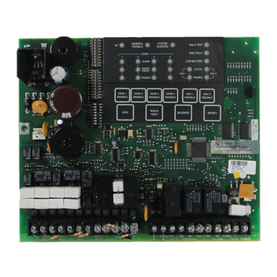
Page 9: Sk-4224 Board Layout
Before You Begin Installing SK-4224 Board Layout Figure 3-1 shows the SK-4224 circuit board including location of terminals, connectors, dip switches, and LEDs. Annunciator Programming DIP Switches SK-2884 AC Power Connector Serial Interface Connector On-Board Piezo Sounder Backup Battery Connector... -
Page 10: Electrical Specifications
32° - 120° F (0° - 49 ° C) Humidity: 10 - 85% non-condensing It is important to protect the SK-4224 control panel from water. To prevent water damage, the following conditions should be AVOIDED when mounting the units: •... -
Page 11: Mounting The Sk-4224
Before You Begin Installing Mounting the SK-4224 Read the environmental specifications in Section 3.5 before mounting the cabinet. The panel should be accessible to main drop wiring runs. It should be mounted as close to the center of the building as possible and located within a secured area, but should be accessible for testing and service. -
Page 12: Assembly
1. Remove keys from small manila envelope taped to the top of the cabinet. 2. Unlock the cabinet door. 3. Remove the packing material and the SK-4224 components. 4. Snap the bezel into the opening in the front of the cabinet. See Figure 3-3. -
Page 13: Wiring Specifications
Before You Begin Installing Wiring Specifications Induced noise (transfer of electrical energy from one wire to another) can cause false alarms or interfere with control panel operation in other ways. To avoid induced noise, follow these guidelines: • Isolate input wiring from high current output and power wiring. Do not pull one multi- conductor cable for the entire panel. -
Page 14: Calculating Current Draw And Standby Battery
Filling in the Current Draw Worksheet, Table 3-6 (Section 3.9.3) 1. For the SK-4224, the worst case current draw is listed for the panel and is recorded in the table at Line A. 2. Add up the current draw for all smoke detectors and record in the table at Line B. -
Page 15: Current Draw Worksheet
For each device, use this formula: This Column X This column Current per number of devices Standby: 125 mA 125 mA SK-4224 Panel Alarm: 250 mA 250 mA Current Subtotals: 125 mA 250 mA Refer to device manual for current ratings. See Appendix to this manual for Smoke Detectors max. - Page 16 Model SK-4224 Fire Control Panel Installation/Operation Manual 3-10 151068...
-
Page 17: Hardware Installation
Section 4 Hardware Installation AC Power At installation, connect the transformer AC inputs to the AC power source as shown in Figure 4-1. It may be necessary for a professional electrician to make this connection. The AC inputs are rated as 120 VAC, 60 Hz (for transformer P/N 115061) or 230 VAC,50 Hz (for transformer P/N 115031). -
Page 18: Battery Connection
Model SK-4224 Fire Control Panel Installation/Operation Manual Battery Connection The SK-4224 battery charge capacity is 7.0 AH. Use two 12V batteries of the same AH rating. Determine the correct AH rating as per your current load calculation (see Table 3-6). -
Page 19: Initiation Circuit Installation
Silent Knight's SLK-24F with HSB-224 base as an example. You can use any detector that has been UL listed for compatibility with the SK-4224. Refer to the Appendix for a list of compatible devices. Refer to Section 6 for configuration options. -
Page 20: Class A Smoke Detector Installation
4.3.3 Class A Smoke Detector Installation Figure 4-5 illustrates how to connect a UL listed smoke detector to the SK-4224 in a Class A configuration. Refer to the Appendix for a list of compatible devices. Information on selecting zone configuration options is in Section 6. -
Page 21: Four-Wire Smoke Detector
4.3.4 Four-Wire Smoke Detector Figure 4-6 shows how to connect four-wire smoke detectors to the SK-4224 loops. The figure uses Silent Knight's SLK-24F with HSC-4R base as an example. You can use any UL listed device. Refer to the Appendix for a list of compatible devices. Information on selecting zone configuration options is in Section 6. -
Page 22: Notification Circuit Installation
Notification Circuit Installation Notification appliances used with the SK-4224 must be UL listed for compatibility with the SK-4224. Refer to the list in the Appendix at the end of this manual for a list of compatible devices. For proper operation, you must use polarized notification devices with a model 7628 4.7k ohm end-of-line (EOL) resistor on each loop. -
Page 23: Class A Notification Circuit Installation
Each relay has three terminals (N.O., Common, and N.C.). Refer to Figure 3-1 for location of these terminals. Auxiliary Power Circuit The SK-4224 has a power limited auxiliary power circuit which can source up to .5A. The terminal is labeled “AUX PWR”. Refer to Figure 3-1 for location of this terminal. 151068... -
Page 24: Door Release Wiring
Model SK-4224 Fire Control Panel Installation/Operation Manual Door Release Wiring Figure 4-9 shows how to configure a door release using an ESL DH series door holder. Figure 4-9 Door Release Wiring 151068... -
Page 25: Optional Accessories Installation
2. Unplug the backup battery connector from the SK-4224 control panel. See Figure 4-2. 3. Plug the SK-2884 Serial board on SK-4224 control panel by aligning the 4-pin connector and the three stand-offs with their respective receptors. See Figure 4-10. -
Page 26: Wiring The Sk-2884 To An Expansion Device
Model SK-4224 Fire Control Panel Installation/Operation Manual Wiring the SK-2884 to an Expansion Device The SK-2884 uses a three wire connection to all of the SK-4224 compatible expansion devices (see Table 3-2). Connect all the expansion devices to the SK-2884 as follows:... - Page 27 Hardware Installation 3. Terminate the wiring as shown in Figure 4-11. See also Table 4-2. SK-2884 SK-2865 Supervised Power Limited Figure 4-11 SK-2865 Connection to the SK-2884 Table 4-2: SK-2865 Wiring Connections SK-2865 SK-2884 Terminals Terminals D (Data) D (Data) 151068 4-11...
-
Page 28: Setting The Sk-2865'S Address
Model SK-4224 Fire Control Panel Installation/Operation Manual Setting the SK-2865’s address The range of valid addresses is 0-3. Each device requires a unique address. Set the dip switches as shown in Table 4-3. See also Figure 4-11. Table 4-3: SK-2865 Addresses Per Dip Switch Setting... - Page 29 Hardware Installation 4.7.3 SK-2880 Installation The SK-2880 is an Input/Output module. The SK-2880 has 33 pre-defined open collector outputs (see Table 4-6) that can be used to drive LEDs, interface with other controls or systems, or control one of the three built-in Form C relays. See Figure 4-13, Figure 4-15 and Figure 4-16.
- Page 30 Model SK-4224 Fire Control Panel Installation/Operation Manual 4.7.3.1 Connecting the SK-2880 to the SK-2884 The control panel communicates to the I/O module through the Serial Interface Board (see also Section 4.7.1). Figure 4-14 illustrates how to properly wire the I/O module to the Serial Interface Board.
- Page 31 Hardware Installation 4.7.3.3 Open Collector Outputs (P1, P2, and P3) Each pin on the Pin Connectors (P1, P2, and P3) have a predefined output. Table 4-6 lists the Pin Connectors and describes what each pin outputs. Table 4-6: Pin-outs for Open Collector Outputs Pin Number Output Description...
- Page 32 Model SK-4224 Fire Control Panel Installation/Operation Manual Table 4-6: Pin-outs for Open Collector Outputs Pin Number Output Description Connector Pin 1 NAC 1 Trouble Outputs when a trouble condition exists on NAC 1. Pin 2 NAC 2 Trouble Outputs when a trouble condition exists on NAC 2.
- Page 33 Hardware Installation 4.7.3.4 SK-2880 Input Switches and Relay Wiring This section describes the components of terminal strip 2 (see Figure 4-13) on the SK-2880. Terminal strip 2 provides two input switches (Reset & Silence) and three Form C relay. Figure 4-16 illustrates how to configure the inputs switches and the Form C Relays.
- Page 34 Model SK-4224 Fire Control Panel Installation/Operation Manual 4.7.3.5 Mounting the SK-2880 The I/O module must be mounted in a UL Listed enclosure. Follow these steps to mount the SK-2880: 1. Remove the SK-2880’s cover. A small screw driver can be used.
-
Page 35: Notification Expansion Mode
FACP input of the SK-4224, which can trigger the SK-4224 notification cicuits when the host panel goes into alarm. Note: The SK-4224 does not go into the alarm state when the host control panel triggers the SK-4224’s notification cicuits. -
Page 36: Class B Notification Expansion Wiring
Figure 5-2 shows Class B supervised wiring from a host fire alarm control panel to the SK- 4224 control panel. Use an EOL resistor as shown in to supervise the FACP input. The host fire alarm control panel may use an EOL with a value other than 4.7 KΩ, used by the SK- 4224. -
Page 37: System Configuration
Section 6 System Configuration To configure the SK-4224 system set the dipswitch that controls the option you want to select. The following chart shows how to program the dipswitches that control system, zone, and notification appliance operation. Refer to Figure 3-1 for location of the dipswitches. - Page 38 Model SK-4224 Fire Control Panel Installation/Operation Manual Table 6-1: System Configuration To Enable For Entire Panel (DIP 3) DIP Position ON = Serial Annunciator connected to the control panel. OFF = No Serial Annunciator connected to the control panel. Serial Accessory Devices...
-
Page 39: System Operation
Section 7 System Operation The annunciator on the SK-4224 board is used for all system operation. It contains the switches for enabling silencing, resetting, and so on. The LEDs that indicate system status are also located on the annunciator. Figure 7-1 On-Board Annunciator Meaning of LEDs The chart below explains the meaning of LEDs on the system board. - Page 40 Model SK-4224 Fire Control Panel Installation/Operation Manual Table 7-1: Meaning of LEDs LED (Color) Function Comments GND FAULT (yellow) ON = Ground fault condition exists and was acknowledged If flashing press the ACK button to acknowledged the condition. OFF = No fault...
-
Page 41: Operation Keys (Switches)
System Operation Operation Keys (Switches) All system operation are performed from the on-board keys (switches) as described in the chart below. Table 7-2: Operations and Instructions Operation Keystrokes Disable notification appliance Press the appropriate [NAC DISABLE] key. The NAC circuit will be disabled and circuit. - Page 42 Model SK-4224 Fire Control Panel Installation/Operation Manual 151068...
-
Page 43: Appendix A Compatible Devices
Compatible Devices This section of the manual lists devices (smoke detectors and notification appliances) that are compatible with the SK-4224. Contact Silent Knight if you have a question about whether a device not listed here is compatible. A.1 Smoke Detectors This section of the manual contains information about smoke detectors that are compatible with the SK-4224. -
Page 44: A.1.2 Two-Wire Smoke Detectors
Model SK-4224 Fire Control Panel Installation/Operation Manual A.1.2 Two-Wire Smoke Detectors The table below lists two-wire smoke detectors that are compatible with the SK-4224. The table is organized by manufacturer. The columns show the number of detectors per loop that can be used. -
Page 45: Four-Wire Smoke Detectors
2451DH (DH 400) 20 / loop 2451TH (B401B) 20 / loop Four-Wire Smoke Detectors Table A-2: Compatible Four-Wire Smoke Detectors Manufacturer Model Silent Knight SD-P24F with SD-B4@ base Detection Systems DS200/DS200HD MB200 445 Series 449 Series Gentex 2040-24 Power Supervision Unit... -
Page 46: A.2 Notification Appliances
Model SK-4224 Fire Control Panel Installation/Operation Manual A.2 Notification Appliances The chart below lists notification appliances compatible with the SK-4224. Note: Units that operate at 12 or 24 VDC must be selected for 24 VDC operation. Table A-3: Compatible Notification Devices... - Page 47 Compatible Devices Table A-3: Compatible Notification Devices Manufacturer Model Type Faraday 5522B-( )-14-24-DC 4” Square Sync Strobe (flush) Faraday 6126B-U-14-24 VDC Horn/Strobe Faraday 6223B-0-14-24-DC Horn (flush) Faraday 6224B-0-14-24-DC Horn (surface) Faraday 6225B-0-4-24-DC Horn (ceiling) Faraday 6226B-( )-14-24-DC Horn/Strobe (flush) Faraday 6227B-( )-14-24-DC Horn/Strobe (surface) Faraday...
- Page 48 Model SK-4224 Fire Control Panel Installation/Operation Manual Table A-3: Compatible Notification Devices Manufacturer Model Type Gentex SHG24-15 Horn/Strobe Gentex GMH-24-X Horn Gentex GMS-24-X Horn/Strobe Gentex GMS-24-X Horn/Strobe Gentex G0T24 Horn Gentex G0S24-X Horn Gentex WGMS-24-X Horn/Strobe System Sensor MASS241 Horn/Strobe...
- Page 49 Compatible Devices Table A-3: Compatible Notification Devices Manufacturer Model Type Wheelock AES-EL1-WH-24-VF-R Multitone Horn Wheelock AES-DL1-WM-24-VF-R Multitone Horn Wheelock AES-EL1-WM-24-VF-R Multitone Horn Wheelock AH-24-R Horn Wheelock AH-24WP-R Horn Wheelock AMT-12\24-R Strobe Horn Wheelock AMT-24-LS-VFR Strobe Horn Wheelock AMT-24-LSM-VFR Strobe Horn Wheelock AMT-24-IS-VFR Strobe Horn...
- Page 50 Model SK-4224 Fire Control Panel Installation/Operation Manual Table A-3: Compatible Notification Devices Manufacturer Model Type Wheelock CH70-2475W-FR Chime Strobe Wheelock CH70-24110W-FR Chime Strobe Wheelock CH-CF1 Chime Wheelock CH-CF1-R Chime Wheelock CH-CF1-W Chime Wheelock CH-DF1 Chime Wheelock CH-DF1-R Chime Wheelock CH-BF1-WS-24-HF-R...
- Page 51 Compatible Devices Table A-3: Compatible Notification Devices Manufacturer Model Type Wheelock EH-EL1-WH-24-VF-R Strobe Horn (dual input) Wheelock EH-DL1-WM-24-VF-R Strobe Horn (dual input) Wheelock EH-EL1-WM-24-VF-R Strobe Horn (dual input) Wheelock HSW-24-HFR Remote Strobe Wheelock HS2W-24-HFR Remote Strobe Wheelock HSPW-24-HFR Remote Strobe Wheelock IS-24-VFR Remote Strobe...
- Page 52 Model SK-4224 Fire Control Panel Installation/Operation Manual Table A-3: Compatible Notification Devices Manufacturer Model Type Wheelock MIZ-24-IS-VFR Mini-Horn/Strobe Wheelock MIZ-24-WS-VF-R Mini-Horn/Strobe Wheelock MIZ-24-WS-VF-W Mini-Horn/Strobe Wheelock MIZ-24-WH-VF-W Mini-Horn/Strobe Wheelock MIZ-24-WM-VF-W Mini-Horn/Strobe Wheelock MT-12/24-R Strobe Horn Wheelock MT4-12/24-R Multitone Appliance Wheelock MT4-115-R...
- Page 53 Compatible Devices Table A-3: Compatible Notification Devices Manufacturer Model Type Wheelock RSP-2415-VFR Strobe Wheelock RS-241575-VFR Strobe Wheelock RSP-241575-VFR Strobe Wheelock RS-2430-VFR Strobe Wheelock RS-2430-HFR Strobe Wheelock RS-2475-VFR Strobe Wheelock RSP-2475-HFR Strobe Wheelock RS-24110-HFR Strobe Wheelock RSP-24110-HFR Strobe Wheelock RSS-2415W-FR Strobe Wheelock RSS-241575W-FR Strobe...
- Page 54 Model SK-4224 Fire Control Panel Installation/Operation Manual Table A-3: Compatible Notification Devices Manufacturer Model Type Wheelock SH2W-24-VFR Synchronized Remote Strobe Wheelock SHPW-24-VFR Synchronized Remote Strobe Wheelock SCM-24-R Controller for Synchronized Strobes Wheelock SM-12/24-R Sync Module Wheelock SR-2415-VFR Sync Strobe Wheelock...
- Page 55 Repair and RA Procedure • All products that are returned to Silent Knight for credit or repair require a RA (Return Authorization) number. Call Silent Knight Customer Service at 800-446-6444 or 612-493- 6435 between 8:00 A.M. and 5:00 P.M. CST, Monday through Friday to obtain a return authorization number.
- Page 56 RA Number:___________________ Limited Warranty Silent Knight warrants that the products of its manufacture shall be free from defects in materials or workmanship for 18 months from the manufacturing date code on the printed circuit board, if such goods have been properly installed, are subject to normal proper use, and have not been modified in any manner whatsoever.
- Page 57 SK-4224 BasicOperating Instructions P/N 151066 These instructions must be framed and displayed next to the SK-4224 panel in accordance with NFPA 72 fire code for Local Fire Alarm System. LED (Color) Function Comments AC (green) ON = Good AC If flashing press the ACK button to acknowledged the condition.
- Page 58 Cut Along the Dotted Line...
Need help?
Do you have a question about the 4224 and is the answer not in the manual?
Questions and answers