
Subscribe to Our Youtube Channel
Related Manuals for Snorkel TB66JRT


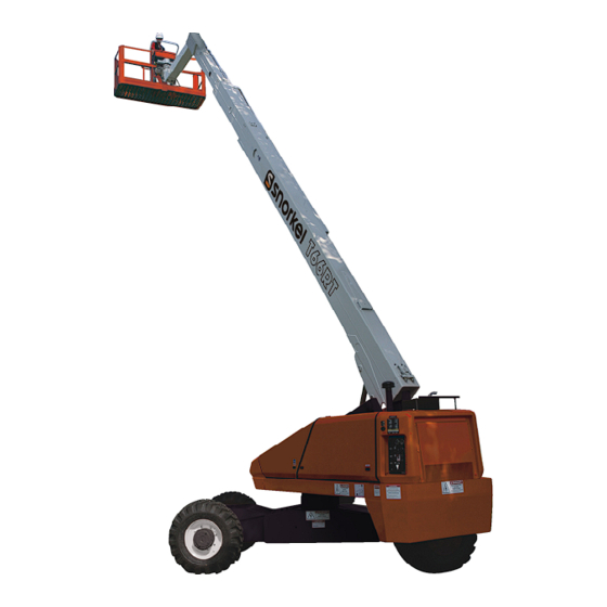
Summary of Contents for Snorkel TB66JRT
- Page 1 OPERATOR’S MANUAL Part Number 0083740 May 2014 Models TB66J/TB66JRT Replaces 0083740 March 2014...
- Page 2 The aerial platform is not electrically insulated. Death or serious injury will result from contact with, or inadequate clearance from, an energized conductor. Do not go closer than the minimum safe approach distance as defined by the Minimum Safe Approach Distance section in Chapter 3 – Safety. Regard all conductors as energized.
-
Page 3: Table Of Contents
Table of Contents Chapter 5 – Gauges and Displays Electrical Danger ......Inside Front Cover Hour Meter..............19 California Proposition 65 ....Inside Front Cover Engine Temperature Gauge ........19 Chapter 1 – Introduction Ammeter – Cummins, Deutz and Ford Engines ..19 Voltmeter –... - Page 4 Table of Contents Chapter 7 – Prestart Inspection Chapter 8 – Operation Operator’s Manual ..........29 Cold Weather Start Up ...........49 Engine ..............29 Engine Cold Weather Start Kit ........49 Oil Level ..............29 Cummins, Kubota and Ford – Block Heater ..49 Coolant ..............29 Cummins –...
-
Page 5: Chapter 1 - Introduction
General Motors 2.4L – Gasoline, LPG or dual fuel Additional copies of this manual may be ordered from Snorkel. Supply the model and manual part number The aerial platform has been manufactured to conform from the front cover to assure that the correct manual to all applicable requirement of the following organiza- will be supplied. -
Page 6: Operation
Read and understand sees of ANSI/SIA A92.5-2006 Boom-Supported Elevat- the information in this manual and on the placards ing Work Platforms” is available from Snorkel dealers or and decals on the machine before operating the from the factory upon request. -
Page 7: Chapter 3 - Specifications
Chapter 3 – Specifications Component Identification Operator’s Manual Wiring Box Fuel Tank Lower Controls Upper Controls LP Fuel Tank Steer Wheels Chassis Right Side Emergency Intermediate Main Boom Lowering Boom Hydraulic Fluid Tank Tip Boom Valve And Filter Battery Disconnect Switch Engine Platform Batteries... -
Page 8: Working Envelope
Chapter 2 – Specifications Working Envelope Feet (Meters) (21.3) (18.3) (15.2) (12.2) (9.1) (6.1) (1.5) (18.3) (15.2) (12.2) (9.1) (6.1) TB66J – 0083740... -
Page 9: General Specifications
Chapter 2 – Specifications General Specifications Aerial Platform Drive System Working height 72′ (21.9 m) Standard Four-wheel drive Maximum platform height 66′ (20.1 m) Gradeability Horizontal reach 56′ (17.1 m) Optional Two-wheel drive Main boom Gradeability Articulation -1° to +72° Extension 0 to 27′... -
Page 10: Engine Specifications
Chapter 2 – Specifications Engine Specifications Operating Engine Displacement Fuel Grade Coolant Temperature Capacity Grade Diesel ASTM No. 2D fuel with a mini- 15W-40 Cummins 199 cu. in. 50% Water 140°F to 212°F 2 US gal mum Cetane no. of 40. For op- B3.3 (3.26 liter) - Page 11 Chapter 2 – Specifications Operating Engine Displacement Fuel Grade Coolant Temperature Capacity Grade Gasoline Unleaded 87 or 89 octane. Do not use gasoline blends with more than 10% ethanol by Ford 153 cu. in. 50% Water 195°F to 220°F 4.5 US qt API: SH volume octane index of 87 or 89.
-
Page 12: Engine Oil Viscosity
Chapter 2 – Specifications Engine Oil Viscosity Cummins B3.3 Deutz F4L-1011F Deutz F4L-2011F Kubota V2403-M-T S A E 15W /40 TB66J – 0083740... - Page 13 Chapter 2 – Specifications Ford LRG 423 Ford LRG 425 General Motors 2.4L °F -4 0 -3 1 -2 2 -1 3 -4 14 23 32 41 50 59 68 77 86 10 4 12 2 °F °C -4 0 -3 5 -3 0 -2 5 -2 0 -1 5 -1 0 -5 10 15 20 2 5 30 40 50 °C S A E 5W /30...
- Page 14 Chapter 2 – Specifications TB66J – 0083740...
-
Page 15: Chapter 3 - Safety
Chapter 3 – Safety Minimum Safe Approach Distance Knowledge of the information in this manual, and proper training, provide a basis for safely operating the Minimum safe approach distances to energized power aerial platform. Know the location of all controls and lines and their associated parts must be observed while how they operate to act quickly and responsibly in an operating the aerial platform. -
Page 16: Prestart Inspection
Chapter 3 – Safety Prestart Inspection booms, or platform. Allow sufficient room and time to stop movement to avoid contact with structures Perform a prestart inspection before each shift as de- or other hazards. scribed in Chapter 7. Do not use the aerial platform on the job unless you are trained and authorized to do so. -
Page 17: Tip-Over And Falling Hazards
The hydraulic system contains hoses with hydraulic fluid loads that extend beyond the platform guardrails without under pressure. prior written consent from Snorkel. Danger Do not operate the aerial platform from trucks, trail- Hydraulic fluid escaping under pressure can have ers, railway cars, floating vessels, scaffolds or similar enough force to inject fluid into the flesh. -
Page 18: Engine And Fuel Handling Precautions
Tighten the fuel tank cap securely. If the fuel cap is lost, maintenance and specifications. replace it with an approved cap from Snorkel. Use of a non-approved cap without proper venting may result in Danger pressurization of the tank. -
Page 19: Chapter 4 - Safety Devices
Chapter 4 – Safety Devices This aerial work platform is manufactured with safety On older machines the emergency stop is a two- position toggle switch with a red safety guard. devices, placards, and decals to reduce the likelihood of an accident. Push the guard down over the toggle switch to dis- ... -
Page 20: Emergency Lowering Knob
Chapter 4 – Safety Devices Emergency Lowering Knob Guardrails The emergency lowering knob may be used to lower The guardrails (refer to Figure 4.5) help protect person- the booms if the engine will not start and the emergency nel from falling off the platform. power system will not work. -
Page 21: Ground Fault Circuit Interrupter
Chapter 4 – Safety Devices Ground Fault Circuit Interrupter The electrical power outlet at the platform (refer to Figure Engine 4.6) contains a ground fault circuit interrupter (GFCI) to provide protection for personnel. Temperature Gauge Electrical Power Outlet Figure 4.6 – Electrical Outlet Tilt Alarm If the aerial platform chassis is out of level more than five degrees when the main boom is raised or extended,... -
Page 22: Horn
Chapter 4 – Safety Devices Horn Driving Lights An optional horn may be used to warn personnel on The optional headlights and blinking tail lights may be the ground. The horn button is on the right side of the used to help improve visibility while driving the aerial upper control box. -
Page 23: Chapter 5 - Gauges And Displays
Chapter 5 – Gauges and Displays The aerial platform is equipped with several gauges to Ammeter – Cummins, Deutz and Ford monitor the condition of the machine before and during Engines operation. The ammeter is located on the lower control panel (refer to Figure 5.2). -
Page 24: Engine Oil
Chapter 5 – Gauges and Displays Hydraulic Fluid Filter Gauge The fluid filter gauge (refer to Figure 5.6) is located on the return line filter on the top of the reservoir. The reservoir is behind the door on the left side of the turntable. Fuel Gauge During high pump flow situations, the gauge indi- ... -
Page 25: Chapter 6 - Controls
Chapter 6 – Controls The following are located on the lower control panel. Danger Pinch points may exist between moving compo- • Emergency stop button nents. Death or serious injury can result from being • Control selector switch trapped between components, buildings, structures, •... -
Page 26: Ground Operation Switch
Chapter 6 – Controls Boom Elevation Switch Control Selector Switch Boom Speed Boom Extend/Retract Knob Switch Emergency Stop Button Platform Rotation Engine/Emergency Switch Power Switch Ground Operation Platform Level Switch Switch Rotation Switch Start Switch Throttle Switch Circuit Breaker Reset Button Jib Articulation Switch Figure 6.2 –... -
Page 27: Boom Speed Knob
Chapter 6 – Controls Boom Speed Knob If the engine is running, it will stop when the switch is The boom speed knob (refer to Figure 6.2) is used to placed in the emergency power position. control the speed of the following boom functions: Throttle Switch Main boom raise/lower The throttle switch (refer to Figure 6.2) is used to set the... -
Page 28: Circuit Breaker Reset Buttons
Chapter 6 – Controls Note Machine functions are not operational while using the hydraulic warm-up system. To warm-up the hydraulic fluid from the lower controls: 1. Start the engine from the lower controls. Circuit Breaker Reset Buttons 2. Place the hydraulic fluid warm-up switch in the on position. -
Page 29: Start Switch
Chapter 6 – Controls The following controls are located on the upper control Note panel. On some machines it may be necessary to pause about three seconds in the on position before going to start so • Start switch the starter can engage. •... -
Page 30: Drive Range Switch
Chapter 6 – Controls Note Jib Articulation Switch The distance the joystick is moved is proportional to the The jib switch (refer to Figure 6.6) is used to raise or lower the jib. The switch is spring returned to the center speed of the function. -
Page 31: Engine/Emergency Power Switch
Chapter 6 – Controls quieter and the engine will consume less fuel than at high throttle operation. High engine speed is obtained when the main boom is horizontal, the foot switch is depressed, the throttle switch is in the high position, and the drive joystick is moved out of neutral into the forward or reverse Platform Foot position. -
Page 32: Driving And Platform Work Lights
Chapter 6 – Controls Driving and Platform Work Lights Caution The control for the optional driving lights is on the back Not all hydraulic fluid is suitable to use in the hy- of each light. Place the switch in the on position to oper- draulic system. -
Page 33: Chapter 7 - Prestart Inspection
Chapter 7 – Prestart Inspection Engine Potential service and safety problems may be detected by inspecting the aerial platform. This chapter includes Visually inspect the engine and its components with the information on properly inspecting the aerial platform engine off. The engine is located behind the doors at the and includes a prestart inspection check list at the end front of the machine (refer to Figure 7.2). -
Page 34: Radiator
Chapter 7 – Prestart Inspection When the engine is cold, there should be about 1″ 2. Make sure the hoses are not hardened, cracked, or (2.5 cm) of coolant in the bottom of the reservoir. feel spongy. When the engine is at operating temperature, the 3. -
Page 35: Fuel Line
Chapter 7 – Prestart Inspection Air Filter Gauge Reset Button Shutoff Valve Engine Temperature Gauge Ammeter – Cummins, Deutz, Quick Disconnect Fitting and Ford Engines Voltmeter – General Motors Engines Slot Figure 7.5 – LPG Tank Figure 7.6 – Gauges at Lower Controls To inspect the air filter: 2. -
Page 36: Electrical System
Chapter 7 – Prestart Inspection Electrical System 3. If necessary, add distilled water. Electrical power is supplied from either one or two, 550 Note CCA, 12 volt batteries (refer to figure 7.7). These bat- Use only distilled water when refilling the battery. Tap teries supply 12 volt DC electrical power to operate the water may contain metallic solids such as iron which aerial platform electrical and electrohydraulic compo-... -
Page 37: Fluid Filter
Chapter 7 – Prestart Inspection 2. Open the door on the right side of the chassis to ac- cess the hydraulic fluid level gauge (refer to Figure 7.8). Full Figure 7.9 – Hoses, Tubes, and Fittings 2. Make sure the hoses are properly routed to avoid sharp edges, kinking, and scuffing. -
Page 38: Lower Control Station
Chapter 7 – Prestart Inspection 2. Carefully inspect for large holes or cuts where foam Danger is coming out of the tire. Pinch points may exist between moving components. Death or serious injury will result from becoming 3. Look for large imbedded objects, such as angle iron, trapped between components, buildings, structures, that can rip a tire open. -
Page 39: Level Sensor
Chapter 7 – Prestart Inspection Danger Pinch points may exist between moving components. Death or serious injury will result from becoming trapped between components. Make sure all person- nel stand clear while lowering the platform with the emergency lowering knob. Level Sensor 3. -
Page 40: Sandblast Protection Kit
Chapter 7 – Prestart Inspection Note Slide Pads There is not an off switch for the flashing light. The light The main boom has slide pads (refer to Figure 7.16) between the boom sections. cannot be turned off. Sandblast Protection Kit The optional sandblast protection kit protects the cyl- inders from abrasion while sandblasting or from paint overspray. -
Page 41: Fasteners
Chapter 7 – Prestart Inspection Rotation Bearing Bolts Figure 7.18 – Top of Main Boom at Base End Figure 7.20 – Inside Turntable Also inspect the wire ropes just inside the base end of 4. Inspect the inner and outer race rotation bearing the main boom (refer to Figure 7.19). -
Page 42: Lanyard Anchors
Chapter 7 – Prestart Inspection 3. Visually inspect all bolts and nuts fastening the or other obstacles. Make sure all personnel stand platform in place. They must be present and not clear of the aerial platform while performing the show any signs of looseness. prestart inspection. -
Page 43: Horn
Chapter 7 – Prestart Inspection 4. Hold the engine/emergency power switch in the Plug an electrical tool into the receptacle at the platform emergency power position and step on the platform and try to operate the tool to verify proper operation of foot switch to verify operation of the aerial platform the outlet. -
Page 44: Tow Kit
Keeper Pins 4. Replace any missing, damaged, or illegible placards or decals before operating the aerial platform. Placard and decal kits are available from Snorkel. Trays The safety related placards and decals are illustrated Figure 7.26 – Platform on the following pages. - Page 45 Chapter 7 – Prestart Inspection 0074311 (One per Cylinder) 0070901 0073491 0074311 Snorkel International 1-800-255-0317 2009 Roseport Road Elwood, KS 66024 M O D E L S E R IA L N U M B E R N U M B E R...
- Page 46 Chapter 7 – Prestart Inspection 0074210 MACHINE TIPOVER HAZARD DEATH or serious injury can result if machine tips over. 0081441 This machine is equipped with foam filled or solid tires, wheel weight is critical for stability. (Dual Fuel or LPG Only To prevent machine tip over, replace tires with factory approved Inside Door) foam filled or solid tires ONLY.
- Page 47 Chapter 7 – Prestart Inspection 0323897 DANGER 0082203 0082164 (Tow Option Only) (Tow Option Only) DO NOT RIDE IN PLATFORM WHILE UNIT IS BEING TOWED. 0082164 0082164 0323897 0082160 A “RUNAWAY” SNORKELIFT CAN CAUSE DEATH OR SERIOUS INJURY. CHECK (Tow Option Only) WITH TOW VEHICLE MANUFACTURER OR MANUFACTURER'S LITERATURE TO SEE THAT TOW VEHICLE CAN SAFELY TOW AND STOP TOTAL WEIGHT OF SNORKELIFT ON THE STEEPEST GRADE YOU WILL ENCOUNTER.
- Page 48 Chapter 7 – Prestart Inspection 0323896 0074316 0323899 (Ford Engine Only Inside Door) 0323896 0073298 0073298 Left Side Turning battery disconnect switch off while engine is running will damage engine governor. 0074316 0074316 0323896 Front Allow for sway, rock, and sag. 0323899 TB66J –...
- Page 49 Chapter 7 – Prestart Inspection 0072531 0072531 Platform 0072530 0072530 Upper Control Panel Front 0151410 0151410 DANGER FA L L IN G O B JE C T H A Z A R D D E AT H o r serio u s in ju ry can resu lt fro m lo ss o f co n tro l o f carried m aterial.
- Page 50 Chapter 7 – Prestart Inspection TB66J – 0083740...
-
Page 51: Prestart Inspection Checklist
Chapter 7 – Prestart Inspection Prestart Inspection Checklist Item Inspect For Operator’s Manual In place, all pages readable and intact Engine Oil Level Between full and add marks Coolant Liquid cooled engines – proper fluid level Air cooled engines – air intake and fan free of obstructions, belt in good condition Radiator Cap tight, good condition and clean... - Page 52 Chapter 7 – Prestart Inspection TB66J – 0083740...
-
Page 53: Chapter 8 - Operation
Chapter 8 – Operation The aerial platform may be operated from either the Cold, thick hydraulic oil does not flow well and may cause delay in response to control movement and lower or upper controls. improper voltage output of the optional AC generator. Cold hydraulic oil may also cause cavitation and pump Danger damage. -
Page 54: Deutz - Manifold Preheater
Chapter 8 – Operation 5. Place the battery disconnect switch in the on posi- gine was started. For example, if the engine was started tion. from the lower controls, the warm-up switch at the lower controls must be used for the system to operate. Activate the toggle switch while the start switch is in the start position to inject a measured amount of ether into To operate the warm-up system:... -
Page 55: Upper Controls
Chapter 8 – Operation Use the following procedure to operate boom, turntable, 7. Hold the appropriate toggle switch in the desired or platform functions using the lower controls. Refer to direction. Figure 8.2. 8. Gradually turn the boom speed knob to control the 1. -
Page 56: Boom Operation
Chapter 8 – Operation Emergency Stop Button Start Switch Front Figure 8.4 – Upper Controls 7. Turn the start switch to on and pause a few sec- Driving and Steering onds while the alarm sounds to alert others that the machine is about to start. -
Page 57: Drive Speeds
Chapter 8 – Operation The blue and yellow arrows on the chassis indicate the • Push the drive joystick to the left to steer to the direction the chassis will move when the drive or steer left, the direction of the blue arrow. control is moved toward the corresponding color. -
Page 58: Percent Vs. Degree Of Slope
Chapter 8 – Operation Percent vs. Degree of Slope Drive the aerial platform only on slopes, or loading Gradeability is most often referenced as a percentage. ramps that are within the 20 percent grade capability of That value is based on a slope angle of 45° represent- the aerial platform. -
Page 59: Machine Gradeability
Chapter 8 – Operation The grade can be measured with an inclinometer or by Four wheel drive machines have a “4x4” decal on each using a tape measure, a level, and a straight 2 x 4. If side of the chassis and all four of the wheel hubs are using an inclinometer, refer to the conversion diagram drive hubs and look the same. -
Page 60: Dual Fuel
• The maximum working pressure of the line is 250 psi (1,723 kPa). The air line may be used to conduct fluids such as water or antifreeze. Contact Snorkel for compatibility informa- tion before using the air line to conduct other fluids. TB66J – 0083740... -
Page 61: Platform Glazier Package
The glazier package allows the platform operator to eration. position glass at the work place. Refer to the Glazier Package manual (Snorkel Part Number 0421269) for information on proper use of the glazier package. The package includes two lined trays with keeper pins, platform rail padding, and tie-down straps with protectors (refer to Figure 8.11). - Page 62 Chapter 8 – Operation TB66J – 0083740...
-
Page 63: Chapter 9 - Stowing And Transporting
Chapter 9 – Stowing and Transporting To prevent unauthorized use and damage, properly stow Danger the aerial platform at the end of each work day. It must The aerial platform can tip over if it becomes un- also be properly stowed while transporting. stable. -
Page 64: Winching
Chapter 9 – Stowing and Transporting 5. Rotate the platform so it is perpendicular to the boom. 6. Retract the tip boom. Raise the main boom and jib so they are horizontal. 7. Rotate the turntable slightly to the side so you can see the front wheels. -
Page 65: Securing For Transport
Chapter 9 – Stowing and Transporting 3. Remove all personnel, tools, materials, or other Warning loose objects from the platform. The potential for an accident increases when the aerial platform is lifted using improper equipment and/or 4. Connect the chains or straps to the lifting lugs using lifting techniques. - Page 66 Chapter 9 – Stowing and Transporting 3. Raise the main boom about 1′ (0.3 m). 10. Use wire-ties to fasten the platform gate to the guardrails to prevent the gate from bouncing. Also, 4. Place a wood block under the rotator pylon. Lower use wire-ties to fasten the platform foot switch to the boom so the pylon rests on the wood block.
-
Page 67: Chapter 10 - Emergency Operation
Chapter 10 – Emergency Operation If the main hydraulic system fails, the aerial platform may be lowered and stowed using the emergency power system. The main boom may be lowered using the emergency lowering knob. The machine may be towed at slow speeds using the optional tow kit if the Control Selector drive system fails. -
Page 68: Emergency Lowering
Chapter 10 – Emergency Operation Emergency Engine/Emergency Stop Button Power Switch Start Switch Front Figure 10.3 – Upper Controls 3. Step down on the platform foot switch (refer to Figure Use the following procedure to manually lower the main 10.4). boom. -
Page 69: Towing
Chapter 10 – Emergency Operation Towing The aerial platform may be towed at slow speeds using the optional tow kit. The tow vehicle must have sufficient capacity to safely tow and stop itself and the aerial plat- form on the steepest grade and type of surface that may be encountered. - Page 70 Chapter 10 – Emergency Operation TB66J – 0083740...
-
Page 71: Chapter 11 - Troubleshooting
Chapter 11 – Troubleshooting action listed, stow the machine and remove it from ser- The troubleshooting chart may be used to locate and eliminate situations where machine operation may be vice. Repairs must be made by qualified maintenance personnel. interrupted. If the problem cannot be corrected with the Troubleshooting Chart Symptom Possible Cause... - Page 72 Chapter 11 – Troubleshooting Symptom Possible Cause Corrective Action Engine will not start from lower Switches are set wrong. The engine Turn the battery disconnect switch controls. will not crank. on and then at the lower controls: • Turn the start switch off. •...
- Page 73 Chapter 11 – Troubleshooting Symptom Possible Cause Corrective Action Engine starts from the upper con- The AC generator switch is in the Place the switch in the machine posi- trols but no boom functions work generator position. tion to operate machine functions. –...
- Page 74 Chapter 11 – Troubleshooting Symptom Possible Cause Corrective Action Boom and drive functions seem Hydraulic oil is cold and thick. Use cold weather hydraulic oil as sluggish. recommended for weather condi- tions. Warm oil before operating the machine. Boom jerks while it is extended. Wire ropes are loose.
- Page 75 Chapter 11 – Troubleshooting Fuel Line Air Bleeding – Kubota V2403-M-T If the engine will not start because of air in the fuel line, use one of the following methods to remove the air to restart the engine. Open Bleeder Valve and Crank Engine Slightly open the bleeder valve (refer to Figure 11.1) and crank the engine for a few seconds to let the air out.
- Page 76 Chapter 11 – Troubleshooting TB66J – 0083740...
-
Page 77: Appendix A - Glossary
This system includes a harness or belt, lanyard prestart inspection – a required safety inspection routine that is performed and a lanyard anchor. Federal OSHA, ANSI and Snorkel require the use daily before operating the aerial platform. - Page 78 Appendix A – Glossary TB66J – 0083740...
- Page 79 5. The Customer and Dealer shall not be entitled to the benefits of this warranty and Snorkel shall have no obligations here under unless the “Predelivery and Inspection Record” has been properly com- pleted and returned to the Snorkel Warranty department within fifteen (15) days after delivery of the Snorkel product to the Customer or Dealer’s demonstration/rental fleet.
- Page 80 Confirmation that a qualified technician is available to replace the part and that this person has been ac- cepted by Snorkel to carry out such work under the warranty of the machine. Failure to do this may nullify the warranty.
- Page 81 PURPOSE AND DISCLAIMS ALL LIABILITY FOR INCIDENTAL OR CONSEQUENTIAL DAMAGES, INCLUD- ING BUT NOT LIMITED TO INJURY TO PERSONS OR PROPERTY. The Customer shall make all warranty claims through Snorkel directly or an Authorised Distributor. If unable to contact the Distributor, contact the Snorkel Service Department for further assistance.
-
Page 82: Limited Warranty
Product Warranty APPEAL The buyer may appeal in writing against a rejected or adjusted claim to Snorkel Warranty Department within a period of 21 days of receiving the rejection or adjustment notice. The appeal should be grounded on express rea- sons and supported by relevant evidence. - Page 84 Local Distributor / Lokaler Vertiebshändler / Distributeur local El Distribuidor local / ll Distributore locale EUROPE, MIDDLE EAST AFRICA & ASIA PHONE: +44 (0) 845 1550 058 FAX: +44 (0) 845 1557 756 NORTH & SOUTH AMERICA PHONE: +1 785 989 3000 TOLL FREE: +1 800 255 0317 FAX: +1 785 989 3070 AUSTRALIA...
Need help?
Do you have a question about the TB66JRT and is the answer not in the manual?
Questions and answers