Table of Contents
Advertisement
REMOTE CONTROLLER (WIRED TYPE)
UTY-RNRYZ1
UTY-RNRGZ1
UTY-RNRXZ1
OPERATING MANUAL
WIRED REMOTE CONTROLLER
Keep this manual for future reference.
BEDIENUNGSANLEITUNG
KABEL-FERNBEDIENUNG
Bewahren Sie dieses Handbuch für eine spätere Bezugnahme auf.
MODE D'EMPLOI
TÉLÉCOMMANDE FILAIRE
Conservez ce manuel pour pour toute référence ultérieure.
MANUAL DE FUNCIONAMIENTO
MANDO A DISTANCIA CON CABLE
Conserve este manual para posibles consultas futuras.
MANUALE DI ISTRUZIONI
UNITÀ DI CONTROLLO A FILO
Conservare questo manuale per consultazione futura.
ΕΓΧΕΙΡΙΔΙΟ ΛΕΙΤΟΥΡΓΙΑΣ
ΕΝΣΥΡΜΑΤΟ ΤΗΛΕΧΕΙΡΙΣΤΗΡΙΟ
Διατηρήστε το παρόν εγχειρίδιο για μελλοντική αναφορά.
MANUAL DE FUNCIONAMENTO
CONTROLO REMOTO COM FIOS
Guarde este manual para consulta futura.
РУКОВОДСТВО ПО ЭКСПЛУАТАЦИИ
ПРОВОДНОЙ ПУЛЬТ ДИСТАНЦИОННОГО УПРАВЛЕНИЯ
Сохраните данное руководство для последующего использования.
KULLANIM KILAVUZU
KABLOLU UZAKTAN KUMANDA
Bu kılavuzu ileride başvurmak üzere saklayın.
使用产品前请仔细阅读本使用说明书
请保留本说明书以供今后参考
使用说明书
有线遥控器
[Original instructions]
PART NO. 9380859079
Advertisement
Table of Contents

Related Manuals for Fujitsu UTY-RNRYZ1


Summary of Contents for Fujitsu UTY-RNRYZ1
- Page 1 Bewahren Sie dieses Handbuch für eine spätere Bezugnahme auf. MODE D’EMPLOI TÉLÉCOMMANDE FILAIRE Conservez ce manuel pour pour toute référence ultérieure. MANUAL DE FUNCIONAMIENTO MANDO A DISTANCIA CON CABLE UTY-RNRYZ1 Conserve este manual para posibles consultas futuras. UTY-RNRGZ1 MANUALE DI ISTRUZIONI UTY-RNRXZ1 UNITÀ DI CONTROLLO A FILO Conservare questo manuale per consultazione futura.
-
Page 2: Table Of Contents
OPERATING MANUAL Initial Setting (for administrator)......17 3-8-1 Language Setting ........... 17 PART NO. 9380859079 WIRED REMOTE CONTROLLER 3-8-2 Date Setting ............17 3-8-3 Temp. Unit Setting ..........18 3-8-4 R.C.Group Name Setting ........19 Contents 3-8-5 R.C. Sensor Setting ..........19 INTRODUCTION 3-8-6 Password Setting ........... - Page 3 Screen structure Mode Air Flow Direction Setting Cool Heat Setting Setting 2-2-1 Auto Individual VT Hold Cancel Back Set Temp. Timer Setting 2-2-2 On Timer [Disable] 26.0 Off Timer [Disable] °C Auto Off Timer [Disable] Cancel Back Weekly Timer Setting 2-2-3 Enable Schedule [None]...
-
Page 4: Introduction
INTRODUCTION ■ SYSTEM OUTLINE 1 Terminology ■ SAFETY PRECAUTIONS System related terms (♦ is for VRF system) • The “SAFETY PRECAUTIONS” indicated in the manual (a) VRF system ♦: contain important information pertaining to your safety. Be VRF (Variable Refrigerant Flow) is a large multi system sure to observe them. -
Page 5: Password Configuration
2 Password configuration This unit can set the following 2 kinds of passwords: (a) Password This is a password for administrator. Password is re- quested by the setting which requires management. For a description of password setting and change, refer to [3. -
Page 6: Monitor
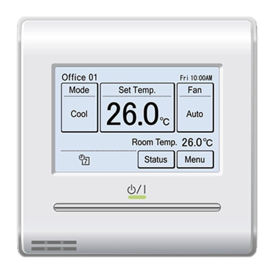
1 MONITOR It shows that it is time to clean the filter. Refer to [3 SETTING] → [3-9 Maintenance] → [3-9-3 Filter Sign Reset]. 1-1 Monitor The temperature sensor of this unit is used. Refer 1-1-1 Monitor mode screen to [3 SETTING] → [3-8 Initial Setting] → [3-8-5 R.C. Sensor Setting]. -
Page 7: Child Lock
< Error Information screen > When you try to operate or set the prohibited function, the following [Error Information] is displayed only when there is an error screen is displayed and operation history. When the [Error Information] is touched, the display Setting is prohibited. -
Page 8: Control
2 CONTROL 2-2-2 Set the Temperature (1) Touch the [Set Temp.] on the monitor mode screen. 2-1 On and Off (2) “Set Temp.” screen is displayed. Adjust the room tem- (1) Press the [On/Off] button. perature with the [ ] or [ ]. Set Temp. -
Page 9: Setting
3 SETTING 3-2-1 VT Air Flow Direction (1) Touch the [VT Setting] on the “Air Flow Direction Set- 3-1 Select the Setting Items ting” screen. (1) Touch the [Menu] on the moni- (2) “VT Air Flow Direction Setting” screen is displayed. Touch Fri 10:00AM tor mode screen. -
Page 10: Timer Setting
(3) The outlet port selection screen that sets the air flow Enable the On Timer. direction is displayed. Touch the outlet port to be set. (2) “On Timer” screen is displayed. Touch the [Enable/Dis- Check the position of each outlet port based on “ ”... -
Page 11: Auto Off Timer
Set the Operation Stop Time Set the time range of Auto Off Timer (4) Touch the [Operation Stop time] on the “Off Timer” (6) Touch the [Time Range Setting] on the “Auto Off Timer” screen. “Operation Stop Time” screen is displayed. screen. -
Page 12: Weekly Timer Setting (For Administrator)
3-4-2 Schedule Setting Apply the setting. (14) Touch the [OK] on the “Auto Off Auto Off Timer Fri 10:00AM Select the schedule to be set. Timer” screen. After the setting Enable /Disable [Enable] change screen is displayed, (1) Touch the [Schedule Setting] on the “Weekly Timer Set- Operation Stop Time [In 30 min.] the display returns to the “Timer... -
Page 13: Day Off Setting
Copy the setting of each day of the week. (8) Touch the [On/Off] on the On/Off screen of (6), and select the (12) The contents of setting per- Schedule 1 Setting Fri 10:00AM [On],[Off] or [Hold]. formed at a certain day of the Hold Wed Thu week can be copied to other... -
Page 14: Special Setting
3-5-1 Economy When setting is complete, touch the [OK]. After the set- ting complete screen is displayed, the display returns to the “Weekly Timer Setting” screen. On/Off of Economy (1) Touch the [Economy] on the “Special Setting” screen. 3-5 Special Setting (2) “Economy”... -
Page 15: Set Temp. Range Setting (For Administrator)
Apply the setting. Apply the setting. (8) Touch the [OK] on the “Set (7) Touch the [OK] on the “Set Set Temp. Auto Return Set Temp. Range Setting Temp. Auto Return” screen. Temp. Range Setting” screen. Enable /Disable [Enable] Enable /Disable [Enable] After the setting change After the setting change... -
Page 16: Fan Control For Energy Saving
3-5-6 Fan Control for Energy Saving (5) Touch the [Absence Detection Time] on the “Auto Sav- ing” screen. (for administrator) (6) The “Absence Detection Time” screen is displayed. Set (1) Touch the [Fan Control for Energy Saving] on the “Spe- the time with [ ] or [ ]. -
Page 17: Panel Calibration
3-7-2 Backlight Setting When the item to be set is touched, the display switches to each setting screen. When each setting is complete (1) Touch the [Backlight Setting] or canceled, the display returns to this screen. When Preference on the “Preference” screen. [Back] is touched, the display returns to the “Main Menu”... -
Page 18: Contrast Setting
3-7-3 Contrast Setting • RC Sensor Setting*: This setting uses the sensor of this unit to sense the room temperature. The room temperature can be (1) Touch the [Contrast Setting] on the “Preference” screen. sensed at a position, closer to the person than the (2) “Contrast Setting”... -
Page 19: Temp. Unit Setting
Set the Date and Time (11) Touch the [Time Format] on the “Display Format Set- ting” screen. (2) Touch the [Date and Time Setting] on the “Date Setting” screen. “Date and Time Setting” screen is displayed. (10) (11) (3) Touch the [Date] on the “Date and Time Setting” screen. Date Format Display Format Setting Fri 10:00AM... -
Page 20: R.c.group Name Setting
3-8-4 R.C.Group Name Setting 3-8-6 Password Setting (1) Touch the [R.C.Group Name (1) Touch the [Password Setting] Initial Setting Page 1/ 3 Initial Setting Page 2/ 3 Setting] on the “Initial Setting” on the “Initial Setting” screen. Master Indoor R.C. Sensor Language Setting Date Setting screen. -
Page 21: Display Item Setting
Apply the setting. (6) When password request item to be set or cleared is touched, each setting screen is displayed. (6) When the setting is complete, Display Item Setting (7) Touch the [On] or [Off]. touch the [OK] on the “Display On Timer Filter Sign [Visible]... -
Page 22: Error History
3-9-1 Error History 3-9-3 Filter Sign Reset (1) Touch the [Error History] on (1) Touch the [Filter Sign Reset] on the “Maintenance” Maintenance Page 1/ 3 the “Maintenance” screen. screen. Setting Error History Status List After the data transmission screen is displayed, the “Filter Sign Reset”... -
Page 23: Operation Tips
4 OPERATION TIPS 4-1-5 Outdoor unit priority connection in heat pump system 4-1 Selectable Modes (for VRF system) (a) Refer to the following table: There are restrictions on the selectable modes depending on Status Selectable Not selectable the system configuration and operation status. Cooling priority is set by Cool, Dry Auto, Heat, Fan... -
Page 24: Others
5 OTHERS 5-1 Outline Dimensions Unit: mm (in) 120 (4-3/4) 20.4 (13/16) 5-2 Specifications Model Name UTY-RNRZ1 Input voltage DC 12 V Power consumption Max. 0.3 W 3.8 inch FSTN LCD display Display (255 × 160 dots) with Touch panel Usage temperature range 0 to 40 °C (32 to 104 °F) Usage humidity range 20 to 90 % (no condensation)
Need help?
Do you have a question about the UTY-RNRYZ1 and is the answer not in the manual?
Questions and answers