
Related Manuals for Fujitsu UTY-RNRYZ5


Summary of Contents for Fujitsu UTY-RNRYZ5
- Page 1 REMOTE CONTROLLER (WIRED TYPE) OPERATION MANUAL WIRED REMOTE CONTROLLER Keep this manual for future reference. UTY-RNRYZ5 UTY-RNRGZ5 UTY-RNRXZ5 [Original instructions] PART No. 9383992308-02...
-
Page 2: Table Of Contents
OPERATION MANUAL Initial Setting (for administrator)......17 3-9-1 Language Setting ........... 18 PART No. 9383992308-02 WIRED REMOTE CONTROLLER 3-9-2 Date Setting ............18 3-9-3 Temp. Unit Setting ..........19 3-9-4 R.C.Group Name Setting ........19 Contents 3-9-5 R.C. Sensor Setting ..........19 INTRODUCTION 3-9-6 Password Setting ........... - Page 3 Screen structure Mode Comfort Cool Heat 2-2-1 Auto Cancel Cancel Set Temp. Air Flow Direction Setting 2-2-2 26.0 26.0 Setting Setting Swing °C °C Individual Hold Cancel Back Timer Setting 2-2-3 On Timer [Disable] Auto Off Timer [Disable] 1-1-1 Fri 10:00AM Auto Off Timer [Disable] Mode...
-
Page 4: Introduction
INTRODUCTION ■ SYSTEM OUTLINE 1 Terminology ■ SAFETY PRECAUTIONS System related terms (♦ is for VRF system) • The “SAFETY PRECAUTIONS” indicated in the manual (a) VRF system ♦: contain important information pertaining to your safety. Be VRF (Variable Refrigerant Flow) is a large multi-split sure to observe them. system that effectively air conditions a wide variety of spaces from large buildings to personal residences. -
Page 5: Password Configuration
3 Name of parts Address related terms (m) Indoor unit address ♦: This is an ID individually assigned to each indoor unit. (n) Remote controller address: This is an ID individually assigned separately from the indoor unit address to indoor units which form an R.C. Group. 2 Password configuration This unit can set the following 2 kinds of passwords: (a) Password This is a password for administrator. -
Page 6: Monitor
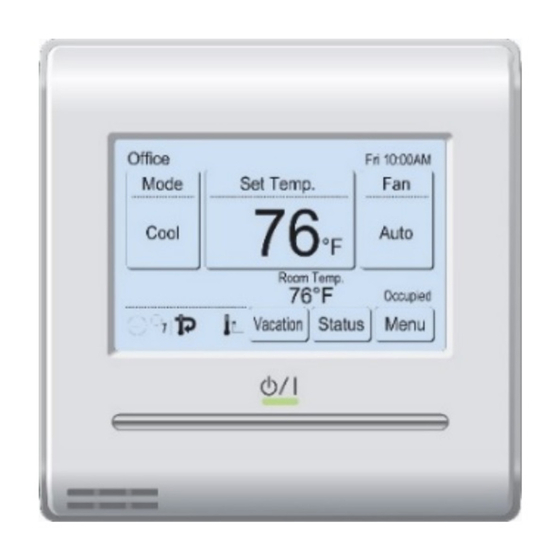
1 MONITOR The weekly timer is set. Refer to [3 SETTING] → [3-5 Weekly Timer Setting]. The set temperature automatic return setting is set. 1-1 Monitor Refer to [3 SETTING] → [3-6 Special Setting] → 1-1-1 Monitor mode screen [3-6-2 Set Temp. Auto Return]. It shows that it is time to clean the filter. Refer to [3 Monitor mode screen is the home screen of this unit. SETTING] → [3-10 Maintenance] → [3-10-3 Filter Sign Reset]. The temperature sensor of this unit is used. -
Page 7: Child Lock
• Economy: Set Temp. Limited: ON or OFF of the economy setting is displayed. Indoor unit temperature setting is limited by the Central controller. • Anti Freeze*: ON or OFF of the anti freeze setting is displayed. Energy Saving Operation: < Page 2 > The energy saving is set by the Energy Manager for Sys- tem Controller. -
Page 8: On And Off
2 CONTROL 2-2-2 Set the Temperature (1) Touch the [Set Temp.] on the monitor mode screen. 2-1 On and Off (2) “Set Temp.” screen is displayed. Adjust the room tem- (1) Press the [On/Off] button. perature with the [ ] or [ ]. Set Temp. Fri 10:00AM Set Temp. -
Page 9: Setting
3 SETTING (2) “Air Flow Direction Setting” Air Flow Direction Setting screen is displayed. When the [VT Setting] or [HZ Setting] is Setting Setting 3-1 Select the Setting Items touched, each setting screen is displayed. (1) Touch the [Menu] on the moni- Fri 10:00AM Back tor mode screen. -
Page 10: Individual Hold
3-3-3 Individual Hold • 3D flow cassette type The number of outlet port differs depending on the model. “Individual Hold” can be used only with cassette type indoor unit which supports this function. The air flow direction can Indoor Unit 1 (00-00) Indoor Unit 1 (00-00) Left Center 1 Center 2 Right Left Center Right be set for each outlet of single or multiple indoor units con- nected to this remote controller. -
Page 11: On Timer
3-4-1 On Timer Off Timer Fri 10:00AM Enable/Disable (1) Touch the [On Timer] on the Timer Setting Enable/Disable [Disable] Enable “Timer Setting” screen. When On Timer [Disable] the “Password Verification” Off Timer [Disable] Operation Stop Time [In 0.5 hr] Disable screen is displayed, enter the Auto Off Timer [Disable] password and touch [OK]. -
Page 12: Weekly Timer Setting (For Administrator)
(13) Touch the [OK] on the “Time Time Range Setting Fri 10:00AM Range Setting” screen. The Time Range [Range Spec.] Auto Off Timer Operation Stop Time Fri 10:00AM Fri 10:00AM display returns to the “Auto Off After the Manual Operation Enable /Disable [Enable] Start Time [08:40AM] Timer”... -
Page 13: Schedule Setting
(3) When the [OK] is touched, after a setting change screen NOTE is displayed, the display returns to the “Weekly Timer Setting screen format corresponds to the preference Setting” screen. of the “Display format Setting”. NOTE To disable use of a schedule already set, touch [None] at (8) Touch the [On/Off] on the screen of (2). -
Page 14: Day Off Setting
A bar is displayed above the Schedule 1 Setting Fri 10:00AM day of the week with a sched- Wed Thu Weekly Timer Setting Day Off Setting ule set. 08:00 AM On 28.0°c Enable Schedule [Schedule 1] 10:00 AM –– Cool 26.0°c 12:00 PM ––... -
Page 15: Economy
• Fan Control for Energy Saving* (for administrator): (6) Set the time and temperature Cool/Dry When the set temperature is reached during cooling by touching [ ] or [ ]. The Return Time Return Temp. operation, the fan operates intermittently and power is time can be set within the 10 28.0 saved. -
Page 16: Anti Freeze (For Administrator)
When the [OK] is touched, the display returns to the “Setting” screen. If the [Back] on the “Setting” screen is Auto Saving Fri 10:00AM Enable/Disable touched, the display returns to the “Temp. Range Set- Enable Enable/Disable [Disable] ting” screen. NOTE Absence Detection Time [In 30 min.] Disable... -
Page 17: Fan Control For Energy Saving (For Administrator)
When the [Back] on the “Human Sensor Setting” is When the item to be set is touched, the display switches touched, the display returns to the “Special Setting” to each setting screen. When each setting is complete screen. or canceled, the display returns to this screen. When [Back] is touched, the display returns to the “Main Menu”... -
Page 18: Backlight Setting
3-8-2 Backlight Setting 3-8-3 Contrast Setting (1) Touch the [Backlight Setting] (1) Touch the [Contrast Setting] on the “Preference” screen. Preference on the “Preference” screen. (2) “Contrast Setting” screen is displayed. Adjust the con- Panel Backlight Calibration Setting trast with [ ] or [ ]. Contrast Back Preference... -
Page 19: Language Setting
• RC Sensor Setting*: Set the Date and Time This setting uses the sensor of this unit to sense the (2) Touch the [Date and Time Setting] on the “Date Setting” room temperature. The room temperature can be screen. “Date and Time Setting” screen is displayed. sensed at a position, closer to the person than the (3) Touch the [Date] on the “Date and Time Setting”... -
Page 20: Temp. Unit Setting
(11) Touch the [Time Format] on the “Display Format Set- (a) Input area: ting” screen. When inputting more than 12 characters, “Over” is shown at the right end. (10) (11) (b) Character keys: Date Format Display Format Setting Touch the same key until the character to be used is dis- Fri 10:00AM Fri 10:00AM Date Format... -
Page 21: Display Item Setting
3-9-7 Display Item Setting (4) If the password is entered cor- Change Password rectly, the “Change Password” Enter New Password (1) Touch the [Display Item Set- screen is displayed. Initial Setting Page 2/ 3 ting] on the “Initial Setting” R.C. Sensor Master Indoor screen. -
Page 22: Lead Lag Setting
3-9-8 Lead Lag Setting Cycle setting (3) Touch the [Cycle] on the “Lead Lag” screen. (4) “Cycle” screen is shown. Set the term by touching [ ] or CAUTION [ ]. You can set the term “TEST” or from 1 day to 7 This is a simple function to keep the fixed room temperature with days in 1-day increments. -
Page 23: Maintenance (For Administrator)
Lag Operation Setting (3) If the password is entered correctly, the “Maintenance” If the room temperature remains high while after starting screen is displayed. The screen has 3 pages which are the Lead lag operation, the stopped indoor unit will start the switched by touching the [Next Page] or [Previous Page]. -
Page 24: Setting Status List
Erase the Error History 3-10-4 Version (1) Touch the [Erase All] on the “Error History” screen. (1) Touch the [Version] on the “Maintenance” screen. (2) A verification screen is displayed. When the [Yes] is (2) “Version” screen is displayed. touched after the history is cleared, the display returns When the [Back] is touched, the display returns to the to the “Error History”... -
Page 25: Operation Tips
4 OPERATION TIPS 4-1-5 Outdoor unit priority connection in heat pump system 4-1 Selectable Modes (for VRF system) (a) Refer to the following table: There are restrictions on the selectable modes depending on Status Selectable Not selectable the system configuration and operation status. Cooling priority is set by Cool, Dry Auto or Custom Auto, 4-1-1 Heat recovery system external input. -
Page 26: Others
5 OTHERS 5-1 Outline Dimensions Unit: mm (in) 120 (4-3/4) 20.4 (13/16) 5-2 Specifications Model Name UTY-RNRZ5 Input voltage DC 12 V Power consumption Max. 0.3 W 3.8 inch FSTN LCD Display (255 × 160 dots) with touch screen Usage temperature range 0 to 40 °C (32 to 104 °F) Usage humidity range 20 to 90 % (no condensation) Storage temperature range...
Need help?
Do you have a question about the UTY-RNRYZ5 and is the answer not in the manual?
Questions and answers
Electricity was cut off for 10 minutes , then back on. Two rooms displays not turning on
The Fujitsu UTY-RNRYZ5 display may not turn on after a power outage if the power was off for longer than approximately 7 days. In this case, the built-in battery that holds the date and time data may be depleted, requiring the date and time to be reset.
This answer is automatically generated
Could you please advise what is the error code 41 on your UTY-RNRY wall control. I cannot find any error codes in the manual. The green indicator light is also flashing.