
Related Manuals for Fujitsu UTY-RNRUZ5


Summary of Contents for Fujitsu UTY-RNRUZ5
- Page 1 REMOTE CONTROLLER (WIRED TYPE) OPERATION MANUAL WIRED REMOTE CONTROLLER Keep this manual for future reference. UTY-RNRUZ5 PART No. 9383992315...
-
Page 2: Table Of Contents
OPERATION MANUAL Initial Setting (for administrator)......18 3-8-1 Language Setting ........... 19 PART No. 9383992315 WIRED REMOTE CONTROLLER 3-8-2 Date Setting ............19 3-8-3 Temp. Unit Setting ..........20 3-8-4 R.C.Group Name Setting ........20 Contents 3-8-5 R.C. Sensor Setting ..........20 INTRODUCTION 3-8-6 Password Setting ........... - Page 3 Screen structure Mode Air Flow Direction Setting Cool Heat Setting Setting 2-2-1 Custom Auto Individual VT Hold Cancel Back Set Temp. Auto Off Timer Setting Fri 10:00AM 2-2-2 Cool Heat Enable /Disable [Enable] Operation Stop Time [in 30 min.] °F °F Time Range Setting [ –...
-
Page 4: Introduction
INTRODUCTION ■ SYSTEM OUTLINE 1 Terminology ■ SAFETY PRECAUTIONS System related terms (♦ is for VRF system) • The “SAFETY PRECAUTIONS” indicated in the manual (a) VRF system ♦: contain important information pertaining to your safety. Be VRF (Variable Refrigerant Flow) is a large multi-split sure to observe them. system that effectively air conditions a wide variety of spaces from large buildings to personal residences. -
Page 5: Password Configuration
2 Password configuration This unit can set the following 2 kinds of passwords: (a) Password This is a password for administrator. Password is re- quested by the setting which requires management. For a description of password setting and change, refer to [3. SETTING] →[3.8 Initial Setting]→[3-8-6 Password Setting] . (b) Installer password This password is requested for important settings at installation. -
Page 6: Monitor
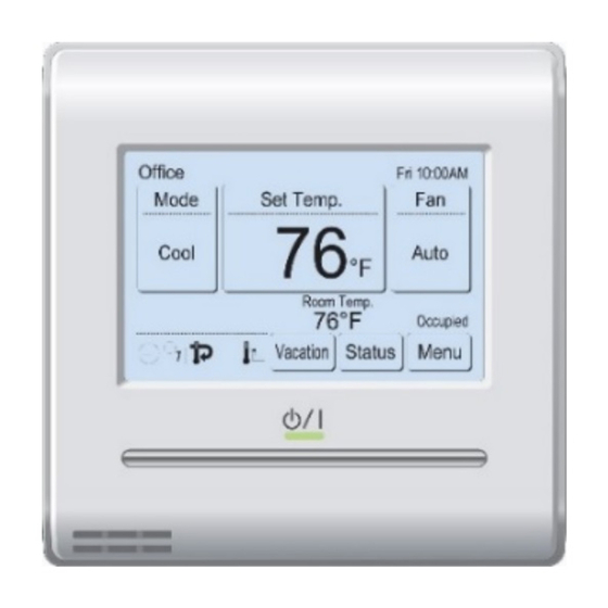
1 MONITOR (k) Status: When this is touched, the display switches to the “Status” screen. Refer to [1-1-2 Status Display]. 1-1 Monitor Vacation: When this is touched, the schedule is disabled and the 1-1-1 Monitor mode screen indoor unit remains unoccupied. Refer to [1-1-3 Vaca- tion]. -
Page 7: Status Display
1-1-2 Status display < Page 2 (to 3 or 4) > The remote controller and indoor unit setting status are dis- Status Status Page 3/ 4 Page 4/ 4 Special State Special State played. • Op. Controlled • Oil Recovery • Set Temp. Limited •... -
Page 8: Vacation
< Error Information screen > • Child safety lock set/reset: Press the Operation button for 4 seconds or more while [Error Information] is displayed only when there is an error touching an area outside the operation section of the moni- history. When the [Error Information] is touched, the display tor mode screen (no response even if touched). -
Page 9: Control
2 CONTROL • The mode cannot be changed during Away operation. Select the occupied state. • [Custom Auto] mode can be used in the R.C. Group 2-1 Operation On/Off to which Master Indoor Unit is set. It is not displayed (Occupied/Unoccupied) at other R.C. -
Page 10: Setting
3 SETTING NOTES • When using this unit together with a wireless remote 3-1 Select the Setting Items controller, the air flow direction of the indoor unit may not match the direction indicated on this unit. (1) Touch the [Menu] on the moni- • W hen the airflow direction is set with combination use Fri 10:00AM tor mode screen. -
Page 11: Auto Off Timer Setting
Air Flow Direction Setting Individual VT Hold Auto Off Timer Enable/Disable Page 1/ 2 Fri 10:00AM Unit 1 Unit 2 Unit 3 Unit 4 Enable /Disable [Disable] Enable 01-01 01-02 01-03 01-04 Setting Operation Stop Time [In 30 min.] Unit 5 Unit 6 Unit 7 Unit 8... -
Page 12: Weekly Timer Setting (For Administrator)
(11) Touch the [End Time] on the “Time Range Setting” 3-4-1 Enable Schedule screen. Select the schedule to be used (12) “End Time” screen is displayed. Set the End Time by touching [ ] or [ ]. (1) Touch the [Enable Schedule] on the “Weekly Timer Set- ting”... - Page 13 (6) The items that can be set for one time are the [Op. (11) When the [OK] on the screen Monday Page 1/ 3 Time], [Status], and [Set. Temp]. When each item is of (5) is touched, the display 08:00 AM Cool °F /Heat...
-
Page 14: Day Off Setting
3-4-3 Day Off Setting • Away Setting (for administrator): Set the operation start temperature at Unoccupied. To use this function, “Used” must be set by “R.C. Sensor Set the day of the week of which Weekly Timer is to be Setting”. Refer to [3-8 Initial Setting]→[3-8-5 R.C. temporarily disabled. When the set day has passed, the Sensor Setting]. setting is cleared. • Human Sensor Setting* (for administrator): “Human Sensor” detects the absence of a person in (1) Touch the [Day Off Setting] on the “Weekly Timer Set- the room and performs the following energy saving op- ting”... -
Page 15: Set Temp. Range Setting (For Administrator)
When the [OK] is touched, the display returns to “Set Set the Lower Limit and Upper Limit Temp. Auto Return” screen. (4) Touch the [Lower Limit - Upper Limit] on the “Set Temp. Range Setting” screen. Set the Return Time and Temperature (5) “Setting” screen is displayed. Touch the [Cool/Dry] or (4) Touch the [Return Time/Return Temp.] on the “Set [Heat] on the “Setting”... -
Page 16: Away Setting
3-5-5 Away Setting 3-5-6 Human Sensor Setting (for administrator) (1) Touch the [Human Sensor Setting] on the “Special Set- (1) Touch the [Away] on the “Spe- Special Setting Page 2/ 2 ting” screen. When the “Password Verification” screen is cial Setting” screen. When the Human Sensor Away Setting displayed, enter the password and touch the [OK]. “Password Verification” screen Setting was displayed, enter the pass-... -
Page 17: Fan Control For Energy Saving (For Administrator)
3-6 Summer Time (Daylight Saving Time) Setting (for administrator) Auto Off Fri 10:00AM Enable/Disable Enable/Disable [Disable] Enable The time display and timer operation are 1 hour earlier than usual. Absence Detection Time [In 24 hr] Disable (1) Touch the [Summer Time Cancel Cancel Main Menu Page 2/ 2 Setting] on the “Main Menu”... -
Page 18: Panel Calibration
3-7-1 Panel Calibration 3-7-2 Backlight Setting (1) Touch the [Backlight Setting] (1) Touch the [Panel Calibration] on the “Preference” Preference on the “Preference” screen. screen. Panel Backlight Calibration Setting (2) “Panel Calibration” screen is displayed. Touch the [Start] on the “Panel Calibration” screen. Contrast Back Preference... -
Page 19: Contrast Setting
Apply the setting • Date Setting: The date and time display format are set. When the (8) After setting is complete, power is turned off, the date and time data hold time Backlight Setting touch the [OK] on the “Back- by built-in battery is approximately 7 days. When the Enable/Disable [Enable] light Setting” screen. power is turned off for longer than this, the date and Automatic Off Time [30s]... -
Page 20: Language Setting
3-8-1 Language Setting When the [OK] is touched, the display returns to the “Date and Time Setting” screen. (1) Touch the [Language Setting] NOTE Initial Setting Page 1/ 4 on the “Initial Setting” screen. Language Setting Date Setting “Language Setting” screen is Setting screen format corresponds to the preference of the “Display format Setting”. -
Page 21: Temp. Unit Setting
3-8-3 Temp. Unit Setting 3-8-5 R.C. Sensor Setting (1) Touch the [Temp. Unit Setting] on the “Initial Setting” (1) Set the [R.C. Sensor Setting] on the “Initial Setting” screen. screen. (2) “Temp. Unit Setting” screen is displayed. Select the [°F] (2) “R.C. Sensor Setting” screen is displayed. Touch the or [°C]. -
Page 22: Display Item Setting
Password request to the setting item On/Off is set. (5) Touch the [Change Setting] Display Item Setting Filter Sign Password Setting on the “Password Setting” Filter Sign [Visible] Visible Change Password screen. Room Temp. [Invisible] Invisible Change Setting Cancel Cancel Back When the [OK] is touched, the display returns to the “Change Setting”... -
Page 23: Optimum Start Setting
3-8-9 Optimum Start Setting (2) The screen has 2 pages which are switched by touching the [Next page] or [Previous Page]. (1) Touch the [Optimum Start Setting] on the “Initial Setting” Lead Lag Setting Lead Lag Setting Page 1/ 2 Page 2/ 2 screen. -
Page 24: Maintenance (For Administrator)
3-9 Maintenance (for administrator) Backup Units Lead Lag Setting Page 2/ 2 Verification, operation, and setting for administrator informa- Backup Units [2/16] 2 Units tion are performed. Lag Operation [Enable] (1) Touch the [Maintenance] on the “Main Menu” screen. 1 Unit (2) When “Password Verification” screen is displayed, enter Previous Cancel Back Page the Password (or Installer Password) and touch [OK]. -
Page 25: Error History
3-9-1 Error History 3-9-3 Filter Sign Reset (1) Touch the [Filter Sign Reset] on the “Maintenance” (1) Touch the [Error History] on Maintenance Page 1/ 3 screen. the “Maintenance” screen. Setting Error History After the data transmission screen is displayed, the Status List “Filter Sign Reset”... -
Page 26: Operation Tips
(3) Select the category about which you want to monitor. 4-1-3 RB priority connection in heat recovery system (4) If you select [Sensor ID], input the ID of the monitoring item on the next screen. (a) For indoor units or RB groups by RB priority connec- tion, refer to the following table: Status Selectable... - Page 27 4-4 Deadband and set temperature 5-2 Specifications The Cool and Heat set temperature difference at Custom Model Name UTY-RNRUZ5 Auto cannot be less than the deadband set value. If the Cool Input voltage DC 12 V and Heat set temperature difference is the same as the Power consumption Max. 0.3 W deadband set value, the Heat setting drops by the amount 3.8 inch FSTN LCD...
Need help?
Do you have a question about the UTY-RNRUZ5 and is the answer not in the manual?
Questions and answers
what app controls this unit
We have 2 Fujitsu 36KPAS1 heat pumps. Right now all we use is the remote control provided with the unit. Question if we install the touch panel wired controller UTY-RNRUZ5 Can we also use the remote-control to operate the indoor units? We will schedule the weekly schedule Sunday mornings and Wednesday events but want the capability to manually start the indoor units for times other than the weekly schedule.