Table of Contents
Advertisement
Quick Links
Advertisement
Table of Contents

Subscribe to Our Youtube Channel
Related Manuals for La Marche ULTRA SERIES


Summary of Contents for La Marche ULTRA SERIES
- Page 1 La Marche Manufacturing Company | www.lamarchemfg.com ULTRA SERIES CHARGER Installation and Operation Manual 106 Bradrock Dr. Des Plaines 60018-1967 CPN 134372 Instruction Drawing Number: P25-LUSC-1 Tel: 847 299 1188 Fax: 847 299 3061 Revision A03 Rev. Date: 02/17 ECN: 21367 ...
-
Page 2: Important Safety Instructions
Important Safety Instructions Before using this equipment read all manuals and other documents related to this unit and other equipment connected to this unit. Always have a copy of a units manual on file nearby, in a safe place; if a replacement copy of a manual is needed it can be found at the www.lamarchemfg.com. -
Page 3: Unit Location
In the unlikely event of internal damage, please inform the carrier and contact La Marche for advice on the risk due to any damage before installing the product. Verify that you have all the necessary parts per your order for proper assembly. -
Page 4: Table Of Contents
Table of Contents Important Safety Instructions ........................ii Table of Contents ............................. iv 1. Ultra Series Charger General Description .................... 5 Standard Features ..........................5 Table 1 – Front Panel Overview ....................... 5 2. Installation ............................6 ... -
Page 5: Ultra Series Charger General Description
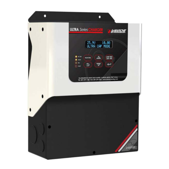
Ultra Series Charger Description General Description The La Marche Ultra Series charger is a high performance charger, which utilizes high frequency technology. It is specially designed to meet the requirements of charging ultra capacitors, as well as to charge the batteries used in Engine starting applications. The charger provides protection against battery reverse connection, high DC voltage, input voltage variation and surges. -
Page 6: Installation
Refer to figure 2 for mounting dimensions. Figure 2 – Mounting Dimensions After the Ultra series charger is mounted, the input, output and alarm connections can be made. Electrical Connections Unscrew the front cover to access the Input, Output and Alarm connectors. See the Figure 3 and Figure 4 in section 3.1 and 3.2 on the next page for reference. -
Page 7: Input Ac Connections
Input AC Connections Connect AC wiring to the equipment per the image shown below. Refer to section 3.3 for recommended wire sizes. Figure 3 – Input Connections Output DC Connections Connect Ultracap/battery DC cables to the equipment per the image shown below. Refer to section 3.3 for recommended wire sizes. -
Page 8: Power Cabling Guide
Power Cabling Guide Use the following formulas and tables to determine proper wire size for minimal voltage drop. Table of Conventions = Cross section of wire in circular MIL area = Ultimate drain in amperes = Conductor loop feet MaxAmp = Maximum allowable amperes for given voltage drop = Allowable voltage drop = 11.1 for commercial (TW) copper wire (KS5482-01) -
Page 9: Alarm Connections
Table 4 – Alarm Relay Logic INPUT/OUTPUT PROTECTION: AC Input Fuses: The Ultra Series charger is equipped with two AC input fuses. DC Output Fuse: The Ultra Series charger is equipped with one DC output fuse. Refer to unit specifications (Section 7) for fuse size information. -
Page 10: Temperature Compensation
Temperature Compensation Ultra Series charger is equipped with an External Temperature Compensation feature. The charger is provided with the compensation circuit and a 24 foot long temperature probe. The natural voltage of the battery changes as a function of temperature change. As the Ultracap/ battery temperature rises, the effective voltage of the Ultracap/battery decreases. -
Page 11: Operation
Operation 5.1. Front Display Panel : Figure 7 – Front Display Panel (A) LCD Panel: Displays the status and output parameters of the system. In normal operation the parameters displayed are as follows: ● Charger Output Voltage ● Charger Output Current ●... -
Page 12: Initial Setup
Once all AC, DC and alarm connections have been made, apply AC power by closing the upstream AC breaker. The unit will automatically power up. At the initial startup the ULTRA SERIES CHARGER will run at the default settings (26 Volt Output for 24V units and 13 Volt output for 12V units; current Limit is set to 105%). -
Page 13: User Menu
5.3 User Menu: Symbols: # Default Value Press MENU/ENTER button to advance to the right and EXIT ( button to navigate to the left. Use UP/DOWN buttons to navigate between settings and settings values. -
Page 14: Troubleshooting
If this message appears on the display, please Comm. Fail consult La Marche technical support team. Note: If any of the above mentioned or any other fault condition continue to occur, please contact La Marche technical support at 847-299-1188. -
Page 15: Technical Specifications
Technical Specifications AC input Voltage and frequency Auto ranging 105-264 VAC, 45-65 Hz Rated Current 2.6A @120VAC, 1.4A @240VAC (for 24V 10A output mode) Input protection AC Fuse (250V, 5A Glass type) Inrush limiting Inrush current limited NTC Efficiency Exceeds CEC-400-2012-019-CM requirements Power factor Input Terminals Terminal blocks (Push-In Springable type);... -
Page 16: Document Control And Revision History
Document Control and Revision History Part Number: 134372 Instruction Number: P25-USC-1 Issue ECN: 21203-1 21367 / 02-17 21341 / 01-17 21203-1 / 08-16 21203 / 07-16...
Need help?
Do you have a question about the ULTRA SERIES and is the answer not in the manual?
Questions and answers