Table of Contents
Advertisement
Quick Links
La Marche Manufacturing Company
www.lamarchemfg.com
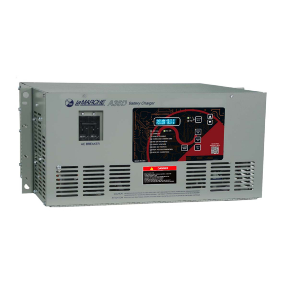
A36D
Controlled Ferroresonant Rectifier /
Power Supply
106 Bradrock Dr. Des Plaines 60018-1967
Tel: 847 299 1188
Fax: 847 299 3061
Installation and Operation Manual
CPN 129389
Instruction Drawing Number: P25-LA36DSERIES-2
Revision A06
Rev. Date: 03/18
ECN: 21738
Advertisement
Table of Contents
Troubleshooting

Subscribe to Our Youtube Channel
Related Manuals for La Marche A36D


Summary of Contents for La Marche A36D
- Page 1 La Marche Manufacturing Company www.lamarchemfg.com A36D Controlled Ferroresonant Rectifier / Power Supply Installation and Operation Manual 106 Bradrock Dr. Des Plaines 60018-1967 Instruction Drawing Number: P25-LA36DSERIES-2 Tel: 847 299 1188 Fax: 847 299 3061 CPN 129389 Revision A06 Rev. Date: 03/18...
- Page 2 Important Safety Instructions Before using this equipment, read all manuals and other documents related to this charger and other equipment connected to this charger. Always have a copy of a charger’s manual on file nearby in a safe place; if a replacement copy of a manual is needed, it can be found at www.lamarchemfg.com.
- Page 3 If any damage is observed, take pictures and contact the carrier immediately to file a damage claim. Contact La Marche for a Return Material Authorization number to have the charger sent back for evaluation and repair.
-
Page 4: Table Of Contents
Installation ............................3 Mounting the A36D ........................3 2.1.1 Rack-Mounting the A36D ............Error! Bookmark not defined. 2.1.2 Floor-Mounting the A36D (All Enclosures) .................. 5 Changing Transformer Taps ......................6 ... - Page 5 Checking Capacitors ....................... 31 Appendix A: A36D Specifications ....................... 32 Appendix B: A36D Current Draw and Feeder Breaker Sizes ................33 Appendix C: A36D Heat Losses ......................... 35 Appendix D: Manufacturer’s Warranty ....................... 36 ...
-
Page 6: Table Of Figures
Figure 5 - 33 Enclosure Bolt Pattern .............. Error! Bookmark not defined. Figure 6 - A36D Enclosure Footprint .............. Error! Bookmark not defined. Figure 7 - Input Terminals Connection Schematic (240VAC Input Shown) ............6 Figure 8 - User Connections to Alarm Contacts on S2A-198 Board ..............9 ... -
Page 7: Model Scope/General Description
Form “C” contacts. The A36D is offered with DC output voltages of 12, 24, 48VDC with output currents from 6 to 200 Amps. These chargers may be powered with 120, 208, 220, 240, 380, or 480VAC. -
Page 8: Equipment Handling
Storing the A36D If the A36D is to be stored for more than a few days after delivery, it should be stored within its shipping container. The location chosen for storage should be within an ambient temperature of -40 to 185° F (-40 to 85°... - Page 9 Ampere Rating Output Frequency Voltage 75 ADC 100 ADC 150 ADC 200 ADC 200 ADC 300 ADC 400 ADC 33E Case 33E Case 9D Case 9D Case 110 lbs 130 lbs 145 lbs 180 lbs 60 Hz 49.9 kg 59 kg 65.8 kg 81.6 kg 12 VDC...
-
Page 10: Installation
Verify the weight of the A36D charger using Tables 1, 2 and 3, and the method of mounting using Table 4 below. The location chosen for the charger should be within an ambient temperature range of 32 to 122˚F (0 to 50˚C) with... -
Page 11: Rack-Mounting The A36D
Rack-Mounting the A36D The A36D can be installed in most relay racks with standard EIA hole spacing. If a relay rack is needed, they are available for purchase from La Marche. The 4D, 9E, 33, 33E, and 39 enclosures are shipped from the... -
Page 12: Floor-Mounting The A36D (All Enclosures)
Floor-mounting the 43, 44, and 72 enclosures is standard. To floor-mount the A36D, install four to six anchor bolts into the floor. Place the charger on the bolts, add appropriate mounting hardware, and tighten securely. The figure below shows the footprint and the bolt size of each A36D enclosure style. All dimensions are in inches. -
Page 13: Changing Transformer Taps
NOTE: The A36D is wired at the factory for 240 VAC, except on special request. Before changing the PT taps, be sure that AC supply and DC loads to the A36D are turned off and locked out. Verify that no voltage is present by using a voltmeter at all input and output terminals. Turning off the AC and... -
Page 14: Ac Input Connections
Table 6 – AC/DC & Ground Wire Size Minimum Requirements (All wires specified in the table are rated at 90 °C or 194 °F) NOTE: These are recommended sizes per La Marche Standards. The National Electrical Code (NEC) and Local Wiring Codes must be followed. -
Page 15: Dc Output Connections
DC Output Connections Before making any of DC output connections, make sure you have read and fully understand the DC Connection Procedure below. Select proper size for the DC wiring from the wire size table on the previous page. If the distance between the charger’s DC output and the DC load exceeds 10 feet, use the Power Cable Guide below to minimize the voltage drop across the wire distance. -
Page 16: Alarm Connections
Alarm Connections Seven alarm relays (and 9 alarm LEDs) are included as a standard feature of the A36D. The included alarms are Low DC Current, Low DC Voltage, High DC Voltage, High Voltage Shutdown, AC Failure, Open DC Protection, and Summary alarm. Each alarm includes two sets of form ‘C’ contacts, enabling the user to connect multiple remote annunciators. -
Page 17: Alarm Connection Procedure
Alarm Connection Procedure Before making any connections to the A36D, ensure that the AC power is off at the main breaker box and the charger’s breakers are off. Verify that no voltage is present by using a voltmeter at all input and output terminals. -
Page 18: Understanding The Alarms
2.5.2 Understanding the Alarms HIGH VOLTAGE SHUTDOWN ALARM will trigger and the red “HIGH VOLTAGE SHUTDOWN” LED will turn on if the output DC voltage of the charger rises above the alarm threshold for longer than 20 seconds and there is load on the charger. -
Page 19: Installing External Temperature Compensation (Option 11W)
External Probe Connection Procedure Before making any connections to the A36D, ensure that the AC power is off at the main breaker box and the charger’s breakers are off. Verify that no voltage is present by using a voltmeter at all input and output terminals. -
Page 20: Enabling Load Sharing
Load Sharing Procedure Before making any connections to the A36D, ensure that the AC power is off at the main breaker box and that all of the chargers’ breakers are off. Verify that no voltage is present by using a voltmeter at all input and output terminals. -
Page 21: Dnp 3.0 / Modbus Scada Interface (Option 21P/21Q)
Communication Interface Connection Procedure Before making any connections to the A36D, ensure that the AC power is off at the main breaker box and the charger’s breakers are off. Choose which port to use for connection (Ethernet, RS232, and/or RS485 – refer to Figure 18). -
Page 22: Operation
Factory Settings The factory settings of the A36D are based on the model number. Unless otherwise specified, all chargers are set at the factory with the following settings: Parameter... -
Page 23: Starting/Stopping The A36D
The A36D is available with an LCD or VFD digital control board as Options 550 or 551 respectively. These options replace the LED analog control board that is standard to the A36D. The digital control board is a more attractive and user-friendly option, with many additional features over the standard LED analog control board. -
Page 24: Selecting The Charging Mode
The A36D has two different settings for DC output voltage, Float Mode and Equalize Mode. Float charging mode is used for all normal battery charging needs. In the case of the A36D, the Float Mode can also be used for battery elimination (directly powering the DC load from the A36D). -
Page 25: Settings Menu
3.4.1 Settings Menu In the Settings Menu, the user can access and change various parameters used by the A36D. To access the Settings Menu, press the MENU button, select “Settings Menu”, and press the ENTER button. Once in the Settings Menu, the user can navigate the menus with the up and down arrows. To enter a submenu, use the ENTER button. -
Page 26: 3.4.1.3 Advanced Settings
Alarm 150.0 V NOTE: Alarm threshold defaults are based on the charger output. The alarm threshold values shown above are not representative of the default values for any specific A36D charger. Summary Alarm Selects The Summary alarm selects setting allows the user to choose whether or not to include the Low Current Alarm and AC Failure Alarm as part of the Summary Alarm. - Page 27 NOTE: The HVSD alarm latches by default and cannot be changed. Temperature Compensation Settings Temperature Compensation is a standard feature of the A36D charger. Temperature Compensation adjusts the output voltage of the charger based on the temperature at the probe. To enable Temperature Compensation, select “Temp.
- Page 28 Communications Settings The communication settings menu changes depending on the type of communication protocol used in the charger. For details on connection instructions as well as operation instructions, refer to the SCADA Interface instruction manual included with the charger. Chargers with DNP 3.0 Communication Protocol (Option 21P) Setting ...
-
Page 29: 3.4.1.4 Return To Defaults
Test LEDs The Test LEDs menu allows the user to run a basic lamp test on the A36D. After selecting this menu, press the “ENTER” button to light all of the LEDs on the display membrane. To end the LED test, press back. -
Page 30: A36D Customer Configuration Menu Structure
A36D Customer Configuration Menu Structure... -
Page 34: Service
Before working inside the A36D, ensure the AC power is off at the main breaker box and the battery has been removed from the charger’s DC output terminals, either by removing the battery cables or exercising the battery disconnect. -
Page 35: Troubleshooting Procedure
La Marche Service Technicians are available to help with troubleshooting or with scheduling charger service. When calling for a service inquiry or for troubleshooting assistance, be sure to have all of the following information on hand: 1. -
Page 36: Troubleshooting Chart
Refer to Section 4.3.3. (SD1) Shorted Battery Cells or Customer Remove all loads and batteries from Equipment A36D and confirm A36D functionality. Shorted Output Cables Inspect DC cables for shorts. DC Breaker Trips Defective Filtering Capacitors Refer to Section 4.3.4. -
Page 37: Ground And Short Circuit Test
Refer to Section 4.3.3. Ordering Replacement Parts Contact La Marche to place an order for spare or replacement parts. To order replacement parts; please provide the model and serial number of the charger, the part needed, and the quantity required. -
Page 38: Troubleshooting And Replacing Power Silicon Diodes/Modules
Troubleshooting and Replacing Power Silicon Diodes/Modules 1. On the ohmmeter, set the switches on “ohms”, “DC”, and “Rx100” scale and isolate one end of the diode by disconnecting the wires attached to the nipple (or pigtail) end of the diode (only one end of the diode must be disconnected). -
Page 39: Appendix A: A36D Specifications
± 0.5% from no load to full load over the specified input voltage, frequency and ambient Regulation temperature range. Load Sharing When connected identical A36D chargers are forced to share the load equally (within ± 5%). Meters Digital Meter Display PROTECTION... -
Page 40: Appendix B: A36D Current Draw And Feeder Breaker Sizes
Appendix B: A36D Current Draw and Feeder Breaker Sizes (Single Phase) Single Phase 60 Hz 50 Hz Model AC Current Draw (Recommended Feeder AC Supply Breaker) Number Amps ABD1 BLD1 5BL1 120V 120/240/208V 240/220/208V 240/220V A36D-15-12V 2.4 (5) A36D-20-12V 3.2 (7.5) A36D-25-12V 4.0 (7.5) - Page 41 A36D Current Draw and Feeder Breaker Sizes (Three Phase) Three Phase 60 Hz 50 Hz Model Number AC Current Draw (Recommended Feeder AC Supply Breaker) Amps BD3 (240/208V) C3 (480V) 5G3 (380V) A36D-200-24V 16.9/19.5 (25) 8.5 (15) 10.7 (15) A36D-300-24V 25.4/29.3 (35)
-
Page 42: Appendix C: A36D Heat Losses
Appendix C: A36D Heat Losses (Based on 85% efficiency & 0.9 Power Factor at rated load) Model Number Watts In Watts Out Watts Lost BTU/Hr. A36D-15-12V A36D-20-12V A36D-25-12V A36D-30-12V A36D-50-12V A36D-75-12V 1296 1043 A36D-100-12V 1680 1320 1227 A36D-150-12V 1980 3068... -
Page 43: Appendix D: Manufacturer's Warranty
If the Extended Warranty is purchased, the parts required for repair will also be at no cost but La Marche will notify the Purchaser of the costs of Labor to replace the defective part(s). -
Page 44: Appendix E: Manufacturer's Extended Parts Warranty
Should minor adjustments be required, the local La Marche sales representative should be contacted to provide this service only. All sales are final. Only standard La Marche units will be considered for return. A 25% restocking fee is charged when return is factory authorized. Special units are not returnable. -
Page 45: Appendix F: Document Control And Revision History
Appendix F: Document Control and Revision History Part Number: 129389 Instruction Number: P25-LA36DSERIES-2 Issue ECN: 20117-4 – 09/13 21738 – 03/18 21655 – 12/17 21063 – 10/17 21063 – 02/16 21183-2 – 12/16 20117-09/13...
Need help?
Do you have a question about the A36D and is the answer not in the manual?
Questions and answers