Table of Contents
Advertisement
Quick Links
This manual is subject to change without notice. You may obtain the newest version of the manual at www.lamarchemfg.com
106 Bradrock Dr. Des Plaines, IL 60018-1967
Tel: 847 299 1188
Fax: 847 299 3061
La Marche Manufacturing Company
www.lamarchemfg.com
A77 Series
Microprocessor Controlled SCR
Filtered/Battery Eliminator Filtered Charger
Installation and Operation Manual
CPN 129767
Instruction Drawing Number: P25-LA77-1
Revision A02
Rev. Date: 08/15
ECN: 20924
i
Advertisement
Table of Contents
Troubleshooting

Subscribe to Our Youtube Channel
Related Manuals for La Marche A77


Summary of Contents for La Marche A77
- Page 1 La Marche Manufacturing Company www.lamarchemfg.com A77 Series Microprocessor Controlled SCR Filtered/Battery Eliminator Filtered Charger Installation and Operation Manual This manual is subject to change without notice. You may obtain the newest version of the manual at www.lamarchemfg.com 106 Bradrock Dr. Des Plaines, IL 60018-1967...
-
Page 2: Electrical Safety
Important Safety Instructions Before using this equipment read all manuals and other documents related to this unit and other equipment connected to this unit. Always have a copy of a units manual on file nearby, in a safe place; if a replacement copy of a manual is needed it can be found at the www.lamarchemfg.com. -
Page 3: Unit Location
In the unlikely event of internal damage, please inform the carrier and contact La Marche for advice on the risk due to any damage before installing the product. Verify that you have all the necessary parts per your order for proper assembly. -
Page 4: Table Of Contents
Installing the A77 ..........................3 Mounting the A77 ........................3 1.1.1 Wall-Mounting the A77 (10 & 477 Only) ..................4 1.1.2 Floor-Mounting the A77 (All Enclosures) ..................5 1.1.3 Rack-Mounting the A77 ......................6 ... - Page 5 Operation ............................19 Starting the A77 ........................19 Factory Settings ..........................19 2.1.1 Checking the Installation ......................19 2.1.2 Start-Up Sequence ......................... 19 Digital Control Board ......................... 20 Selecting the Charging Mode ...................... 21 ...
- Page 6 Data Logging ............................ 29 Events Only Logging ........................29 Interval Logging ........................29 Installing/Removing the SD Card ....................29 Reading the Log File ........................29 Reflected Harmonics………………………………………………………………………………………………………………..31 Service ............................. 32 ...
-
Page 8: Table Of Figures
Figure 13 – A77 Front Panel ........................20 Figure 14 – Example Events Log ....................... 29 Table 1 - Available mounting methods for each of the A77 enclosure sizes ............. 3 Table 2 - Available Rack Mount Configurations ..................... 6 ... -
Page 9: Model Scope/General Description
Storing the A77 If the A77 is to be stored for more than a few days after delivery, it should be stored within its shipping container. The location chosen for storage should be within an ambient temperature of -40 to 185° F (-40 to 85°... -
Page 10: Installing The A77
Verify the weight of the A77 charger using Appendix A or Appendix B, and the method of mounting using Table 1 below. -
Page 11: Wall-Mounting The A77 (10 & 477 Only)
To wall-mount the A77, install four 0.25 in (6.4 mm) bolts on the wall rated to support the charger weight plus a safety factor of at least two times (for the 477 enclosure 6 bolts are needed). Place the A77 on the bolts, add appropriate mounting hardware and tighten. -
Page 12: Floor-Mounting The A77 (All Enclosures)
Floor-Mounting Procedure To floor-mount the A77, install four bolts into the floor. Place the A77 on the bolts, add appropriate mounting hardware, and tighten securely. The images below show the footprint and hardware required of each A77 enclosure style. -
Page 13: Rack-Mounting The A77
1.1.3 Rack-Mounting the A77 The A77 can be installed in most relay racks with standard EIA hole spacing. If a relay rack is needed they are available for purchase from La Marche. The 10 & 477 enclosures are shipped from the factory with the (The same bracket is used for wall mounting necessary brackets installed for rear mounting on a 19”... -
Page 14: Changing Transformer Taps
(Special chargers can be ordered upon request.) Before wiring AC power to the A77, check the wiring of the power transformer PT, to be sure it is connected for the correct AC input voltage. The A77 accepts standard input voltages of 120, 208 or 240 VAC by changing the connections to the input terminals. -
Page 15: Making The Ac Input Connections
Making the AC Input Connections Before making any connections to the A77 ensure that the AC Power is off at the main breaker box and that both of the charger’s breakers are off. Check that the source voltage and frequency matches the voltage and frequency listed on the charger nameplate. -
Page 16: Making The Dc Output Connections
Making the DC Output Connections Before making any of DC output connections make sure you have read and fully understand the DC Connection Procedure below. Select proper size for the DC wiring from the wire size table on the previous page. If the distance between the charger’s DC output and the DC load exceeds 10 feet, use the Power Cable Guide below to minimize the voltage drop across the wire distance. -
Page 17: Alarms
1.5.1 Standard Alarms Two alarm relays (and 11 alarm LEDs) are included as a standard feature of the A77. The included alarm relays are a Summary alarm and an AC Failure alarm. Each alarm includes one set of form C contacts enabling the customer to connect remote annunciators using connector J1 of the S2A-368S display and control card, refer to Figure 7. - Page 18 LOW ACV ALARM will trigger if the AC voltage to the charger drops below 90% of the nameplate rating AC ON for longer than 5 seconds, the green “ ” LED will turn flash. There are no alarm contacts associated with this alarm.
-
Page 19: Discrete Alarm Relay Board (Option 46R)
Discrete Alarm Contacts All alarms contacts for the A77 are designed to be fail-safe. In other words, if both the AC and DC power are removed, each alarm will be indicating in its correct state. To accomplish this, certain alarm relays are de- energized on failure (such as AC Failure), and certain alarm relays are energized on failure (such as High DCV). -
Page 20: Alarm Connection Procedure
1.5.4 Alarm Connection Procedure Before making any connections to the A77 ensure that the AC Power is off at the main breaker box and that both of the charger’s breakers are off. Verify that no voltage is present by using a voltmeter at all input and output terminals. -
Page 21: Temperature Compensation (Option 11W/11Y)
1.6.1 External Probe Connection Procedure Before making any connections to the A77 ensure that the AC Power is off at the main breaker box and that both of the charger’s breakers are off. Verify that no voltage is present by using a voltmeter at all input and output terminals. -
Page 22: Enabling Load Sharing
Note: Before making any connections to the A77 ensure that the AC Power is off at the main breaker box and that all of the chargers’ breakers are off. Verify that no voltage is present by using a voltmeter at all input and output terminals. -
Page 23: Remote Equalize Procedure
1.7.3 Remote Equalize Procedure When chargers are connected for Load Sharing, they must also be set up to switch into equalize at the same time. This can be accomplished by using the remote equalize function of the charger. In addition to wiring the Load Share wire, the chargers’... -
Page 24: Ground Detection
The purpose of ground detection is to determine if the battery or loads have become grounded. Ground detection is available on all A77 chargers. If the battery or loads are set up as floating, it is recommended that ground detection be enabled. When ground detection is enabled a positive or negative ground fault indicator will energize upon detection of a ground. -
Page 25: Ac Breaker Trip On Hvsd (Option 19T)
AC Breaker Trip on HVSD (Option 19T) Option 19T uses a Shunt Trip and an External Timer Circuit (S2A-412) to trip the AC Breaker when the charger goes into a High Voltage Shutdown Alarm State. In order to reset the HVSD alarm the AC and DC breakers must be switched off (opened). -
Page 26: Operation
Note: V/C – Volts/Cell, LA – Lead Acid, VRLA – Valve Regulated Lead Acid, NC – Nickel Cadmium 2.1.1 Checking the Installation Before attempting to start up the A77 check and verify that all connections are correct. Check that all terminations and contacts are tightened securely. Check that the transformer is set for the correct voltage and that the input frequency matches the nameplate or the charger. -
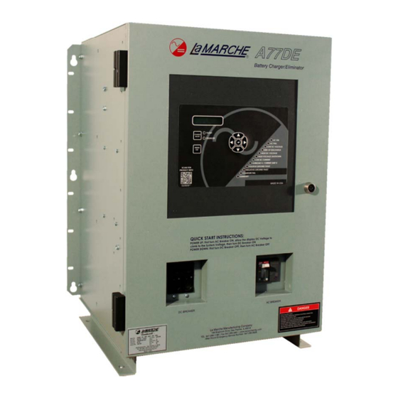
Page 27: Digital Control Board
Figure 13 – A77 Front Panel After the A77 has completed the startup sequence, the “AC ON” and “FLOAT” LEDs should be on and the display should show the output voltage and current as pictured above in Figure 13. The parameter displayed can be changed by pressing either the UP or DOWN arrows on the membrane. -
Page 28: Selecting The Charging Mode
The float mode can also be used for battery elimination, which means directly powering the DC load from the A77. Equalize mode is used when it is necessary to equalize (or balance) the level of charge across all cells present in the battery. Consult the battery manufacturer for the proper equalize procedures and parameters. -
Page 29: Settings Menu
“Exit and Save Settings?” displays, and follow the prompts. See for more details. In addition, settings can be configured remotely. Remote configuration requires that the A77 have an optional communication card. For more information and instructions on remote configuration, see the communications The communications instructions are included as part of the manual package only if a instructions. -
Page 30: Save/Load Configuration
Load Config from the card, it is recommended to use a blank Micro SD card for use. A memory card only needs to be initialized once. After it has been initialized in an A77 charger, >Load Config it can be used in any other A77 charger without being initialized again. -
Page 31: Equalize Voltage
The Current Limit is adjustable between 50% and 115% of Temp. Comp. the nameplate rating, and the default setting is 110%. The current limit setting is Ex: A 30A A77 charger has a current limit adjustment of 15-34.5A. adjustable in 0.1A increments. -
Page 32: Temperature Compensation
Alarm threshold defaults above are based on a 240Vac charger input and a 60L charger output. The alarm Note: Ground threshold values shown above are not representative of the default values for all A77 chargers. Fault Alarm adjustment is only available on chargers that are built with Option 19U. Note: The Default Low... -
Page 33: Alarm Delays
3.6.2 Alarm Delays The Alarm Delays setting allows the customer to determine the time delay between the alarm condition and alarm indication. If an alarm condition returns to normal before the delay time, the alarm will not indicate. The delay can be changed for AC Failure, Low Voltage, End of Discharge, High Voltage Shutdown, High Voltage, Low Current, and Ground Detection. -
Page 34: Lcd Settings
The A77 now includes data logging as a standard feature. The log file is written as a >Data Logging .csv file. The “Data Logging” menu allows the user to adjust settings related to data LCD Settings Section 5 Data Logging logging. -
Page 35: Test Menu
Test LEDs The Test LEDs menu allows the customer to run a basic lamp test on the A77. After selecting this menu press the “ENTER” button to light all of the LEDs on the display membrane. To end the LED test press the LEFT button. -
Page 36: Data Logging
Data Logging The A77 now includes data logging as a standard feature. The log file is written as a .csv file format which can be opened using Microsoft Excel, or any number of free spreadsheet programs. It can even be opened on many modern smartphones. -
Page 37: Figure 14 - Example Events Log
LaMarche Mfg. Company A77DE Event Log File Created on 01/24/2015 at 16:03:39 Charger Serial Number 000000‐00 Firmware P368S0000 LS_DCV OT TC PHASE PHASE PHASE PHASE PHASE PHASE POS NEG GND to POS to Date Time DCV (V) DCA (A) ACV (V) PROBE PROBE 1 (ACV) 2 (ACV) 3 (ACV) 1 (ACA) 2 (ACA) 3 (ACA) GND GND NEG (V) GND (V) Event 1/24/2015 15:01:40 Charger Reset 1/24/2015 15:01:40 0 Float Mode ... -
Page 38: Reflected Harmonics
12-Pulse Rectification With 5%ATHD Option (OPT17B & OPT535) A77 3-Phase 12-Pulse chargers may also be equipped with Option 535 to further reduce the line current distortion to ≤ 5%ATHD. This option consists of an additional line filter added to the charger between the AC- breaker and the primary of the phase-shifting power transformer. -
Page 39: Service
Service All work inside the A77 should be performed by a qualified electrician. La Marche is not responsible for any damages caused by an unqualified technician. Performing Routine Maintenance In order for the A77 to continue to operate properly it must undergo routine maintenance. The recommended... -
Page 40: Troubleshooting Procedure
La Marche Service Technicians are available to help with Troubleshooting or with scheduling charger service. When calling for a service inquiry or for troubleshooting assistance, be sure to have all of the following information on hand: 1. -
Page 41: Troubleshooting Chart
Troubleshooting Chart Symptom Possible Cause Wrong AC Input Voltage AC Breaker Trip Immediately AC Input Taps on Power Transformer are Incorrectly Set (High Input Current) Incorrect, Damaged or Loose Cable/Harness Connections DC Output Too High Defective Component on Heatsink Assembly Incorrect, Damaged or Loose Cable/Harness Connections DC Breaker Trip Immediately Incorrect Battery Connected... -
Page 42: Appendix A: Ac Draw, Heat Loss And Shipping Weight (Single Phase)
Appendix A: AC Draw, Heat Loss and Shipping Weight (Single Phase) Approx AC Input Current Draw @ 100% Load BTU/hr* Weight Model Number Watts Amps (lbs.) (ZD) 94.2 A77D(E)-6-24V 27.6 A77D(E)-12- 188.0 55.1 A77D(E)-16- 250.8 73.5 A77D(E)-20- 313.6 91.9 A77D(E)-25- 392.1 114.9 A77D(E)-30-... - Page 43 A77D(E)-16- 1254.3 367.6 130V A77D(E)-20- 1567.9 459.5 130V A77D(E)-25- 1959.9 574.4 130V A77D(E)-30- 2352.0 689.3 130V A77D(E)-35- 2744.0 804.2 130V A77D(E)-40- 3136.1 919.1 130V A77D(E)-50- 3919.9 1148.8 130V A77D(E)-75- 5879.8 1723.2 130V *BTU/hr assumes 85% efficiency at 100% load...
-
Page 44: Appendix B: Ac Draw, Heat Loss And Shipping Weight (Three Phase)
Appendix B: AC Draw, Heat Loss and Shipping Weight (Three Phase) AC Input Current Draw @ 100% Load Approx Model Number DC Amps Watts BTU/hr* 208 (D) 240 (B) 480 (C) 600 (ZD) Weight (lbs.) A77D(E)-75-24V 217.0 740.4 A77D(E)-100-24V 289.3 987.1 A77D(E)-125-24V 361.7... -
Page 45: Appendix C: Default Low Dc Current Alarm Threshold
*BTU/hr assumes 90% efficiency at 100% load Appendix C: Default Low DC Current Alarm Threshold The A77 charger uses a shunt to measure DC output current. To prevent undue heating and other concerns, the shunt is sized at a larger current rating then the charger output. -
Page 46: Appendix D: Manufacturer's Warranty
All sales are final. Only standard La Marche units will be considered for return. A 25% restocking fee is charged when return is factory authorized. Special units are not returnable. -
Page 47: Appendix E: Document Control And Revision History
Appendix E: Document Control and Revision History Part Number: 129767 Instruction Number: P25-LA77-1 Issue ECN: 20494 – 7/14 20856 – 6/15 20924-8/15...
Need help?
Do you have a question about the A77 and is the answer not in the manual?
Questions and answers