Table of Contents
Advertisement
La Marche Manufacturing Company | www.lamarchemfg.com
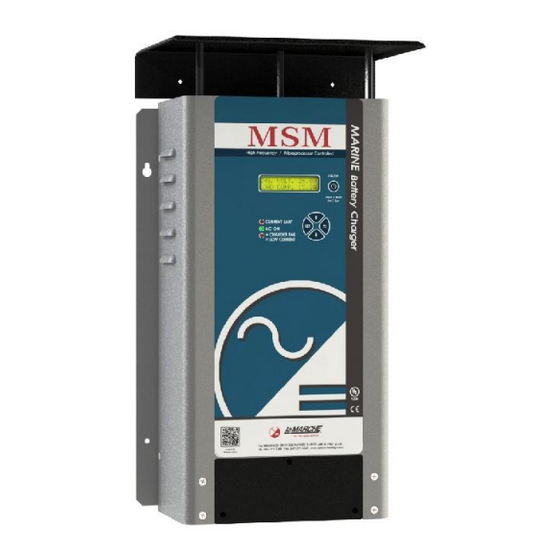
MSM
Marine High Frequency Battery Charger
106 Bradrock Dr. Des Plaines 60018-1967
Tel: 847 299 1188
Fax: 847 299 3061
V.3
Installation and Operation Manual
CPN 136069
Instruction Drawing Number: P25-LMSM-3
Revision A02
Rev. Date: 06/17
i
ECN: 21478
Advertisement
Table of Contents

Related Manuals for La Marche MSM 10-12V


Summary of Contents for La Marche MSM 10-12V
- Page 1 La Marche Manufacturing Company | www.lamarchemfg.com Marine High Frequency Battery Charger Installation and Operation Manual 106 Bradrock Dr. Des Plaines 60018-1967 Instruction Drawing Number: P25-LMSM-3 Tel: 847 299 1188 Fax: 847 299 3061 CPN 136069 Revision A02 Rev. Date: 06/17...
-
Page 2: Important Safety Instructions
Important Safety Instructions Before using this equipment read all manuals and other documents related to this unit and other equipment connected to this unit. Always have a copy of a units manual on file nearby, in a safe place; if a replacement copy of a manual is needed it can be found at the www.lamarchemfg.com. -
Page 3: Charger Location
In the unlikely event of internal damage, please inform the carrier and contact La Marche for advice on the risk due to any damage before installing the product. Verify that you have all the necessary parts per your order for proper assembly. -
Page 4: Table Of Contents
Table of Contents Important Safety Instructions ........................i Table of Contents ............................iv MSM General Description..........................1 Understanding the Model Number......................... 1 Optional Accessories Included in the Unit ...................... 1 Equipment Handling..........................2 Storing the MSM ........................... 2 Moving the MSM ........................... 2 Installation ............................ -
Page 5: Msm General Description
MSM General Description The La Marche model MSM series uses proven High Frequency charging technology that is developed specifically for Marine applications. The MSM unit incorporates power factor correction to achieve high efficiency and wide AC input range. This filtered unit is designed and built to charge VRLA, Flooded Lead Acid and Nickel Cadmium batteries. -
Page 6: Equipment Handling
Equipment Handling Storing the MSM If the MSM is to be stored for more than a few days after delivery, it should be stored within its shipping container. The location chosen for storage should be within an ambient temperature of -40 to 185° F (-40 to 85° C) with a non-condensing relative humidity of 0 to 95%. -
Page 7: Installation
Installation Mounting The MSM can be wall mounted using four #10 bolts. Install the MSM using appropriate hardware on the wall. Figure 1 - MSM Mounting Dimensions for Small Case #201 Figure 2 – MSM Mounting Dimensions for Medium Case #203... -
Page 8: Electrical Connections
Figure 3 - MSM Mounting Dimensions for Large Case #205 Electrical Connections Before beginning any work, ensure that all incoming AC supply and DC load wires are de-energized. Verify that no voltage is present by using a voltmeter at all input and output terminals. The MSM is equipped with screw- type terminals for the output connections. -
Page 9: Output Connections
2.2.2 Output Connections Built in charge divider/isolator circuitry allows up to three separate battery banks (five banks optional) to be connected to the charger. The charge divider uses one common negative connection for all batteries. The positive cable from each battery should be connected to a separate positive DC output terminal. See Figure 3 and 4. Select proper size for the DC wiring from the wire size Table 2 above. -
Page 10: Charger Fail Alarm Connections
Charger Fail Alarm Connections The Charger Fail Alarm is included with one set of Form C contacts as a standard feature on the MSM. Charger Fail LED will illuminate solid and Charger Fail contacts will De-Energize when alarm is triggered. Alarm Relay Relay Logic Contact Ratings... -
Page 11: Operation
Operation All equipment is shipped from the factory fully checked and adjusted to factory default settings. Before connecting the battery check with the battery manufacturer for the correct voltage settings and adjust the configuration accordingly (refer to section 3.3). Failure to match the charger settings with the connected battery may damage or shorten the life of the battery. -
Page 12: Led Indicators/Alarms
3.2.2 LED Indicators/Alarms LCD Display – The LCD Display shows the output DC voltage and output DC amperage at all times. Charger modes and different alarm conditions will be also be displayed if they should occur. Current Limit (Red) – The Current Limit LED will illuminate when the rectifier is operating in a current limit condition (amperage greater than unit output rating). -
Page 13: Configure Mode
Configure Mode To enter the configuration mode press the “SET” button. Once in configure mode, use the Up and Down buttons to cycle through the available options and the set button to choose the highlighted option. See the chart below for the adjustable settings in the calibration mode. -
Page 14: Setting Output Mode
3.3.1 Setting Output Mode Press SET with “CHARGING MODE” selected to change output mode. >CHARGING MODE >FLOAT MODE BATTERY TYPE EQUALIZE MODE Float charging mode is used for all normal battery charging needs. Equalize mode is used when it is necessary to equalize (or balance) the level of charge across all cells present in the battery. -
Page 15: Setting Equalize Timer
3.3.5 Setting Equalize Timer While in the “EQUALIZE MODE” menu, press SET with “EQUALIZE TIMER” selected in order to change the equalize timer. > EQUALIZE MODE >EQUALIZE TIMER EQUALIZE TIME SET CURR. LIMIT EQUALIZE CYCLE 08 Hour The Equalize Timer setting changes the amount of time that the charger remains in equalize charging cycle once activated. -
Page 16: Temperature Compensation
> THERM.DERATING > *ENABLE TEMP. COMP. DISABLE Additionally, all chargers are equipped with a thermal shutdown function; which cannot be disabled. If the ambient temperature exceeds 70°C, the DC output will shut off. LCD will display “THERMAL SHUTDOWN” and “CHARGER FAIL”. -
Page 17: Service
Service All work inside the MSM should be performed by a qualified electrician. La Marche is not responsible for any damages caused by an unqualified technician. Before working inside the MSM ensure that the AC Power is off at the main breaker box. Disconnect the battery from the charger via the battery disconnect breaker or manually disconnecting the battery cables. -
Page 18: Appendix A: Msm Specifications
Appendix A: MSM Specifications ELECTRICAL AC Input Voltage range: 102 – 264Vac Frequency Range: 45-65Hz DC Output 10 – 80A @ 12Vdc 10 – 65A @ 24 Vdc Output Filtering Suitable for Valve-Regulated batteries ± 0.5% from no load to full load over the specified input voltage, frequency and Regulation ambient temperature range. -
Page 19: Appendix B: Msm Current Draw, Heat Loss, And Case Size
Appendix B: MSM Current draw, Heat loss, and Case size AC input Current Output Draw @ 100% Load MSM Model Watts Watts Watts Case Weight BTU/Hr* Number Lost (Lbs) Fuse Amps Size 10-12V 15.0 153.2 130.2 23.0 20-12V 15.0 306.4 260.4 46.0 30-12V... -
Page 20: Appendix C: Power Cabling Guide
Appendix C: Power Cabling Guide Use the following formulas and table to determine proper wire size for minimal voltage drop. At distances exceeding 10 feet, the DC wire size should be chosen to keep the voltage difference between the units DC output terminals and the battery at less than 1/2 volt when unit is fully loaded. Table of Conventions SIZE AREA... -
Page 21: Appendix D: Manufacturer's Warranty
Should minor adjustments be required, the local La Marche sales representative should be contacted to provide this service only. All sales are final. Only standard La Marche units will be considered for return. A 25% restocking fee is charged when return is factory authorized. Special units are not returnable. -
Page 22: Appendix E: Document Control And Revision History
Appendix E: Document Control and Revision History Part Number: 136069 Instruction Number: P25-LMSM-3 Issue ECN: 21428 21428 / 4-17 21448 / 5-17 21478 / 6-17...
Need help?
Do you have a question about the MSM 10-12V and is the answer not in the manual?
Questions and answers