Table of Contents
Advertisement
Quick Links
Advertisement
Table of Contents

Related Manuals for Hexbug VEX IQ


Summary of Contents for Hexbug VEX IQ
-
Page 1: User Guide
Super Kit User Guide 228-2500-750 V.20130930... -
Page 2: Table Of Contents
Table of Contents Kit Hardware Overview: ....................3 Common part types and primary functions ................... 3 VEX IQ Kit Assembly Tips: ....................6 Removing Connector Pins ........................6 Fitting Small Gears, Pulleys, and Wheel Hubs onto Shaft ............6 Keeping the Shaft Supported & Seated in Smart Motors & Assemblies .......7 Using VEX IQ Hardware: .................... -
Page 3: Kit Hardware Overview
Kit Hardware Overview: If you can imagine it, you can build it with VEX IQ. Here’s an overview of common part types and their primary functions to help you get started. Common part types and primary functions Beams Specialty Beams... - Page 4 Shaft Shaft Bushing Shaft Lock Plates various lengths various sizes Transmit power to, or allow rotation Interfaces shafts with beams and Plates that lock onto shafts of, wheels, pulleys, gears, and plates, allowing the shaft to spin allowing design components to spin more.
- Page 5 Pulleys Rubber Belts Rubber Band Anchor various sizes various sizes Drive belts or make rollers and Use with pulleys, as a form of Use with rubber belts and bands. small wheels. stored energy, and/or as a fastener. Gears Wheel hubs and tires Smart Motor various sizes various sizes...
-
Page 6: Vex Iq Kit Assembly Tips
Fitting Small Gears, Pulleys, and Wheel Hubs onto Shaft VEX IQ shafts are built to last and run flawlessly in powered applications. Gears, pulleys, and wheel hubs fit very tightly on the VEX IQ shaft to ensure quality mechanisms with minimal amounts of “wiggle”. -
Page 7: Keeping The Shaft Supported & Seated In Smart Motors & Assemblies
Keeping the Shaft Supported & Seated in Smart Motors & Assemblies Having a motor turn a shaft in the VEX IQ system is accomplished easily with only a few parts. However, without proper shaft support and either a rubber shaft collar and/or a shaft bushing, the shaft will quickly shift or fall out of your mechanism or Smart Motor. -
Page 8: Using Vex Iq Hardware
To get yourself acquainted with the VEX IQ system, build the Clawbot from the provided instructions on the following pages. The VEX IQ Clawbot was designed to be quickly and easily assembled, and then driven around using the included Driver Control program. The claw and storage “backpack” allow you to drive around, pick up, and store a variety of small objects. -
Page 9: Vex Iq Challenge
VEX IQ robotics platform to solve an engineering challenge that is presented in the form of a game. VEX IQ Challenge teams will work together to score points in Teamwork Challenges. Teams then get to show off their robot’s skills individually in the robot and autonomous Skills Challenges. -
Page 10: Clawbot Instructions
Clawbot Instructions Part 1 Base Actual Size Step 1... - Page 11 Actual Size Step 2...
- Page 12 Actual Size Step 3...
- Page 13 Actual Size From Step 3 From Step 2 Step 4...
- Page 14 Actual Size Step 5 Actual Size Step 6...
- Page 15 Actual Size From Step 1 From Step 5 From Step 6 From Step 4 Step 7...
- Page 16 From Step 7 Step 8 Not Actual Size...
- Page 17 Actual Size Step 9...
- Page 18 Actual Size Step 10...
- Page 19 Actual Size Step 11...
- Page 20 Actual Size From Step 11 From Step 10 Step 12...
- Page 21 Actual Size Step 13 Actual Size Step 14...
- Page 22 Actual Size From Step 9 From Step 13 From Step 12 From Step 14 Step 15...
- Page 23 From Step 15 Not Actual Size Step 16...
- Page 24 Actual Size Step 17...
- Page 25 Actual Size Step 18...
- Page 26 Actual Size From Step 18 From Step 17 Step 19...
- Page 27 Plug into Port 6 Plug into Port 1 Port 1 Port 6 Step 20 Refer to pages 85 through 111 for information on the built in Driver Control program in the Robot Brain. Robot Base is now Ready to Run! Test it before continuing the Build.
-
Page 28: Part 2 Claw
Part 2 Claw Use the 45° Angle Actual Size Step 21 Use the 30° Angle Actual Size From Step 21 Step 22... - Page 29 Use the 45° Angle Actual Size From Step 22 Step 23 Use the 30° Angle Actual Size From Step 23 Step 24...
- Page 30 Actual Size Step 25 From Step 24 Actual Size From Step 25 Step 26...
- Page 31 Use the 45° Angle Actual Size Step 27 Use the 30° Angle Actual Size From Step 27 Step 28...
- Page 32 From Step 28 Use the 45° Angle Actual Size Step 29 Use the 30° Angle Actual Size From Step 29 Step 30...
- Page 33 Actual Size Step 31 From Step 30 Actual Size From Step 31 Step 32...
- Page 34 Actual Size Step 33 Actual Size Step 34...
- Page 35 From Step 34 From Step 33 Step 35 Actual Size From Step 35 Step 36...
- Page 36 Actual Size Step 37 From Step 36 Actual Size Make Step 38 (2x)
- Page 37 From Step 38 From Step 26 From Step 37 Step 39 Actual Size From Step 39 Step 40...
- Page 38 From Step 32 Step 41 Actual Size From Step 41 Step 42...
- Page 39 Actual Size Leave Shorter for Motor Clearance Actual Size Step 43...
- Page 40 Actual Size Actual Size Step 44...
- Page 41 From Step 44 Step 45 From Step 43...
-
Page 42: Part 3 Tower
Part 3 Tower Actual Size Step 46 Actual Size Actual Size From Step 47 From Step 48 Step 47 Step 46... - Page 43 Actual Size Step 49 Actual Size Actual Size From Step Step 51 From Step 50 Step 50...
- Page 44 Step 52 Actual Size Actual Size From Step 52 Step 53...
- Page 45 Use the 60° Angle Actual Size From Step 53 Step 54...
- Page 46 Step 55 Actual Size Actual Size From Step 55 Step 56...
- Page 47 Actual Size Step 57 From Step 58 Step 58 From Step 48...
- Page 48 From Step 58 From Step 20 Step 59...
- Page 49 From Step 50 Slide onto Shaft From Step 59 Step 60 Rotate to Vertical Step 61 Attach to Chassis...
- Page 50 Actual Size Step 62 From Step 61 From Step 62 Step 63...
- Page 51 Step 64 Actual Size From Step 56 Step 65...
- Page 52 Actual Size From Step 65 Step 66 From Step 66 From Step 56 Step 67...
- Page 53 Actual Size Step 68...
- Page 54 From Step 68 Step 69...
- Page 55 From Step Use the 60° Angle Actual Size Step 70 Plug into Motor Plug Into Port 10 Not Actual Size Step 71...
- Page 56 Plug Into Motor Step 72 Not Actual Size...
- Page 57 Plug Into Port Step 73 Raise POWER/LINK Open CHARGE/GAME Claw CHARGE TETHER Lower Close Claw Robot Claw is now Ready to Run!
-
Page 58: Part 4 Ball Holder
Part 4 Ball Holder Actual Size Step 74... - Page 59 Actual Size Step 75...
- Page 60 Actual Size Step 76 Actual Size Step 77...
- Page 61 Actual Size Step 78 Actual Size Step 79...
- Page 62 Actual Size Step 80 Actual Size Step 81...
- Page 63 Actual Size Step 82 Actual Size Step 83...
- Page 64 From Step Step 84 Step 85 Step 86...
-
Page 66: Part 5 Sensors
Part 5 Sensors Gyro Actual Size Step 1... - Page 67 Step 2 From Step 1...
- Page 68 Touch LED Actual Size Step 1...
- Page 69 Actual Size From Step 1 Step 2...
- Page 70 From Step 2 Step 3 Connect Touch LED to any unused port on Robot Brain using a Smart Cable.
- Page 71 Distance Sensor Actual Size Step 1...
- Page 72 Step 2 Connect Distance Sensor to any unused port on Robot Brain using a Smart Cable.
- Page 73 Bumper Switch Actual Size Step 1 Actual Size From Step 1 Step 2...
- Page 74 Actual Size Step 3 From Step 2 Actual Size Step 4...
- Page 75 From Step 3 Connect Bumper Switch to Port 9 on Robot Brain using a Smart Cable. Step 5...
- Page 76 Color Sensor Actual Size Step 1 Actual Size Step 2...
- Page 77 Connect Color Sensor to any unused port on Robot Brain using a Smart Cable. Your Clawbot with Sensors is now ready to Run! Refer to pages 85-111 for important information about using your VEX IQ robot.
-
Page 78: Autopilot Instructions
Autopilot Instructions Actual Size From Step 20 on Page 27 Step 1... - Page 79 Actual Size Step 2...
- Page 80 Actual Size Step 3 Connect Color Sensor to any unused port on Robot Brain with a Smart Cable...
- Page 81 Actual Size Step 4 Connect Gyro Sensor to any unused port on Robot Brain with a Smart Cable...
- Page 82 Actual Size Connect Touch LED to any unused port on Robot Brain with a Smart Cable Step 5...
- Page 83 Actual Size Step 6 Connect Distance Sensor to any unused port on Robot Brain with a Smart Cable...
- Page 84 Actual Size Connect Bumper Switches to any unused ports on Robot Brain with a Smart Cable...
-
Page 85: Control System Overview
Control System Overview Radio The VEX IQ Controller and Robot Brain communicate with each other through either wireless Radio Communication or Tether Cable. VEX Controller The VEX IQ Controller is at the center of what makes VEX IQ robots fun to build and easy to use. The... -
Page 86: Robot Brain Setup
Robot Brain Setup Robot Battery Charging and Usage Items you need: • Robot Battery Charger P/N: 228-2743 • Battery Charger Power Cord appropriate for your region • Robot Battery P/N: 228-2604 See the Battery Safety information in the Appendices. Plug the Battery Charger Power Cord into Robot Battery Charger. -
Page 87: Radio Installation And Removal
Slide the Robot Battery into the Robot Brain until the latch clicks. To remove the Robot Battery, press the latch down and slide the battery out. Push Down Latch Radio Installation and Removal Items you need: • Robot Brain P/N: 228-2540 •... - Page 88 Ensure there is no battery plugged into the Robot Brain. Slide the Radio into the Radio Socket. Orient the Radio so its VEX logo is away from the LCD screen. Press it in firmly. In the event the radio needs to be removed, the Robot Battery must be removed. Press the red button on the bottom of the Robot Brain while simultaneously pulling on the top of the Radio.
-
Page 89: Vex Controller Setup
VEX Controller Setup Controller Battery Installation and Removal Items you will need: • Controller P/N: 228-2530 • Small Phillips head screwdriver • Controller Battery P/N: 228-2779 Notice: See the Appendices for Battery Safety and Disposal information Remove the battery door on the back of the Controller using a small Phillips head screwdriver. Gently install the Controller Battery, ensuring that the “+”... -
Page 90: Controller Battery Charging
Controller Battery Charging The VEX Controller Battery can only be charged while installed in the Controller. See the Battery Safety information in the Appendices. There are two ways to charge the Controller Battery: Option A: Turn off the Controller. Connect the Controller to a USB port on a PC or a USB Wall Adaptor using the USB Cable P/N: 228-2785. -
Page 91: Radio Installation And Removal
Controller Battery charging will take about 4 hours. While the Controller Battery is charging, the Charge/Game LED on the Controller will be solid red. When the Controller Battery is fully charged, the LED will change to solid green. See page 95 for detailed LED color diagram. -
Page 92: Initial Wireless Setup
Removing the Radio should rarely, if ever, be done. To remove the Radio, first remove the battery door using a Phillips head screwdriver. Pull firmly on the Radio to remove it. Initial Wireless Setup Items you will need: • Robot Brain with Radio and Robot Battery installed •... - Page 93 Turn the Robot Brain ON by pressing the Check button. The Controller will automatically link and pair to the Robot Brain. The Tether Icon will appear on the Robot Brain LCD screen. Programs Driver Control Autopilot Tether Icon. See table below for Select Settings explanation.
-
Page 94: Power On And Off
Power On and OFF Robot Brain ON: Press the Check button. VEX Controller ON: Press the Power button. Check Button POWER/LINK CHARGE/GAME “X” Button Power Button Power OFF Turning off the VEX Controller or Robot Brain will automatically turn OFF the other unit, if the units are connected wirelessly. -
Page 95: Vex Controller
VEX Controller The color of the LEDs indicates the status of the Controller. Review table below. This information is very helpful when working with the Controller. Power / Link LED Power / Link LED Color Status Solid Green VEX Controller ON - with NO Radio Link (searching) Blinking Green VEX Controller ON - with good... -
Page 96: Driver Control Program
Driver Control Program The Driver Control Program is a default program built into the Robot Brain so it can be used with the Controller without programming. It maps the Controller joysticks and buttons to control specific ports on the Robot Brain. There are three modes in the Driver Control Program: Left Stick, Right Stick, and 2 Joystick. -
Page 97: Autopilot Program
In both Left Stick and Right Stick mode, one joystick will be used to drive the robot. In Right Stick the D axis on the right joystick will be used to drive the robot forward and backward. The C axis will be used to turn the robot left and right. In Left Stick, the A axis on the left joystick will be used to drive the robot forward and backward. - Page 98 Random Mode Spiral Mode Lawnmower Mode The robot will randomly The robot will begin to explore The robot will begin to explore your room by driving by driving in a spiral with an explore your room by driving in a straight line. When it ever increasing radius.
-
Page 99: Lcd On The Robot Brain
The default explore mode is Random Mode. To change between the three different modes, a Touch LED and or Color Sensor must also be connected to the Robot Brain. Tapping the Touch LED will cycle through the available explore modes. The current explore mode will be shown by illuminating the Touch LED in red for Random Mode, blue for Spiral Mode, and green for Lawnmower Mode. -
Page 100: Start Screen And List Of Programs
Start Screen and List of Programs Programs The Programs Screen of the Robot Brain is the first screen displayed after turning on the Robot Brain, and will contain a list of all programs that have been downloaded to it. The default program is Driver Control, which allows you to use and control up to eight Smart Motors and four Sensors. -
Page 101: Program Running Screen
Program Running Screen Programs › Driver Control › Run The Driver Control program is now running on the Robot Brain; the table on Page 96 contains the default mapping between the buttons on the Controller and the Smart Ports on the Robot Brain. -
Page 102: Configure Drive Control
Configure Drive Control Programs › Driver Control › Configure To customize the Driver Control program, exit any currently running programs and select Configure from the Home Screen › Driver Control menu. Configure Control Drive Normal Motor Normal Motor Normal Motor 10 Normal Enter Exit... -
Page 103: Settings
The Settings screen is accessed by pressing the X button while on the Programs. This menu contains system wide options and information about the Robot Brain and VEX IQ Controller. The first row will either contain the text Sound On or Sound Off, depending on which option is currently set. -
Page 104: Connector Ports And Buttons
The Download port is used to program the Robot Brain using either Modkit for VEX or ROBOTC. The Download port can also be used to upgrade the firmware in the Robot Brain. vexrobotics.com/vexiq/firmware to get the VEX IQ Firmware Utility. Download Port DOWNLOAD... -
Page 105: Tether Port (Vex Controller And Robot Brain)
Controller. Smart Device Ports There are 12 Smart Device ports designed for all VEX IQ electronic accessories, including Smart Motors and Sensors. All ports function the exact same way, so any accessory can be plugged into any port. See... -
Page 106: Connecting A Smart Motor
Connecting a Smart Motor Items you will need: • Robot Brain with Radio and Robot Battery installed • VEX Controller with Radio and Controller Battery installed • Smart Motor P/N: 228-2560 • Smart Cable P/N: 228-2780 Smart Motors are used to make your robotic creations come alive with motion. The Smart Motors are connected to the Robot Brain using Smart Cables. -
Page 107: Connecting A Bumper Switch
Bumper Switches can be used to turn off a motor when pressed. All VEX IQ electronics are connected to the Robot Brain using Smart Cables. These cables come in assorted lengths. All sensors should only be connected to the Robot Brain when the power is OFF. -
Page 108: Connecting A Touch Led
Connecting a Touch LED Items you will need: • Fully assembled VEX IQ Robot such as the Standard Drive Base, Autopilot Robot, Clawbot or Clawbot with Sensors (See Page 8 for more information), Radio, and Robot Battery installed in the Robot Brain •... -
Page 109: Connecting A Distance Sensor
Connecting a Distance Sensor Items you will need: • Fully assembled VEX IQ Robot such as the Standard Drive Base, Autopilot Robot, Clawbot or Clawbot with Sensors (See Page 8 for more information), Radio, and Robot Battery installed in the Robot Brain •... -
Page 110: Connecting A Color Sensor
Connecting a Color Sensor Items you will need: • Fully assembled VEX IQ Robot such as the Standard Drive Base, Autopilot Robot, Clawbot or Clawbot with Sensors (See Page 8 for more information), Radio, and Robot Battery installed in the Robot Brain •... -
Page 111: Connecting A Gyro Sensor
Connecting a Gyro Sensor Items you will need: • Fully assembled VEX IQ Robot such as the Standard Drive Base, Autopilot Robot, Clawbot or Clawbot with Sensors (See Page 8 for more information), Radio, and Robot Battery installed in the Robot Brain •... -
Page 112: Battery Safety And Disposal
• Avoid letting children play with the battery. Adults should instruct children how to use the battery correctly during all usages. • Avoid letting children take the battery out of the VEX IQ Robot Brain (Part #228-2540) or VEX IQ Charging Dock (Part # 228-2743) so as to play with battery. -
Page 113: 228-2743 Robot Battery Charger
Robot Brain, Controller, Smart Motors, and Sensors to the latest firmware version. Getting Support For additional support, please email support@vexrobotics.com. If you would like to learn more about the VEX IQ system, please visit vexrobotics.com/vexiq/ To join our online community, please go to... -
Page 114: Appendix B Compliance Statements
Appendix B Compliance Statements FCC Compliance Statement (United States) This device complies with part 15 of the FCC Rules. Operation is subject to the following two conditions: 1. This device may not cause harmful interference, and 2. This device must accept any interference received, including interference that may cause undesired operation. -
Page 115: Industry Canada Compliance Statement
Copyright and Trademark Notice ©2013 VEX Robotics, Inc. All rights reserved. Patent(s) Pending. VEX, VEX IQ, and VEX Robotics are trademarks or service marks of Innovation First International, Inc. All other product trademarks referenced herein belong to their respective companies. -
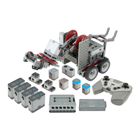
Page 116: Super Kit Inventory
Super Kit Inventory VEX IQ Super Kit 1x4 Beam 1x6 Beam 1x8 Beam 1x12 Beam (10x) (10x) (12x) (6x) 2x2 Beam 2x4 Beam 2x6 Beam 2x8 Beam (8x) (8x) (8x) (8x) 2x12 Beam 2x16 Beam 4x4 Plate 4x12 Plate (6x) - Page 117 Small Chassis Corner Connector 2x Wide, 1x2 Corner Connector 1x Wide, 1x1 Offset Corner 2x Wide, 2x1 Offset Corner (30x) (10x) Connector Connector (20x) (8x) 2x Wide, 2x1 Corner Connector 2x Wide, 1x1 Offset Corner 2x Wide, 2x2 Corner Connector 2x Wide, 1x2 Offset Corner (6x) Connector...
- Page 118 12 Tooth Gear 36 Tooth Gear 60 Tooth Gear 36 Tooth Crown Gear (10x) (10x) (6x) (4x) 30mm Rubber Belt 40mm Rubber Belt 50mm Rubber Belt 60mm Rubber Belt (2x) (2x) (2x) (2x) Inner Twist Lock Shaft Collar Outer Twist Lock Shaft Collar Controller Robot Brain (4x)
- Page 120 Expand and conquer. Once you’ve mastered the CLAWBOT, we challenge you to move onto even more advanced robot designs. Of course, all VEX mechanical gears, wheels, hardware and structural parts are cross-compatible for endless design possibilities. With hundreds more upgrade parts and accessories, the creative possibilities for your robot designs are limitless.
Need help?
Do you have a question about the VEX IQ and is the answer not in the manual?
Questions and answers