
Related Manuals for Rosemount 2700


Summary of Contents for Rosemount 2700
- Page 1 Instruction Manual PN 5102700 Model 2700 March 1999 Solu Cube Microprocessor Analyzer...
- Page 2 ELECTRICAL SHOCK HAZARD!! READ THIS PAGE BEFORE PROCEEDING! • Installation of cable connections and servicing of this Your purchase from Rosemount Analytical, Inc. has product require access to shock hazard voltage levels. resulted in one of the finest instruments available for your •...
-
Page 3: Table Of Contents
MODEL 2700 TABLE OF CONTENTS MODEL 2700 SOLU CUBE MICROPROCESSOR ANALYZER TABLE OF CONTENTS Section Title Page INSTALLATION AND QUICK START-UP ...... - Page 4 4-10 Exploded View of the Model 2700 Analyzer ......Block Diagram ..........
-
Page 5: Installation And Quick Start-Up
2. Fasten conduit connector to conduit. General. Installation must be preformed by a trained technician. NOTICE Removal of knockouts must be done with Overall dimensions of the Model 2700 Solu Cube are given in Figure 1-1. back cover in place and by striking along crease of knockout. -
Page 6: Panel Mounting
2. Install watertight conduit connectors called out in assembled to case until wiring is complete and unit has Figure 1-1. Rosemount offers these connectors in kit been inserted into cutout. To install: number 23596-00. 1. With rear cover installed, remove at least two knockouts for wire entry. -
Page 7: Wall Mounting Assembly - Wmb-5
3. Install water tight conduit connectors called out in Figure 1-1. Rosemount offers these connectors in kit number 23596-00. When rigid conduit is to be used, install fittings on the conduit first to prevent damage to the instrument case. -
Page 8: Electrical Installation
MODEL 2700 SECTION 1.0 INSTALLATION AND QUICK START-UP 1.3 ELECTRICAL INSTALLATION General. Keep sensor and power wires separated with- WARNING in the case as much as possible. Make sure power to instrument is OFF before All wiring connected to this analyzer must be rated at attempting to connect any wires inside of rear least 240 Volts. -
Page 9: Wiring To Terminal Blocks
MODEL 2700 SECTION 1.0 INSTALLATION AND QUICK START-UP Option Connections 03) are used with the Model 2700 Solu Cube, connect them directly to the analyzer via TB2, terminals 1-11 RS485 RS232 CURRENT LOOP (-21) (see Figure 1-5). The maximum cable length between a... -
Page 10: Quick Start-Up
MODEL 2700 SECTION 1.0 INSTALLATION AND QUICK START-UP DWG. NO. REV. MILLIMETER 40270008 INCH FIGURE 1-6. Junction Box and Multiple Sensor Wiring. 1.4 QUICK START-UP The following quick start-up procedures explain how to 1. Install sensor(s) as described in their instruction put the analyzer and attached sensor(s) into immediate manual, and wire to analyzer as shown in Section 1.3. -
Page 11: Summary Of Factory Settings
MODEL 2700 SECTION 1.0 INSTALLATION AND QUICK START-UP 6. If there are more sensors than can be shown on the display, MORE (F1) will be visible. Press the READING SENSORS function key F1 to show these sensors. PLEASE WAIT 7. Backlight each sensor listed and press ENTER (< ––... -
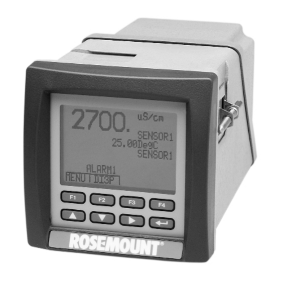
Page 12: Operation
Figure 2-1 shows the Model is pressed. 2700 Solu Cube front panel with a typical display of The Model 2700 analyzer has eight keypads on the front process data. The largest set of numerals show the of the unit. See Figure 2-1. -
Page 13: Dedicated Keypads Functions
MODEL 2700 SECTION 2.0 OPERATION Other Display Segments. 1. Alarm Annunciator fields. Shows if Alarm is active. EXIT EXIT. While in the menu mode returns the display to the Main menu display. 2. Error Annunciator field. Shows if there is an error message available. -
Page 14: Menu Tree
MODEL 2700 SECTION 2.0 OPERATION 2.5 MENU TREE The operations available and the pathways to those operations are shown in the Menu Tree in Figure 2-2 below. PROCESS DISPLAY PROCESS DISPLAY PROCESS DIS- MAIN MENU VIEW PROCESS DIS- PROCESS DIS-... -
Page 15: Examples
MODEL 2700 SECTION 2.0 OPERATION 2.6 EXAMPLES Each operation that can be accomplished on this instru- Represents one of the eight keypads. Which one is ment has been analyzed and a figure has been con- indicated by the symbol located inside. -
Page 16: General
MODEL 2700 SECTION 3.0 CALIBRATION SECTION 3.0 CALIBRATION 3.1 GENERAL 3.3 LOOP STANDARDIZATION The conductivity sensors used with this instrument have All conductivity sensors have been factory calibrated been calibrated at the factory. The analyzer reads this and do not need calibration. Displayed conductivity calibration information during start-up, and cannot value can be adjusted ±... - Page 17 MODEL 2700 SECTION 3.0 CALIBRATION Do Not attempt to standardize sensors in any other way ORP Calibration than as described in this manual. A one-point calibration may be performed on ORP pH Calibration Sensors. To calibrate an ORP sensor, first place it into the ORP Standard Solution for 15 minutes or more.
- Page 18 MODEL 2700 SECTION 3.0 CALIBRATION ORP of Saturated Quinhydrone Solutions (in Millivolts) pH 4 pH 7 Temp. °C Millivolt Potential glass containers. This solution (ferric-ferrous ammonium sulfate) will produce a nominal ORP of 476 ±20 mV at 25°C. Some tolerance in mV values is to be expected...
-
Page 19: General
MODEL 2700 SECTION 4.0 CONFIGURATION SECTION 4.0 CONFIGURATION 4.1 GENERAL This section details all of the items available in the However, the configuration worksheet included as Table Menu mode to configure the analyzer to a specific 4-1 should be completed before proceeding with any application. - Page 20 MODEL 2700 SECTION 4.0 CONFIGURATION TABLE 4-1. Factory And User Settings, continued ITEMS CHOICES RANGE DEFAULT USER SETTING Current/Voltage #1 Sensor address Any Sensor 1 - 8 Address #1 _______________ Output Type (Sec. 4.6) Current/Voltage Current** _______________ Output Range (Sec. 4.6)
-
Page 21: Configuration Procedures
MODEL 2700 SECTION 4.0 CONFIGURATION TABLE 4-1. Factory And User Settings, continued ITEMS CHOICES RANGE DEFAULT USER SETTING 2. ANALYZER (Continued) Current # 2 (only available with Option -21) Sensor address # Any Sensor 1 - 8 Address #1 _______________ Output Type (Sec. -
Page 22: Sensor Matching
MODEL 2700 SECTION 4.0 CONFIGURATION NOTE ➻ ➻ 1. Select PROGRAM Press 2. Select SENSOR If the SECURITY Code has been changed MAIN MENU –– PROGRAM from 0000, a request for security code ALARMS SENSOR OUTPUT PRIMARY DISPLAY (Figure 4-16) will appear. Follow... -
Page 23: Selecting Diff/Ratio Display Mode
MODEL 2700 SECTION 4.0 CONFIGURATION TABLE 4-2. Stored Units For Conductivity Type Sensors. SENSOR PROCESS UNITS AVAILABLE TYPE USED IN µS/cm µS/m Mohm-cm Kohm-m ppm-TDS Pure Water µS/cm R* Mohm-cm R* mS/m Mohm-m µS/cm µS/cm Mohm-cm Kohm-m µS/cm R* Water... -
Page 24: Alarms
MODEL 2700 SECTION 4.0 CONFIGURATION 4.5 ALARMS General. There are two process and one error output To Set Alarm Setpoint, Deadband Point, and relay. The process alarm relays each have their own Contacts. adjustable setpoint and deadband point that may be 1. -
Page 25: Setting Output Range
MODEL 2700 SECTION 4.0 CONFIGURATION 4.6 OUTPUTS Options installed in this instrument determine the outputs ➻ ➻ ➻ 4. With Scroll to low Range 5. Use to scroll Press available. A single current output and a RS485 non-isolat- numerals. CURRENT 1 NEXT ed serial port are standard. -
Page 26: Auto Range Feature Operation
MODEL 2700 SECTION 4.0 CONFIGURATION To Enable or Disable Auto Ranging. To Set-up Serial Port Output. This feature is only available for Output 1, and only for A non-isolated, RS485 serial port is available on the conductivity. It will work with either the Current Output basic instrument. -
Page 27: Entering Low & High Security Codes
MODEL 2700 SECTION 4.0 CONFIGURATION 4.7 SECURITY There are four kinds of security available. Entering Security Code to Access Prompts. No Security. All operations are available (View, Figure 4-16 shows how to enter either the High or Low Calibrate, and Configuration). -
Page 28: Changing Sensor Address
MODEL 2700 SECTION 4.0 CONFIGURATION 4.9 SENSOR ADDRESSING CAUTION The following procedure returns all para- meters to their default values. Check or complete Table 4-1 before starting the fol- lowing steps. To change the address assigned to individual sensors follow the steps outlined in Figure 4-18. -
Page 29: Maintenance
Refer to Figure 5-1 for an exploded view of the Solu Cube 2700 Analyzer. Table 5-1 below lists replacement parts available, part numbers, and their location on Figure 5-1. -
Page 30: Exploded View Of The Model 2700 Analyzer
Kit Bracket 23596-00 Kit, Watertight strain reliefs 175-762726 Gasket, Rear 691-898939 Assy, Terminal Block (3) 295-762722 Case 9100178 Fuse, 1 Amp 2AG 250V Slow-Blow 295-762724 Rear Cover DWG. NO. REV. 2700-01/22 FIGURE 5-1. Exploded view of the Model 2700 Analyzer... -
Page 31: Diagnostic Fault Messages
6.2 DIAGNOSTIC MESSAGES The Model 2700 Solu Cube Analyzer software diagnostics constantly monitor the input loop for possible problems. When the ERR field flashes, press F3, to display error message. These error messages will replace the Process display. - Page 32 MODEL 2700 SECTION 6.0 TROUBLESHOOTING TABLE 6-1. Diagnostic Fault Messages (Cont) Diagnostic Message Description and Suggested Actions RAM ERROR Analyzer recognizes a RAM or ROM failure. ROM ERROR • Toggle power. • If error persists, replace electronics Module. See Replacement Parts in Table 5-1.
-
Page 33: Quick Troubleshooting Guide
MODEL 2700 SECTION 6.0 TROUBLESHOOTING 6.3 TROUBLESHOOTING GUIDE Table 6-2 lists typical symptoms that may be These are not meant to be all inclusive, but to provide a encountered and suggested actions. starting point for some of the more common problems that may occur. -
Page 34: Block Diagram
Figure 6-1 is provided for reference as an overview of the electronic module functions. The Model 2700 has no operator service- able parts. It is recommended that service be performed by trained service personnel. The operator may, though, replace the electronics module sub-assembly. -
Page 35: List Of Tables
MODEL 2700 APPENDIX A APPENDIX A SOLU CUBE MODEL 2700 Section Title Page Serial Communications Protocol (Rosemount)............Overview ........................Command List ......................Data Format......................1.3.1 Read EEPROM ......................1.3.2 Read RAM ........................ 1.3.3 Reset Instrument ...................... 1.3.4 Send Base Address .................... -
Page 36: Solu Cube Model 2700 Serial Communications Protocol (Rosemount
SERIAL COMMUNICATIONS PROTOCOL OVERVIEW 3. Primary Measurment Offset = 0 RAM Address = 08AA hex The Model 2700 Solu Cube Analyzer has Solu Cube Secondary Measurement Offset = 4 Serial Communications Protocol. The user can read and RAM Address = 08AE hex write all data pertaining to process measurement and Analyzer configuration. - Page 37 MODEL 2700 APPENDIX A SERIAL COMMUNICATIONS PROTOCOL 1.3 DATA FORMAT Baud rate: 300, 1200, 2400, or 9600 Parity: NONE Byte format: One start bit, eight data bits, one stop bit Instrument Address: ADDR01 to ADDR32 (81H to A0H/129 to 160) 1.3.1 Read EEPROM...
- Page 38 MODEL 2700 APPENDIX A SERIAL COMMUNICATIONS PROTOCOL Example: Instrument Address = 1 Byte type Address 06DFH Data 03H 2700 From 2700 ‘B’ ‘#’ ‘0’ ‘6’ ‘D’ ‘F’ ‘0’ ‘3’ Example: Instrument Address = 1 Floating-point type Address 08AAH (Sensor 1 Primary Measurement) Data 2319A736 Measurement value 4.979914 x 10^-6...
- Page 39 MODEL 2700 APPENDIX A SERIAL COMMUNICATIONS PROTOCOL measurement value (-1)^0 * 2^(109-127) * 1.3054546 = 4.979914 x 10^-6 Example: Instrument Address = 1 Floating-point type Address 08AEH (Sensor 1 Secondary Measurement) Data 0000CC41H Measurement value 25.5 2700 From 2700 ‘F’...
- Page 40 MODEL 2700 APPENDIX A SERIAL COMMUNICATIONS PROTOCOL ADDR:Instrument Address CMD: Example: Instrument Address = 1 2700 1.3.4 Send Base Address 76H/118 2700 ADDR TYPE From 2700 ADDR TYPE ADDR: Instrument Address CMD: TYPE: Base address type Select Range Base Address; A3 is MSB See “Serial Communication Tables”...
- Page 41 MODEL 2700 APPENDIX A SERIAL COMMUNICATIONS PROTOCOL 2700 From 2700 ‘A’ ‘1’ ‘G’ ‘A’ ‘2’ ‘E’ ‘S’ ‘0’ ‘8’ Continued ‘0’ ‘8’ D07 D06 D05 D04 D03 D02 D01 D00 D03 DISPLAY FAILURE 1.3.6 Send Measurement 6CH/108 2700 ADDR SNRM...
- Page 42 MODEL 2700 APPENDIX A SERIAL COMMUNICATIONS PROTOCOL From 2700 ADDR SNRM SNRL A7 A6 A5 A4 A3 A2 A1 A0 Continued B7 B6 B5 B4 B3 B2 B1 B0 2700 From 2700 ‘0’ ‘0’ ‘2’ ‘3’ ‘1’ ‘9’ ‘A’ ‘7’...
- Page 43 Three scale factors sent Scale factor 0 (µS/m) is 10^8 Scale factor 1 (µS/m Raw) is 10^8 Scale factor 2 (µS/cm) is 10^6 2700 81H 77H From 2700 81H 77H 30H 33H 30H 38H 30H 38H 30H 36H ‘0’ ‘3’ ‘0’ ‘8’ ‘0’...
- Page 44 D14 spare D15 spare Example: Instrument Address = 1 Sensor1 has RTD Open Sensor4 has Electrodes Open 2700 81H 74H From 2700 81H 74H 32H 30H 45H 30H 30H 38H 30H 33H 45H ‘2’ Snr1 ‘E’ ‘0’ ‘0’ ‘8’ ‘0’...
- Page 45 “Reserved” text units are transmitted as ‘?’ ‘?’ ‘?’ ‘n’, where ‘n’ is the nth “Reserved” text unit. Example: Instrument Address = 1 Sensor Units There are 40 units for Sensors 2700 81H 78H 30H From 2700 81H 78H 30H 32H 38H 75H 53H 2FH 6DH 00H ... ‘2’ ‘8’ ‘u’ ‘S’ ‘/’ ‘m’...
- Page 46 ‘g’ ‘C’ Example: Instrument Address = 1 Dual Measurement Units There are 4 units for Dual Measurements 2700 81H 78H 31H From 2700 81H 78H 31H 30H 34H 52H 53H 54H 49H 4FH Dual ‘0’ ‘4’ ‘R’ ‘A’ ‘T’ ‘I’...
- Page 47 MODEL 2700 APPENDIX A SERIAL COMMUNICATIONS PROTOCOL TABLE 1. Commands Command name Cmd (hex) Cmd (dec) Cmd (dec) Cmd (hex) Command name Read EEPROM Update EEPROM Read RAM Read EEPROM Reset Instrument Send Measurement Send Base Address Read RAM Send Instrument Status...
- Page 48 MODEL 2700 APPENDIX A SERIAL COMMUNICATIONS PROTOCOL TABLE 2. Units and Sensor Type UNITS VALUE VALUE UNITS SENSOR TYPE µS/m %CONC VALUE TYPE µS/m Raw %SAT K.01 µS/cm DegC K1.0 µS/cm Raw K.85 Kohm-cm mS/m Kohm-cm Raw mS/m Raw Kohm-m...
- Page 49 MODEL 2700 APPENDIX A SERIAL COMMUNICATIONS PROTOCOL TABLE 3. Scale Factor Cmd 119 Cmd 119 Scale Scale TEMP. Factor Scale TEMP. Factor Scale UNITS VALUE COMP. Byte Factor VALUE UNITS COMP. Byte Factor µS/m %CONC 1E+08 µS/m Raw %SAT 1E+08 µS/cm...
- Page 50 MODEL 2700 APPENDIX A SERIAL COMMUNICATIONS PROTOCOL TABLE 3. Scale Factor (continued) DISPLAY UNITS IF DISPLAY SOURCE IS DUAL VALUE DISPLAY UNITS DIFF RATIO %PASS %REJECT SENSOR TYPE VALUE TYPE K.01 K1.0 K.85 A-16...
- Page 51 MODEL 2700 APPENDIX A SERIAL COMMUNICATIONS PROTOCOL TABLE 4. Scale Bytes from Send Scale Factors command Convert Send Measurement units to DISPLAY UNITS measurement sent in units conductivity S/cm dissolved solids dual difference S/cm dual ratio none dual %pass, %rej...
- Page 52 MODEL 2700 APPENDIX A SERIAL COMMUNICATIONS PROTOCOL TABLE 4. Scale Bytes from Send Scale Factors command (continued) Cond Scale Scale DISPLAY mult. base Factor Factor UNITS TEMP. Siemens length Byte Byte Byte COMP. (dec) (hex) Expect Kohm-m 0.001 0.01 0.00001 0.001...
- Page 53 MODEL 2700 APPENDIX A SERIAL COMMUNICATIONS PROTOCOL TABLE 5. BasesByCode Type Select Base adr Base adr Object Data Base Adr Type Code Code (hex) (dec) Sensor Primary Measurement Sensor Data 08AA 2218 Sensor Primary Measurement Sensor Data 0AA8 2728 Sensor...
- Page 54 MODEL 2700 APPENDIX A SERIAL COMMUNICATIONS PROTOCOL TABLE 6. BasesByValue Type Select Base adr Base adr Object Data Base Adr Type Code Code (hex) (dec) none none Sensor Count System 0646 1606 Sensor Type Sensor Config 0657 1623 Sensor Type...
- Page 55 MODEL 2700 APPENDIX A SERIAL COMMUNICATIONS PROTOCOL TABLE 7. BasesByName Type Select Base adr Base adr Object Data Base Adr Type Code Code (hex) (dec) Alarm Source Alarm 06DF 1759 Alarm Source Alarm 06EB 1771 none none Display Source Display...
- Page 56 MODEL 2700 APPENDIX A SERIAL COMMUNICATIONS PROTOCOL TABLE 8. AdrOffsets Offset Data Base Adr Type Data Value Bytes Alarm Source Alarm Mode Alarm Type Alarm Set Point Alarm Deadband Display Display Source Display Display Units Dual Data Dual Measurement Output...
- Page 57 MODEL 2700 APPENDIX A SERIAL COMMUNICATIONS PROTOCOL TABLE 9. AdrsByCode Type Select Offset Object Data Base Adr Type Code Code Value Bytes (hex) (dec) (dec) Sensor Primary Measurement Snr Data 08AA 2218 2221 Sensor Secondary Measurement Snr Data 2222 2225...
- Page 58 MODEL 2700 APPENDIX A SERIAL COMMUNICATIONS PROTOCOL TABLE 9. AdrsByCode (continued) Type Select Offset Object Data Base Adr Type Code Code Value Bytes (hex) (dec) (dec) Sensor Type Snr Config 06BD 1725 1725 Sensor Units Snr Config 1726 1726 Sensor...
- Page 59 MODEL 2700 APPENDIX A SERIAL COMMUNICATIONS PROTOCOL TABLE 9. AdrsByCode (continued) Type Select Offset Object Data Base Adr Type Code Code Value Bytes (hex) (dec) (dec) Alarm Set Point Alarm 1775 1778 Alarm Deadband Alarm 1779 1782 none Display Source...
- Page 60 MODEL 2700 APPENDIX A SERIAL COMMUNICATIONS PROTOCOL TABLE 10. AdrsByValue Type Select Offset Object Data Base Adr Type Code Code Value Bytes (hex) (dec) (dec) none Sensor Count System 0646 1606 1606 none Option Card System 1607 1607 Analyzer n/a...
- Page 61 MODEL 2700 APPENDIX A SERIAL COMMUNICATIONS PROTOCOL TABLE 10. AdrsByValue (continued) Type Select Offset Object Data Base Adr Type Code Code Value Bytes (hex) (dec) (dec) Sensor Serial Number LSB Snr Config 1746 1746 Alarm Source Alarm 06DF 1759 1759...
- Page 62 MODEL 2700 APPENDIX A SERIAL COMMUNICATIONS PROTOCOL TABLE 10. AdrsByValue (continued) Type Select Offset Object Data Base Adr Type Code Code Value Bytes (hex) (dec) (dec) Sensor Primary Measurement Snr Data 0CA6 3238 3241 Sensor Secondary Measurement Snr Data 3242...
- Page 63 MODEL 2700 APPENDIX A SERIAL COMMUNICATIONS PROTOCOL TABLE 11. AdrsByBase Type Select Offset Object Data Base Adr Type Code Code Value Bytes (hex) (dec) (dec) Alarm Source Alarm 06DF 1759 1759 Alarm Mode Alarm 1761 1761 Alarm Type Alarm 1762...
- Page 64 MODEL 2700 APPENDIX A SERIAL COMMUNICATIONS PROTOCOL TABLE 11. AdrsByBase (continued) Type Select Offset Object Data Base Adr Type Code Code Value Bytes (hex) (dec) (dec) Sensor Type Snr Config 0668 1640 1640 Sensor Units Snr Config 1641 1641 Sensor...
- Page 65 MODEL 2700 APPENDIX A SERIAL COMMUNICATIONS PROTOCOL TABLE 11. AdrsByBase (continued) Type Select Offset Object Data Base Adr Type Code Code Value Bytes (hex) (dec) (dec) Sensor Secondary Measurement Snr Data 12A4 4772 4775 Sensor Primary Measurement Snr Data 149E...
- Page 66 MODEL 2700 APPENDIX A SERIAL COMMUNICATIONS PROTOCOL TABLE 12. Lexicon type meaning / ASCII type meaning / ASCII data “m” delimiter command Read RAM delimiter command / data Write RAM / “o” delimiter “#” data “p” data “%” command Reset Instrument data “-”...
- Page 67 SOLU CUBE MODEL 2700 MODBUS PROTOCOL 2.1 OVERVIEW The Model 2700 Solu Cube Analyzer with Modbus capability communicates as a slave device with a Modbus-compati- ble host controller in a multidrop network. The Solu Cube hardware interface can be EIA485 non-isolated, EIA485 iso- lated, or EIA232 isolated.
- Page 68 MODEL 2700 APPENDIX A MODBUS PROTOCOL 2.3 REGISTER DESCRIPTION Each register has sixteen bits, D15 to D00. D15 is the Most Significant Bit. The following registers can be accessed as discrete outputs using Function Code 01 Read Coil Status: Alarm Status...
- Page 69 MODEL 2700 APPENDIX A MODBUS PROTOCOL Error Codes for Sensors 21-28 Bit contents 1 - Error active 0 - Error not active Register Sensor For all sensors D00 SENSOR FAILURE D01 SENSOR TIMEOUT D02 REC PARITY ERROR D03 ECHO ERROR...
- Page 70 MODEL 2700 APPENDIX A MODBUS PROTOCOL Measurement Units, Sensor Type 33-50 Register contents = 16*Unit_Value + Sensor_Type_Value See Modbus Tables for Unit_Value and Sensor_Type_Value. For Units and Sensor Type of Primary measurement Register = 33 + 2*(Sensor_number - 1) For Units and Sensor Type of Secondary measurement...
- Page 71 MODEL 2700 APPENDIX A MODBUS PROTOCOL measurement unit of measure Conductivity S/cm Dissolved solids ppm-TDS Dual Difference S/cm Dual Ratio none Dual %Pass, %Reject Resistivity ohm-cm Temperature °C Example: Read Primary measurement of Sensor1 Sensor_number = 1 First Register = 51 + 4*(Sensor_number - 1) = 51...
- Page 72 MODEL 2700 APPENDIX A MODBUS PROTOCOL Dual measurement Register = 17 - Measurement values are in Integer format, unsigned. - Negative values are in two’s complement. - Measurements on the Solu Cube display are truncated to form measurements in Integer format.
- Page 73 MODEL 2700 APPENDIX A MODBUS PROTOCOL TABLE 13. Data Data Register Format Alarm Status Integer Analog Output1 Integer Analog Output2 Integer Analog Outputs Integer Error Code for Analyzer Integer Error Code for Sensor1 Integer Error Code for Sensor2 Integer Error Code for Sensor3...
- Page 74 MODEL 2700 APPENDIX A MODBUS PROTOCOL TABLE 13. Data (continued) Data Register Format Measurement for Sensor5 - Primary Floating-Point Measurement for Sensor5 - Primary Integer Measurement for Sensor5 - Secondary Floating-Point Measurement for Sensor5 - Secondary Floating-Point Measurement for Sensor5 - Secondary...
- Page 75 MODEL 2700 APPENDIX A MODBUS PROTOCOL TABLE 14. Register Register Format Data Integer Measurement for Sensor1 - Primary Integer Measurement for Sensor1 - Secondary Integer Measurement for Sensor2 - Primary Integer Measurement for Sensor2 - Secondary Integer Measurement for Sensor3 - Primary...
- Page 76 MODEL 2700 APPENDIX A MODBUS PROTOCOL TABLE 14. Register (continued) Register Format Data Integer Units for Primary Measurement and Type for Sensor6 Integer Units for Secondary Measurement and Type for Sensor6 Integer Units for Primary Measurement and Type for Sensor7...
- Page 77 MODEL 2700 APPENDIX A MODBUS PROTOCOL TABLE 15. ErrorCodes Error Code for Analyzer SENSOR DRIVER FAILURE STD RS485 FAILURE EEPROM FAILURE DISPLAY FAILURE RAM FAILURE ROM FAILURE ERROR NO SENSORS DETECTED BUS CONTENTION FAULT Error Code for All Sensors SENSOR FAILURE...
- Page 78 MODEL 2700 APPENDIX A MODBUS PROTOCOL TABLE 16. IntegerRes .01/cm UNITS RANGE RESOLUTION Kohm-m .1-1000.0 Mohm-cm .01-100.00 0.01 Mohm-cm R .01-100.00 0.01 Mohm-m .0001-1.0000 0.0001 mS/m .001-10.000 0.001 ppm-TDS 0-999.9 µS/cm .01-100.00 0.01 µS/cm R .01-100.00 0.01 µS/m “1-10,000” 1.0/cm Kohm-cm .1-1000.0...
- Page 79 MODEL 2700 APPENDIX A MODBUS PROTOCOL TABLE 17. Unit UNITS VALUE TEMPERATURE VALUE UNITS TEMPERATURE COMPENSATED COMPENSATED µS/m %CONC µS/m Raw DegC µS/cm Kohm-cm µS/cm Raw Kohm-cm Raw Kohm-m mS/m Kohm-m Raw mS/m Raw Mohm-cm mS/cm Mohm-cm Raw mS/cm Raw...
- Page 80 MODEL 2700 APPENDIX A MODBUS PROTOCOL 2.4 MODBUS TROUBLESHOOTING GUIDE Check Connection between Master and Solu Cube o EIA232: Solu Cube Receive to Master Transmit In most cases, if the Solu Cube communicates with a Solu Cube Transmit to Master Receive Master device at all, it will communicate correctly.
-
Page 81: Sales And Part Ordering Information
• on the main display. Whenever the fault relay activates, Rosemount Analytical’s Model 2700 Solu Cube is an error key also flashes on the main display, and acti- designed for multiparameter measurement in liquid ana- vating the soft key indicated, provides a complete diag- lytical applications. -
Page 82: Electrical Specifications
MODEL 2700 APPENDIX B SALES AND PART ORDERING INFORMATION Dual Alarms RFI/EMI: Dual Alarms are standard on the Solu Cube. The set- EN50081-2 point for each alarm is independently adjustable over EN50082-2 the full range of measurement. The relays operate either... -
Page 83: Mounting Options
MODEL 2700 APPENDIX B SALES AND PART ORDERING INFORMATION 1.6 MOUNTING OPTIONS Flush Panel Mounting - Standard Wall Mounting - Optional The Solu Cube comes with adjustable brackets that allow The Solu Cube can be wall mounted using an optional the instrument to be flush panel mounted, as received. - Page 84 MODEL 2700 APPENDIX B SALES AND PART ORDERING INFORMATION 1.9 RETURN OF MATERIAL General. To expedite the repair and return of instru- 5. Send the package prepaid to: ments, proper communication between the customer Rosemount Analytical Inc. and the factory is important. A return material authoriza- Uniloc Division tion number is required.
-
Page 85: Troubleshooting Guide
MODEL 2700 APPENDIX C TROUBLESHOOTING GUIDE SOLU CUBE SYSTEM MODEL 2700 ANALYZER AND MODEL 2701 SENSOR TROUBLESHOOTING GUIDE 1.3 START-UP TEST In a Solu Cube system, communication between the analyzer and the sensors is digital. This is different from There are six steps in Start-Up: all other Uniloc analyzer-sensor systems, but in many 1. - Page 86 MODEL 2700 APPENDIX C TROUBLESHOOTING GUIDE If the customer has a working sensor, measuring those Connection check voltages is a good reference. • For three or more sensors The listed voltages for WHT and BLU are typical. See if the good sensors are all connected to one Voltages outside the ranges specified do not necessari- “main”...
- Page 87 MODEL 2700 APPENDIX C TROUBLESHOOTING GUIDE Power down the Analyzer. With the good sensor in The customer will lose any analyzer settings that are place, attach the “bad” sensor also. Power up the different from the Factory Settings. Analyzer. After about 40 seconds, the READING SEN- The F1/F3 keypress loads data from program memory SORS message will appear.
- Page 88 MODEL 2700 APPENDIX C TROUBLESHOOTING GUIDE TOP VIEW OF ELECTRONICS MODULE *- - - - - - 2 - -* *- - - - - - 4 - -* *- - - - - - 6 - -* * ETC...
- Page 89 PRODUCT, SAMPLE OR MATERIAL THAT HAVE BEEN EXPOSED TO OR USED IN AN ENVIRONMENT OR PROCESS THAT CONTAINS A HAZARDOUS MATERIAL ANY OF THE ABOVE THAT IS SUBMITTED TO ROSEMOUNT ANALYTICAL WITHOUT THE MSDS WILL BE RETURNED TO SENDER C.O.D. FOR THE SAFETY AND HEALTH OF OUR EMPLOYEES.
- Page 90 The Rosemount customer sales and service organization comprises a network of fully equipped support centers strategically located throughout the world. From many of these locations, the Rosemount Group provides support, distribution of finished products, repair facilities, and training for our customers.
- Page 91 FOLD ALONG DOTTED LINES...
- Page 92 For Customer Support Mike Stoessl 24 hours a day/365 days a year, President, Rosemount Analytical-Uniloc Division Call 1-800-854-8257 Complete this registration, fold it in thirds so the return address shows, and drop it in any mailbox, or visit our website at www.RAuniloc.com and register on-line to double your standard warranty from 1 year to 2 years.
- Page 93 EXPRESS AND IMPLIED WARRANTIES OF MERCHANTABILITY AND FITNESS FOR A PARTICULAR PURPOSE. RETURN OF MATERIAL Material returned for repair, whether in or out of warranty, should be shipped prepaid to: Rosemount Analytical Inc. Uniloc Division 2400 Barranca Parkway Irvine, CA 92606...
- Page 94 CUSTOMER SUPPORT CENTER 1-800-854-8257 ON-LINE ORDERING NOW AVAILABLE ON OUR WEB SITE http://www.RAuniloc.com Credit Cards for U.S. Purchases Only. Rosemount Analytical Inc. Uniloc Division 2400 Barranca Parkway Irvine, CA 92606 USA Tel: (949) 863-1181 http://www.RAuniloc.com © Rosemount Analytical Inc. 1998...
Need help?
Do you have a question about the 2700 and is the answer not in the manual?
Questions and answers