Table of Contents
Advertisement
Quick Links
Reference Manual
00809-0100-4809, Rev DA
September 2015
®
®
The Rosemount
Annubar
Flowmeter Series
Rosemount 585 Severe
Service Annubar Primary
Rosemount 2051CFA
Element
Rosemount 3051SFA
Annubar Flowmeter
Annubar Flowmeter
Rosemount 485
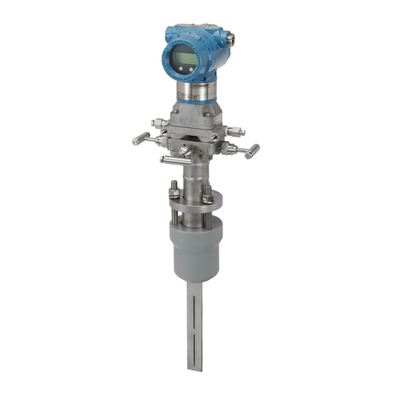
Rosemount 3051SFC_A
Annubar Primary
Rosemount 3051CFA
Compact Annubar
Element
Annubar Flowmeter
Flowmeter
Advertisement
Table of Contents


Need help?
Do you have a question about the 3051SFC_A and is the answer not in the manual?
Questions and answers