
Related Manuals for Rosemount 5081-P


Summary of Contents for Rosemount 5081-P
- Page 1 Instruction Manual LIQ-MAN-5081P/rev.J January 2015 Model 5081-P Two-Wire pH/ORP Transmitter...
- Page 2 The following instructions must be adhered to and integrated into your safety program when installing, using, and maintaining Rosemount Analytical products. Failure to follow the proper instructions may cause any one of the following situations to occur: Loss of life;...
-
Page 3: Table Of Contents
INSTALLATION ...................... unpacking and Inspection..................Pre-Installation Set up ..................... Orienting the display Board ..................Mechanical Installation..................... Power Supply/Current Loop Wiring for Model 5081-P-HT ........Power Supply Wiring for Model 5081-P-FF ............. wIRING ........................General Information ....................Wiring diagrams ...................... INTRINSICALLy SAFE AND ExPLOSION PROOF INSTALLATIONS .... - Page 4 MODEL 5081-P pH/ORP TABLE OF CONTENTS TABLE OF CONTENTS CONT’D CALIBRATION OF pH MEASUREMENTS ............. General ........................Entering and Leaving the Calibrate Menu..............using the Hold Function................... Temperature Calibration................... Auto Calibration ....................... Manual Calibration ....................Making the Transmitter Reading Match a Second pH Meter (Standardization)..
- Page 5 MODEL 5081-P pH/ORP TABLE OF CONTENTS TABLE OF CONTENTS CONT’D 12.0 TROUBLESHOOTING ................... 12.1 Warning and Fault Messages .................. 12.2 Calibration Errors ..................... 12.3 Troubleshooting - General ..................12.4 Troubleshooting When a diagnostic Message is Showing ........12.5 Troubleshooting When No diagnostic Message is Showing........
- Page 6 HART Communicator ....................AMS Main Menu Tools ..................... Mounting the Model 5081-P pH/ORP Transmitter on a Flat Surface......using the Pipe Mounting Kit to Attach the Model 5081-P pH/ORP to a pipe.... Load/Power Supply Wiring ..................Model 5081-P-HT Power Wiring details..............
- Page 7 Connection to the Model 5081-P pH/ORP Transmitter..........3-21 Preparation of Raw Connecting Cable ..............Model 5081-P-HT Infrared Remote Control — CSA, FM, & ATEX approvals ..Model 5081-P-FF Infrared Remote Control — CSA, FM, & ATEX approvals... FM Explosion-Proof Installation for Model 5081-P-HT ..........
- Page 8 Values of Standard Buffer Solutions and the Temperature Range over which pH Values are defined ..................... pH Values of Commercial (technical) Buffers and the Temperature Range over which pH Values are defined .................. Standard and Technical Buffers Recognized by the Model 5081-P pH Transmitter 10-1 ORP Settings List ....................11-1 Replacement Parts for Model 5081-P pH Transmitter ..........
-
Page 9: Description And Specifications
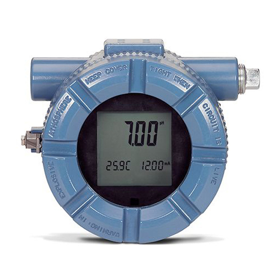
5081 is compatible with most Rosemount Analytical sen- from as far away as six feet. sors. See the Specifications section for details. The Model 5081-P Transmitter with the appropriate sensor The transmitter has a rugged, weatherproof, corrosion- can be configured for either pH or ORP (oxidation reduc- resistant enclosure (Type 4X and IP65) of epoxy-painted tion potential) measurement of aqueous solutions. -
Page 10: Specifications
The integral Minimum power supply voltage is 12 Vdc. Maximum preamplifier of the Model 5081-P may be used when power supply voltage is 42.4 Vdc (30 Vdc for intrinsically the sensor to transmitter distance is less than 15 ft safe operation). -
Page 11: Hazardous Location Approval
MODEL 5081-P pH/ORP SECTION 1.0 DESCRIPTION AND SPECIFICATIONS Accuracy: ± 1 mV @ 25°C ± 0.01 pH Repeatability: ± 1 mV @ 25°C ± 0.01 pH Stability: 0.25% / year @ 25°C Diagnostics: The internal diagnostics can detect: Calibration Error... -
Page 12: Transmitter Display During Calibration And Programming
MODEL 5081-P pH/ORP SECTION 1.0 DESCRIPTION AND SPECIFICATIONS 1.4 TRANSMITTER DISPLAy DURING CALIBRATION AND PROGRAMMING (FIGURE 1-1) 1. Continuous display of pH, ORP, conductivity, oxygen, chlorine, or ozone reading. 2. units: pH, mV, µS/cm, mS/cm, ppm, ppb, % saturation, or %. -
Page 13: Foundation Fieldbus
OUNDATION Figure 1-3 shows a 5081-P-FF being used to measure and control pH and chlorine levels in drinking water. The figure also shows three ways in which Fieldbus communication can be used to read process variables and configure the transmitter. -
Page 14: Hart Communications
HART transmitter. Either a hand-held communicator, such as the Rosemount Model 375, or a computer can be used. HART interface devices operate from any wiring termination point in the 4 - 20 mA loop. A minimum load of 250 ohms must be present between the transmitter and the power supply. -
Page 15: Asset Management Solutions
5081-P transmitter. Although AMS allows access to the basic functions of any HART compatible device, Rosemount Analytical has developed additional software for that allows access to all features of the Model 5081-P transmitter. AMS can play a central role in plant quality assurance and quality control. using AMS Audit Trail, plant operators can track calibration frequency and results as well as warnings and diagnostic messages. -
Page 16: Ams Main Menu Tools
MODEL 5081-P pH/ORP SECTION 1.0 DESCRIPTION AND SPECIFICATIONS FIGURE 1-5. AMS MAIN MENU TOOLS... -
Page 17: Installation
2.2.1 Temperature Element The Model 5081-P pH/ORP transmitter is compatible with sensors having Pt 100 and Pt 1000. Sensors from other manu- facturers may have a Pt 1000 RTd. For Rosemount Analytical sensors, the type of temperature element in the sensor is printed on the tag attached to the sensor cable. - Page 18 Junction boxes can be attached to the sensor or installed some distance away. If the junction box is not attached to the sensor, it is called a remote junction box. In most junction boxes used with the Model 5081-P pH/ORP, a flat, black plastic box attached to the same circuit board as the terminal strips houses the preamplifier.
-
Page 19: Orienting The Display Board
MODEL 5081-P pH/ORP SECTION 2.0 INSTALLATION 2.3 ORIENTING THE DISPLAy BOARD The display board can be rotated 90 degrees, clockwise or counterclockwise, from the original position. To reposition the display: 1. Loosen the cover lock nut until the tab disengages from the circuit end cap. unscrew the cap. -
Page 20: Mounting The Model 5081-P Ph/Orp Transmitter On A Flat Surface
MODEL 5081-P pH/ORP SECTION 2.0 INSTALLATION 2.4.2 Mounting on a Flat Surface. See Figure 2-1. MILLIMETER INCH FIGURE 2-1. Mounting the Model 5081-P pH/ORP Transmitter on a Flat Surface... - Page 21 See Figure 2-2. The pipe mounting kit (PN 2002577) accommodates 1-1/2 to 2 in. pipe. MILLIMETER INCH dWG. NO. REV. 40308104 dWG. NO. REV. 40308103 FIGURE 2-2. Using the Pipe Mounting Kit to Attach the Model 5081-P pH/ORP Transmitter to a Pipe...
-
Page 22: Power Supply/Current Loop Wiring For Model 5081-P-Ht
TB-14 and TB-15. A 1 mA cur- rent in this loop signifies a sensor fault. See Figure 4-3 for wiring instructions. See Section 8.4 or 10.6 and Section 12.0 for more information about sensor faults. FIGURE 2-4. Model 5081-P-HT Power wiring Details... -
Page 23: Power Supply Wiring For Model 5081-P-Ff
AC power lines or with relay actu- ated signal cables. Keep power supply/signal wiring at FIGURE 2-5. Typical Fieldbus Network Electrical least 6 ft (2 m) away from heavy electrical equipment. wiring Configuration FIGURE 2-6. Model 5081-P-FF Power wiring Details... -
Page 24: Wiring
General Information wiring Diagrams 3.1 GENERAL INFORMATION pH and ORP sensors manufactured by Rosemount Analytical can be wired to the Model 5081-P pH/ORP transmitter in three ways: 1. directly to the transmitter, 2. to a sensor-mounted junction box and then to the transmitter, 3. -
Page 25: Wiring Diagrams
Pt 100 Figure 3-10 Figure 3-12 * Sensors have a BNC connector that the Model 5081-P pH/ORP transmitter does not accept. Cut off the BNC and terminate the coaxial cable as shown in Figure 3-23. Alternatively, use a BNC adapter. -
Page 26: Wiring Diagrams For Model 396P Sensors
Figure 3-7 Figure 3-9 * Sensors have a BNC connector that the Model 5081-P pH/ORP transmitter does not accept. Cut off the BNC and terminate the coaxial cable as shown in Figure 3-23. Alternatively, use a BNC adapter (PN 9120531). -
Page 27: Wiring Diagrams For Model 385+ Sensors
Pt 100 Figure 3-19 * Sensors have a BNC connector that the Model 5081-P pH/ORP transmitter does not accept. Cut off the BNC and terminate the coaxial cable as shown in Figure 3-23. Alternatively, use a BNC adapter (PN 9120531). -
Page 28: Wire Functions For Models 399-02, 399-09, 381Ph-30-41, And 381Phe-31-41 Before Removing Bnc And Terminating Cable
MODEL 5081-P pH/ORP SECTION 3.0 wIRING REMOVE BNC ANd TERMINATE COAXIAL CABLE BEFORE WIRING SENSOR TO TRANSMITTER. SEE FIGuRE 3-23. ALTERNATIVELY, uSE A BNC AdAPTER (PN 9120531) OR ORdER MOdEL OPTION -62 (SENSOR WITH BNC REMOVEd ANd TER- MINATIONS COMPATIBLE WITH 5081 pH/ORP). IF uSING A BNC AdAPTER, THE REd WIRE IS MV OR pH IN ANd THE BLACK WIRE IS REFERENCE IN. -
Page 29: Wire Functions For Models 397-50, 397-54, 396-50, 396-54, 396R-50-60, 396R-54-60
MODEL 5081-P pH/ORP SECTION 3.0 wIRING REMOVE BNC ANd TERMINATE COAXIAL CABLE BEFORE WIRING SENSOR TO TRANSMITTER. SEE FIGuRE 3-20. ALTERNATIVELY, uSE A BNC AdAPTER (PN 9120531) OR ORdER MOdEL OPTION -62 (SENSOR WITH BNC REMOVEd ANd TERMINATIONS COMPATIBLE WITH 5081 pH/ORP). IF uSING A BNC AdAPTER, THE REd WIRE IS MV OR pH IN ANd THE BLACK WIRE IS REFERENCE IN. -
Page 30: Wiring Diagram For Models 396R-50, 396R-54, 396R-54-61, 396P-02-50, 396P-02-54
MODEL 5081-P pH/ORP SECTION 3.0 wIRING FIGURE 3-10. wire functions for Models 396R-50, 396R-54, 396R-54-61, 396P-02-50, 396P-02-54, 396P-02-55, 385+ -04, and 385+ -41-52. dWG. NO. REV. 405081P24 FIGURE 3-12. wiring diagram for Models 396R-50, 396R-54, 396R-54-61, 396P-02-50, 396P-02-54, 396P-02-55, 385+ -04, and 385+ -41-52. -
Page 31: Wire Functions For Models 396P-01-55, 385+-03, 381+-40-55, And 381+-43-55
MODEL 5081-P pH/ORP SECTION 3.0 wIRING FIGURE 3-13. wire functions for Models 396P-01-55, 385+ -03, 381+ -40-55, and 381+ -43-55. dWG. NO. REV. 405081P17 FIGURE 3-14. wiring diagram for Models 396P-01-55, 385+ -03, 381+ -40-55, and 381+ -43-55. -
Page 32: Wire Functions For Model 328A-07
MODEL 5081-P pH/ORP SECTION 3.0 wIRING dWG. NO. REV. 405081P20 FIGURE 3-15. wire functions for Model 328A-07. dWG. NO. REV. 405081P20 FIGURE 3-16. wiring diagram for Models 328A and 382+-02. dWG. NO. REV. 45081P25 FIGURE 3-17. wiring diagram for Model 385+-02. -
Page 33: Wiring Diagram For Model 320Hp-10-55
MODEL 5081-P pH/ORP SECTION 3.0 wIRING dWG. NO. REV. dWG. NO. REV. 405081P21 405081P15 FIGURE 3-18. wiring diagram for Model 320HP-10-55. FIGURE 3-19 wiring diagram for Model 320HP-10-58. - Page 34 MODEL 5081-P pH/ORP SECTION 3.0 wIRING FIGURE 3-20. Procedure for Removing BNC Connector and Preparing Coaxial Cable...
-
Page 35: Preparation Of Raw Connecting Cable
MODEL 5081-P pH/ORP SECTION 3.0 wIRING FIGURE 3-21. Preparation of Raw Connecting Cable (PN 9200273). - Page 36 MODEL 5081-P pH/ORP SECTION 3.0 wIRING...
- Page 37 MODEL 5081-P pH/ORP SECTION 3.0 wIRING...
- Page 38 MODEL 5081-P pH/ORP SECTION 3.0 wIRING...
-
Page 39: Intrinsically Safe And Explosion Proof Installations
SECTION 4.0 INTRINSICALLy SAFE & ExPLOSION PROOF SECTION 4.0 INTRINSICALLy SAFE & ExPLOSION PROOF FIGURE 4-1. Model 5081-P-HT Infrared Remote Control — CSA, FM, & Baseefa/ATEx approvals FIGURE 4-2. Model 5081-P-FF Infrared Remote Control — CSA, FM, & Baseefa/ATEx approvals... -
Page 40: Intrinsically Safe And Explosion-Proof Installations For 5081-P-Ht
MODEL 5081-P pH/ORP SECTION 4.0 INTRINSICALLy SAFE & ExPLOSION PROOF 4.1 INTRINSICALLy SAFE AND ExPLOSION-PROOF INSTALLATIONS FOR MODEL 5081-P-HT... - Page 41 MODEL 5081-P pH/ORP SECTION 4.0 INTRINSICALLy SAFE & ExPLOSION PROOF...
- Page 42 MODEL 5081-P pH/ORP SECTION 4.0 INTRINSICALLy SAFE & ExPLOSION PROOF...
- Page 43 MODEL 5081-P pH/ORP SECTION 4.0 INTRINSICALLy SAFE & ExPLOSION PROOF...
- Page 44 MODEL 5081-P pH/ORP SECTION 4.0 INTRINSICALLy SAFE & ExPLOSION PROOF...
- Page 45 MODEL 5081-P pH/ORP SECTION 4.0 INTRINSICALLy SAFE & ExPLOSION PROOF...
- Page 46 MODEL 5081-P pH/ORP SECTION 4.0 INTRINSICALLy SAFE & ExPLOSION PROOF...
- Page 47 MODEL 5081-P pH/ORP SECTION 4.0 INTRINSICALLy SAFE & ExPLOSION PROOF...
-
Page 48: Intrinsically Safe And Explosion-Proof Installations For 5081-P-Ff
MODEL 5081-P pH/ORP SECTION 4.0 INTRINSICALLy SAFE & ExPLOSION PROOF 4.2 INTRINSICALLy SAFE AND ExPLOSION-PROOF INSTALLATIONS FOR MODEL 5081-P-FF... - Page 49 MODEL 5081-P pH/ORP SECTION 4.0 INTRINSICALLy SAFE & ExPLOSION PROOF...
- Page 50 MODEL 5081-P pH/ORP SECTION 4.0 INTRINSICALLy SAFE & ExPLOSION PROOF...
- Page 51 MODEL 5081-P pH/ORP SECTION 4.0 INTRINSICALLy SAFE & ExPLOSION PROOF...
- Page 52 MODEL 5081-P pH/ORP SECTION 4.0 INTRINSICALLy SAFE & ExPLOSION PROOF...
- Page 53 MODEL 5081-P pH/ORP SECTION 4.0 INTRINSICALLy SAFE & ExPLOSION PROOF...
- Page 54 MODEL 5081-P pH/ORP SECTION 4.0 INTRINSICALLy SAFE & ExPLOSION PROOF...
- Page 55 MODEL 5081-P pH/ORP SECTION 4.0 INTRINSICALLy SAFE & ExPLOSION PROOF...
-
Page 56: Intrinsically Safe And Explosion-Proof Installations For 5081-P-Fi
MODEL 5081-P pH/ORP SECTION 4.0 INTRINSICALLy SAFE & ExPLOSION PROOF 4.3 INTRINSICALLy SAFE AND ExPLOSION-PROOF INSTALLATIONS FOR MODEL 5081-P-FI 9241503-01... - Page 57 MODEL 5081-P pH/ORP SECTION 4.0 INTRINSICALLy SAFE & ExPLOSION PROOF 1400287...
- Page 58 MODEL 5081-P pH/ORP SECTION 4.0 INTRINSICALLy SAFE & ExPLOSION PROOF 1400287...
- Page 59 MODEL 5081-P pH/ORP SECTION 4.0 INTRINSICALLy SAFE & ExPLOSION PROOF 9241504-01...
- Page 60 MODEL 5081-P pH/ORP SECTION 4.0 INTRINSICALLy SAFE & ExPLOSION PROOF 1400288...
- Page 61 MODEL 5081-P pH/ORP SECTION 4.0 INTRINSICALLy SAFE & ExPLOSION PROOF 1400288...
- Page 62 MODEL 5081-P pH/ORP SECTION 4.0 INTRINSICALLy SAFE & ExPLOSION PROOF 9241502-01...
-
Page 63: Operation With Remote Controller
Diagnostic Messages - ORP Security 5.1 OvERvIEw This section covers basic transmitter operation and software functionality. For detailed descriptions of the func- tion blocks common to all Fieldbus devices, refer to Fisher-Rosemount Fieldbus F Function Blocks OuNdATION manual, publication number 00809-4783. -
Page 64: Displays
MODEL 5081-P pH/ORP SECTION 5.0 OPERATION wITH REMOTE CONTROLLER 5.1.1 Software Functionality. The Model 5081-P pH/ORP software is designed to permit remote testing and configuration of the transmitter using the Fisher-Rosemount deltaV Fieldbus Configuration Tool, or other OuN- dATION fieldbus compliant host. -
Page 65: Infrared Remote Controller (Irc) - Key Functions
MODEL 5081-P pH/ORP SECTION 5.0 OPERATION wITH REMOTE CONTROLLER 5.3 INFRARED REMOTE CONTROLLER (IRC) - KEy FUNCTIONS The infrared remote controller is used to calibrate and program the transmitter and to read diagnostic messages. See Figure 5-4 for a description of the function of the keys. -
Page 66: Menu Tree - Ph
Figure 5-5 shows the diagnostic fault messages for pH for Model 5081-P-HT. Figure 5-6 shows the diagnostic fault messages for pH for Model 5081-P-FF. If more than one warning or fault message has been generated, the messages appear alternately. -
Page 67: Ph Menu Tree For Model 5081-P-Ff
Snr 07.00 GFH 1500 tIME 10 COdE 000 deLtA 00.02 GWH 1000 GWL 020 MENU GFL 010 CAL 000 Sub-menu rEF LO rFH 140 PROMPT rWH 040 diag Message rWL 000 rFL 000 FIGURE 5-6. pH Menu Tree for Model 5081-P-FF... -
Page 68: Menu Tree -Orp
(Figure 5-2). The display alternates between the regular display and the diagnostic message. Figure 5-7 shows the diag- nostic fault messages for ORP for Model 5081-P-HT. Figure 5-8 shows the diagnostic fault messages for ORP for Model 5081-P-FF. If more than one warning or fault message has been generated, the messages appear alternately. -
Page 69: Orp Menu Tree For Model 5081-P-Ff
ORP LinE 60 FActOrY rOFFSt 060 tEMP C dIAG OFF OutPut Cur IMPtC OFF MENU COdE 000 rEF LO rFH 140 Sub-menu rWH 040 PROMPT rWL 000 rFL 000 diag Message FIGURE 5-8. ORP Menu Tree for Model 5081-P-FF... -
Page 70: Security
MODEL 5081-P pH/ORP SECTION 5.0 OPERATION wITH REMOTE CONTROLLER 5.8 SECURITy 5.8.1 General. use the programmable security code to protect program and calibration settings from accidentally being changed. The transmitter is shipped with the security fea- ture disabled. To program a security code, refer to Section 8.6, display units. -
Page 71: Operation With Model 375
The Model 375 or 475 Communicator is a product of Emerson Process Management, Rosemount Inc. This sec- tion contains selected information on using the Model 375 or 475 with the Rosemount Analytical Model 5081-P-HT Transmitter. For complete information on the Model 375 or 475 Communicator, see the Model 375 or 475 instruc- tion manual. -
Page 72: Operation
MODEL 5081-P pH/ORP SECTION 6.0 OPERATION wITH MODEL 375 Operation 6.3.1 Off-line and On-line Operation The Model 375 Communicator features off-line and on-line communications. On-line means the communicator is connected to the transmitter in the usual fashion. While the communicator is on line, the operator can view meas- urement data, change program settings, and read diagnostic messages. -
Page 73: P-Ht Hart / Model 375 Menu Tree
Master Reset Fault History Hold Mode Calibration Zero Main Sensor Air Calibration In-process Cal dual Range Cal ##### Adjust Temperature pH 2-Pt Cal # pH Auto Cal # Standardize pH # d/A trim FIGURE 6-2. 5081-P-HT HART/Model 375 Menu Tree... - Page 74 %saturation? [No, Yes] ### Process pressure (Note: Valid only when process pressure is enabled) Air cal pressure ## (read only) Input filter Sensor SST Sensor SSS dual Range Cal [disable, Enable] #### FIGURE 6-2. 5081-P-HT HART/Model 375 Menu Tree...
- Page 75 PV is Oxygen * SV is Temp ** TV is Snsr Cur *** 4V is pH **** Poll addr Burst option [PV, %range/current, Process vars/crnt] Burst mode [Off, On] Num req preams Num resp preams FIGURE 6-2. 5081-P-HT HART/Model 375 Menu Tree...
- Page 76 Valid when PV = Oxygen Valid when PV = Oxygen and unit = %sat #### Valid when PV = Free Cl, Ttl Cl, or Chlrmn ##### Valid when dual Range Cal = Enable FIGURE 6-2. 5081-P-HT HART/Model 375 Menu Tree...
-
Page 77: Calibration Of Ph Measurements
MODEL 5081-P pH/ORP SECTION 7.0 CALIBRATION OF pH MEASUREMENTS SECTION 7.0 CALIBRATION OF pH MEASUREMENTS General Entering and Leaving the Calibrate Menu Using the Hold Function Temperature Calibration Auto Calibration Manual Calibration Making the Transmitter Reading Match a Second pH Meter (Standardization) 7.1 GENERAL... -
Page 78: Temperature Calibration
MODEL 5081-P pH/ORP SECTION 7.0 CALIBRATION OF pH MEASUREMENTS 7.4 TEMPERATURE CALIBRATION 7.4.1 Purpose 1. As discussed in Section 13.6, Glass Electrode Slope, measuring tempera- ture is an important part of measuring pH. The accuracy of a new sensor and transmitter loop is about ±1°C, which is adequate for most applications. -
Page 79: Auto Calibration
The pH of a buffer changes with temperature. Equations relating pH to temperature for common buffers have been programmed into the Model 5081-P pH transmitter. during auto calibration, the transmitter calculates the correct buffer value and uses it in the calibration. - Page 80 MODEL 5081-P pH/ORP SECTION 7.0 CALIBRATION OF pH MEASUREMENTS NOTE A transmitter adjacent to the one being calibrated may pick up signals from the IRC. To avoid accidentally changing settings, use a different security code for each nearby transmitter. See Section 5.8, Security.
-
Page 81: Manual Calibration
The pH of a buffer changes with temperature. Equations relating pH to temperature for common buffers have been programmed into the Model 5081-P pH transmitter. during auto calibration, the transmitter calculates the correct buffer value and uses it in the calibration. during manual calibration, the user must enter the correct pH value. - Page 82 MODEL 5081-P pH/ORP SECTION 7.0 CALIBRATION OF pH MEASUREMENTS NOTE A transmitter adjacent to the one being calibrated may pick up signals from the IRC. To avoid accidentally changing settings, use a different security code for each nearby transmitter. See Section 5.8, Security.
-
Page 83: Making The Transmitter Reading Match A Second Ph Meter (Standardization)
MODEL 5081-P pH/ORP SECTION 7.0 CALIBRATION OF pH MEASUREMENTS 7.7 MAKING THE TRANSMITTER READING MATCH A SECOND pH METER (STAN- DARDIzATION). 7.7.1 Purpose 1. This section describes how to make the transmitter reading match the reading from a second pH meter. The measurement made with the second meter is called the standard pH (pH ). - Page 84 MODEL 5081-P pH/ORP SECTION 7.0 CALIBRATION OF pH MEASUREMENTS NOTE A transmitter adjacent to the one being calibrated may pick up signals from the IRC. To avoid accidentally changing settings, use a different security code for each near- by transmitter. See Section 5.8, Security.
-
Page 85: Programming For Ph Measurements
1. assign pH values to the 4 and 20 mA outputs (for Model 5081-P-HT only), 2. set the current generated by the transmitter during hold, 3. set the current generated by the transmitter when a fault is detected (for Model 5081-P-HT only), 4. change sensor diagnostic limits, 5. -
Page 86: Ph Settings List
1. Measurement type tYPE pH/ORP _______ 2. Temperature units tEMP °C/°F °C _______ 3. Output units (for 5081-P-HT only) OutPut mA/% of full scale _______ 4. Code COdE 0 to 999 _______ E. Buffer (Section 8.7) buFFEr 1. Auto Calibration Function... -
Page 87: Output Ranging
MODEL 5081-P PH/ORP SECTION 8.0 PROGRAMMING FOR pH MEASUREMENTS 8.3 OUTPUT RANGING 8.3.1 Purpose This section describes how to do the following: 1. assign pH values to the 4 and 20 mA outputs, 2. set the output current generated by the transmitter during hold, 3. -
Page 88: Diagnostic Parameters
MODEL 5081-P pH/ORP SECTION 8.0 PROGRAMMING FOR pH MEASUREMENTS 8.4 DIAGNOSTIC PARAMETERS 8.4.1 Purpose This section describes how to do the following: 1. change the standardization or reference offset, 2. enable and disable sensor diagnostics, 3. enable and disable glass impedance temperature compensation, 4. -
Page 89: Suggested Warning And Failure Limits For Low Impedance Reference Electrodes
Both high impedance and low impedance ref- erence electrodes can be used with the Model 5081-P pH/ORP transmitter. 5. WARNING ANd FAILuRE LIMITS FOR REFERENCE ELECTROdE. - Page 90 MODEL 5081-P pH/ORP SECTION 8.0 PROGRAMMING FOR pH MEASUREMENTS 8.4.3 Procedure PROGRAM 1. Press PROG on the infrared remote controller (IRC). dIAGnOSTIC 2. Press NEXT until the diAGnOStIC sub-menu appear. Press ENTER . EXIT NEXT ENTER PROGRAM 3. The screen displays the rOFFSt prompt. use the editing keys to change the flashing rOFFSt display to the desired standardization (reference) offset (in millivolts).
- Page 91 MODEL 5081-P pH/ORP SECTION 8.0 PROGRAMMING FOR pH MEASUREMENTS 12. The rFH prompt appears. use the editing keys to change the display to the desired ref- PROGRAM erence electrode high impedance fault value. The allowed ranges are 1400 EXIT NEXT...
-
Page 92: Temperature Related Settings
(and sometimes fourth) wire allows the transmitter to correct for the resistance of the lead wires and for changes in wire resistance with temperature. The Model 5081-P pH/ORP transmitter can also be used with a two-wire RTd. Select a three-wire configuration and jumper the RTd return and -RTd sense terminals (terminals 3 and 4, respectively). - Page 93 MODEL 5081-P pH/ORP SECTION 8.0 PROGRAMMING FOR pH MEASUREMENTS 8.5.3 Procedure PROGRAM tEMP 1. Press PROG on the infrared remote controller (IRC). EXIT NEXT ENTER 2. Press NEXT until the tEMP sub-menu appears in the display. Press ENTER . PROGRAM 3.
-
Page 94: Display Units
The units selected are shown in the main display next to the measured value. 2. OuTPuT CuRRENT dISPLAY (5081-P-HT only). The transmitter generates a 4 to 20 mA output signal directly proportional to the pH of the sample. The output signal appears on the same line with the temperature. -
Page 95: Buffer Calibration Parameters
Tables 8-2 and 8-3 list the buffers the Model 5081-P pH/ORP trans- mitter recognizes and the temperature range over which the buffer pH is defined. -
Page 96: Ph Values Of Commercial (Technical) Buffers And The Temperature Range Over Which Ph Values Are Defined
12.75 0 - 90 3. STABILITY CRITERIA. For the Model 5081-P pH/ORP transmitter to accept calibra- tion data, the pH must remain within a specified range for a specified period of time. The default values are 0.02 pH units and 10 seconds. In other words, at the default setting, calibration data will be accepted as soon as the pH reading is constant to within 0.02 units... -
Page 97: Isopotential Parameters
MODEL 5081-P pH/ORP SECTION 8.0 PROGRAMMING FOR pH MEASUREMENTS 8.8 ISOPOTENTIAL PARAMETERS 8.8.1 Purpose This section describes how to do the following: 1. convert the pH at the measurement temperature to the pH at a reference temperature by entering a solution temperature coefficient, 2. - Page 98 MODEL 5081-P pH/ORP SECTION 8.0 PROGRAMMING FOR pH MEASUREMENTS 8.8.3 Procedure PROGRAM 1. Press PROG on the infrared remote controller (IRC). ISOPOtntAL 2. Press NEXT until the ISOPOtntAL sub-menu appears. Press ENTER . EXIT NEXT ENTER 3. The screen displays the tCOEFF prompt. use the editing keys to change the display PROGRAM to the desired solution temperature coefficient.
-
Page 99: Generating A Test Current
MODEL 5081-P PH/ORP SECTION 8.0 PROGRAMMING FOR pH MEASUREMENTS 8.9 GENERATING A TEST CURRENT (for 5081-P-HT only) 8.9.1 Purpose This section describes how to generate output currents for testing recorders and data han- dling systems. 8.9.2 what happens while the transmitter is generating a test current? 1. -
Page 100: Calibration Of Orp Measurements
MODEL 5081-P pH/ORP SECTION 9.0 CALIBRATION OF ORP MEASUREMENTS SECTION 9.0 CALIBRATION OF ORP MEASUREMENTS General Entering and Leaving the Calibrate Menu Using the Hold Function Temperature Calibration Standardization 9.1 GENERAL The Calibrate menu allows the user to calibrate the ORP and temperature response of the sensor. -
Page 101: Temperature Calibration
MODEL 5081-P PH/ORP SECTION 9.0 CALIBRATION OF ORP MEASUREMENTS 9.4 TEMPERATURE CALIBRATION 9.4.1 Purpose 1. As discussed in Section 14.6 (ORP, Concentration, and pH), ORP is a function of temperature. The accuracy of a new sensor/transmitter loop is about ±1°C, which is adequate for most applications. A new sensor sel- dom requires temperature calibration. -
Page 102: Standardization
8-hour shelf life. Iron (II) - iron (III) standard is available from Rosemount Analytical as PN R508-16OZ. The ORP of the standard solution measured against a silver-silver chloride reference electrode is 476±20 mV at 25°C. -
Page 103: Programming For Orp Measurements
1. assign ORP values to the 4 and 20 mA outputs (for Model 5081-P-HT only), 2. set the current generated by the transmitter during hold (for Model 5081-P-HT only), 3. set the current generated by the transmitter when a fault is detected (for Model 5081-P-HT only), 4. change sensor diagnostic limits, 5. -
Page 104: Orp Settings List
1. Measurement type tYPE pH/ORP _______ 2. Temperature units tEMP °C/°F °C _______ 3. Output units (for Model 5081-P-HT only) OutPut mA/% of full scale _______ 4. Code COdE 0 to 999 _______ D. Output Simulation (Section 10.7) SIMOutPut (for Model 5081-P-HT only) 1. -
Page 105: Output Ranging
MODEL 5081-P pH/ORP SECTION 10.0 PROGRAMMING FOR ORP MEASUREMENTS 10.3 OUTPUT RANGING (For Model 5081-P-HT only) 10.3.1 Purpose This section describes how to do the following: 1. assign ORP values to the 4 and 20 mA outputs, 2. set the output current generated by the transmitter during hold, 3. - Page 106 MODEL 5081-P pH/ORP SECTION 10.0 PROGRAMMING FOR ORP MEASUREMENTS PROGRAM 10.3.3 Procedure OutPut 1. Enter the Program menu by pressing PROG on the IRC. The OutPut sub-menu EXIT NEXT ENTER appears. PROGRAM 2. Press ENTER. The screen displays the 4 MA prompt. use the editing keys to -1400 change the displayed number to the desired ORP.
-
Page 107: Temperature Element
The Model 5081-P transmitter can also be used with a two-wire RTd. Select a three-wire configuration and jumper the RTd return and -RTd sense terminals (terminals 3 and 4, respectively). -
Page 108: Display Units
Press ENTER to save. EXIT ENTER PROGRAM 5. For Model 5081-P-HT only — The screen displays the OUtPUt prompt. Press é or ê to toggle between % and CUr. Press ENTER to save. OUtPUt EXIT ENTER 6. The screen displays the COdE prompt. use the editing keys to enter a security code PROGRAM between 001 and 999. -
Page 109: Diagnostic Parameters
However, there are applications that call for either a high impedance sodium or pH glass reference electrode. Both high impedance and low impedance reference electrodes can be used with the Model 5081-P pH/ORP transmitter. WARNING ANd FAILuRE LIMITS FOR THE REFERENCE ELECTROdE. Warning tells the user that the reference electrode impedance is approaching the failure limit. - Page 110 MODEL 5081-P pH/ORP SECTION 10.0 PROGRAMMING FOR ORP MEASUREMENTS 10.6.3 Procedure PROGRAM dIAGnOSTIC 1. Press PROG on the infrared remote controller (IRC). EXIT NEXT ENTER 2. Press NEXT until the diAGnOStIC sub-menu appears. Press ENTER. PROGRAM 3. The screen displays the rOFFSt prompt. use the editing keys to change the flashing rOFFSt display to the desired standardization (reference) offset (in millivolts).
- Page 111 MODEL 5081-P pH/ORP SECTION 10.0 PROGRAMMING FOR ORP MEASUREMENTS 8. The rwH prompt appears. In the display, W appears as wj. use the editing PROGRAM keys to change the display to the desired reference electrode high impedance rWJH 0040 warning value. The allowed ranges are...
-
Page 112: Generating A Test Current
MODEL 5081-P pH/ORP SECTION 10.0 PROGRAMMING FOR ORP MEASUREMENTS 10.7 GENERATING A TEST CURRENT (for Model 5081-P-HT only) 10.7.1 Purpose This section describes how to generate output currents for testing recorders and data han- dling systems. 10.7.2 what happens while the transmitter is generating a test current? 1. -
Page 113: Maintenance
11.5 Calibration 11.1 OvERvIEw This section gives general procedures for routine maintenance of the 5081-P pH/ORP transmitter and pH and ORP sensors. The transmitter needs almost no routine maintenance. Sensors require periodic inspection and cleaning. The calibration of the transmitter-sensor combination should be checked regularly, and the loop recali- brated if necessary. -
Page 114: Ph Sensor Maintenance
Shipping weight 23992-02 For Model 5081-P-HT — PCB stack consisting of the CPu, communication, and analog 1 lb/0.5 kg boards; display board is not included; CPu, communication, and analog boards are factory-calibrated as a unit and cannot be ordered separately 23992-03 For Model 5081-P-FF —... -
Page 115: Checking The Potential Of The Reference Electrode
Refer to the wiring diagram(s) for the sensors to identify the reference leads. A laboratory silver/silver chloride reference electrode can be used in place of the second sensor. All Rosemount Analytical pH sensors have a silver/silver chloride reference, and most sensors use gelled saturated potassium chlo- ride for the fill. -
Page 116: Orp Sensor Maintenance
The platinum electrode is easily cleaned by using a tissue to rub the metal surface with a paste of baking soda (sodium bicarbonate). A clean platinum electrode is bright and shiny. 11.4.3 Checking the Reference Electrode ORP electrodes manufactured by Rosemount Analytical have a silver/silver chloride reference. Section 11.3.3 describes how to check the performance of the reference electrode. 11.5 CALIBRATION 11.5.1 General... -
Page 117: Troubleshooting
FACTORy ASSISTANCE AND REPAIRS 12.1 wARNING AND FAULT MESSAGES The Model 5081-P pH/ORP transmitter continuously monitors the measurement loop (sensor and transmitter) for conditions that cause erroneous measurements. When a problem occurs, the transmitter displays either a warning or fault mes- sage. -
Page 118: Calibration Errors
12.4 TROUBLESHOOTING wHEN A DIAGNOSTIC MESSAGE IS SHOwING The Model 5081-P pH/ORP transmitter continuously monitors the measurement loop (sensor and transmitter) for prob- lems. If a problem is detected, the transmitter displays a fault or error message. The message appears in the tempera- ture/output area of the main display. - Page 119 Pay particular attention to the following: a. For Rosemount Analytical PLuS (+) and TupH sensors with integral preamplifiers, the blue solution ground wire must be attached to TB-8 (SOL GNd) and the gray reference in wire must be attached to...
- Page 120 TB-7. c. For Rosemount Analytical PLuS (+) and TupH sensors that do not have an integral preamplifier, attach the blue solution ground wire to TB-8 or, better, leave the blue wire unattached and jumper TB-7 to TB-8.
- Page 121 MODEL 5081-P pH/ORP SECTION 12.0 TROUBLESHOOTING SLOPE STATUS OF SENSOR 54-60 mV/unit pH Sensor is in good condition. 48-50 mV/unit pH Sensor is nearing the end of its life. Once the slope drops below 48 mV/unit pH, the sensor can no longer be calibrated.
- Page 122 C. Measure and make a note of the reference impedance (rIMP). See Section 12.7. If the reference impedance is low (<70 kilohms)... a. The reference electrode is in good condition. pH sensors manufactured by Rosemount Analytical use low impedance silver/silver chloride reference electrodes.
- Page 123 MODEL 5081-P pH/ORP SECTION 12.0 TROUBLESHOOTING 12.4.4 rEFwArn rEF wArn is an electrode fault message. It means the reference electrode impedance exceeds the programmed Reference Warning High (RwH) limit. Ideally, when the measurement system exceeds the warning limits, the user will have adequate time to diagnose and correct problems before a failure occurs.
-
Page 124: Three-Wire Rtd
MODEL 5081-P pH/ORP SECTION 12.0 TROUBLESHOOTING B. Check the sensor. Refer to the wiring diagrams in Section 3.0 to identify the RTd leads. disconnect the RTd leads and measure the resistances shown in Figure 12-3. The measured resistance should agree with the value in Table 12-1 to within about 1%. -
Page 125: Temperature Simulation Into The Model 5081-P Ph/Orp Transmitter
25°C shown in Table 12-1. The measured temperature should equal 25°C to within ±1°C. FIGURE 12-4. Temperature simulation into the Model 5081-P pH/ORP transmitter. If the measured temperature is correct, the transmitter is working properly. If the measured temperature is incorrect, calibrate the transmitter against the standard resistance equivalent to 25°C. - Page 126 1. Be sure all wires between the junction box and the transmitter are connected. 2. use Rosemount Analytical cable. Generic cable may not work. Refer to Section 3.0 for part numbers. If the diagnostic message clears, the interconnecting cable was the problem.
- Page 127 MODEL 5081-P pH/ORP SECTION 12.0 TROUBLESHOOTING 12.4.9 SLOPE Err LO SLOPE Err LO means that a two-point buffer calibration attempt has failed. The slope is too low (<40 mV/pH) for a good measurement. Troubleshooting Flowchart-SLOPE Err LO A. Repeat the calibration.
- Page 128 MODEL 5081-P pH/ORP SECTION 12.0 TROUBLESHOOTING 12.4.10 SLOPE Err HI SLOPE Err HI means that a two-point buffer calibration attempt has failed. The slope is too high (>62 mV/pH) for a good measurement. Troubleshooting Flowchart-SLOPE Err HI A. Repeat the calibration.
- Page 129 MODEL 5081-P pH/ORP SECTION 12.0 TROUBLESHOOTING If the sensor is not rebuildable... Try the reference electrode rejuvenation procedure described in Section 11.0. If the rejuvenated sensor can be calibrated, the problem has been corrected. If the sensor cannot be calibrated, replace the sensor.
-
Page 130: Troubleshooting When No Diagnostic Message Is Showing
MODEL 5081-P pH/ORP SECTION 12.0 TROUBLESHOOTING 12.4.15 FACt FAIL FACt FAIL appears if the transmitter factory calibration message has been triggered. A stray noise spike can cause this message to appear. If the pH reading seems acceptable, reset the calibration flag. -
Page 131: Transmitter Does Not Respond To Remote Controller
3. Hold the IRC closer (within two feet) in case the batteries are getting weak. B. If step A fails to help, check the IRC. 1. If a second Model 5081-P transmitter is available, test the IRC on that transmitter. If a spare transmitter is not available, continue with step 2. -
Page 132: Ph Reading In Buffer Drifts During Manual Calibration
The on-line instrument is subject to process variables, for example grounding potentials, stray voltages, and orientation effects, that do not affect the laboratory or portable instrument. To make the Model 5081-P pH/ORP transmitter match the reading from a second pH meter refer to Section 7.7. - Page 133 MODEL 5081-P pH/ORP SECTION 12.0 TROUBLESHOOTING 12.5.8 Buffer Calibration Is Acceptable; Process pH is Grossly Different from Expected value. The symptoms suggest a ground loop (measurement system connected to earth ground at more than one point), a floating system (no earth ground), or noise being induced into the transmitter by sensor cabling. The problem arises from the process or installation.
-
Page 134: Hart Communications
2. The Communicator can be connected across the power terminals (TB-15 and TB-16). d. Verify that the Model 375 or 475 is working correctly by testing it on another HART Smart device. 1. If the Communicator is working, the transmitter electronics may have failed. Call Rosemount Analytical for assistance. -
Page 135: Displaying Diagnostic Variables
12.7.1 General. This section describes how to simulate a pH input into the 5081-P pH/ORP transmitter. pH is directly proportional to volt- age. To simulate the pH measurement, connect a standard millivolt source to the transmitter. If the transmitter is working properly, it will accurately measure the input voltage and convert it to pH. -
Page 136: Ph Simulation When The Preamplifier Is Located In The Transmitter
MODEL 5081-P pH/ORP SECTION 12.0 TROUBLESHOOTING 12.7.2 pH Simulation when the Preamplifier Is Located in the Transmitter. 1. Program PAMP to "transmitter". See Section 5.0. 2. Turn off sensor diagnostics. See Section 8.3. 3. Turn off automatic temperature compensation. Set manual tem- perature compensation to 25°C. -
Page 137: Simulate Ph Through Model 381+ Sensor Preamplifier
MODEL 5081-P pH/ORP SECTION 12.0 TROUBLESHOOTING 12.7.4 pH Simulation with the Model 381+ Sensor 1. Verify that switch S-1 is set to "sensor or junction box". See Section 2.2. 2. Turn off sensor diagnostics. See Section 5.5. 3. Turn off automatic temperature compensation. Set manual temperature compensation to 25°C. See Section 8.5. -
Page 138: Factory Assistance And Repairs
MODEL 5081-P pH/ORP SECTION 12.0 TROUBLESHOOTING 10. Touch the other end of the second jumper to the center pin of the BNC connector on the preamplifier. dO NOT LET THE WIRE TOuCH THE OuTSIdE OF THE BNC CONNECTOR. 11. Measure the voltage. The measured voltage should be 0 mV, and the pH should be approximately 7. Because the calibration data in the transmitter may be offsetting the input voltage, the displayed pH may not be exactly 7.0. -
Page 139: Ph Measurements
MODEL 5081-P pH/ORP SECTION 13.0 pH MEASUREMENTS SECTION 13.0 pH MEASUREMENTS 13.1 General 13.2 Measuring Electrode 13.3 Reference Electrode 13.4 Liquid Junction Potential 13.5 Converting voltage to pH 13.6 Glass Electrode Slope 13.7 Buffers and Calibration 13.8 Isopotential pH 13.9 Junction Potential Mismatch 13.10 Sensor Diagnostics... -
Page 140: Measuring Electrode
MODEL 5081-P pH/ORP SECTION 13.0 pH MEASUREMENTS designed, the liquid junction potential is usually small and rel- The overall potential of the measuring electrode equals the potential of the internal reference electrode plus the poten- atively constant. All three potentials depend on temperature. -
Page 141: Liquid Junction Potential
MODEL 5081-P pH/ORP SECTION 13.0 pH MEASUREMENTS 13.4 LIQUID JUNCTION POTENTIAL from the sample diffuse through the pores. diffusion is driv- en by concentration differences. Each ion migrates from The salt bridge (see Figure 13-4) is an integral part of the ref- where its concentration is high to where its concentration is erence electrode. -
Page 142: Glass Electrode Slope
However, over a range of two or three pH units, the slope voltage to pH is called temperature compensation. All mod- is usually close to ideal. ern process pH meters, including the Model 5081-P Calibration compensates for non-ideal behavior. Calibration pH/ORP transmitter, have automatic temperature compen- involves the use of solutions having exactly know pH, called sation. -
Page 143: Isopotential Ph
MODEL 5081-P pH/ORP SECTION 13.0 pH MEASUREMENTS are placed in pH 10 buffer, the cell voltage is V . Note that The microprocessor makes assumptions when the meas- is not 0 mV as would be expected in an ideal sensor, but urement and calibration temperatures are different. -
Page 144: Sensor Diagnostics
MODEL 5081-P pH/ORP SECTION 13.0 pH MEASUREMENTS term in equation 4 to the voltage is also shown. The liquid 13.11 SHIELDS, INSULATION, AND junction potentials in the buffers are assumed to be equal PREAMPLIFIERS and are exaggerated for clarity. pH measurement systems, cell and meter, have high If the liquid junction potential in the sample differs from the impedance. -
Page 145: Orp Measurements
MODEL 5081-P pH/ORP SECTION 14.0 ORP MEASUREMENTS SECTION 14.0 ORP MEASUREMENTS 14.1 General 14.2 Measuring Electrode 14.3 Reference Electrode 14.4 Liquid Junction Potential 14.5 Relating Cell voltage to ORP 14.6 ORP, Concentration, and pH 14.7 Interpreting ORP Measurements 14.8 Calibration 14.1 GENERAL... -
Page 146: Measuring Electrode
MODEL 5081-P pH/ORP SECTION 14.0 ORP MEASUREMENTS 14.2 MEASURING ELECTRODE 14.4 LIQUID JUNCTION POTENTIAL A salt bridge (see Figure 14-3) is an integral part of the Figure 14-2 shows a typical ORP measuring elec- reference electrode. It provides the electrical connec- trode. -
Page 147: Relating Cell Voltage To Orp
MODEL 5081-P pH/ORP SECTION 14.0 ORP MEASUREMENTS FIGURE 14-4. The Origin of Liquid Junction Potentials. The figure shows a thin section through a pore in the junction plug. The junction separates a solution of potassium chloride on the left from a solution of hydrochloric acid on the right. The solutions have equal molar concentration. Driven by con- centration differences, hydrogen ions and potassium ions diffuse in the directions shown. -
Page 148: Interpreting Orp Measurements
MODEL 5081-P pH/ORP SECTION 14.0 ORP MEASUREMENTS is described by the following equation, called the Nernst equation: 0.1987 (t + 273.15) E = E° - In the Nernst equation, E is the electrode potential and E° is the standard electrode potential, both in millivolts, t is temperature in °C, n is the number of electrons... -
Page 149: Calibration
MODEL 5081-P pH/ORP SECTION 14.0 ORP MEASUREMENTS The Nernst equation for reaction 3 is: chlorine. Although the details are beyond the scope of this discussion, the result is shown in equation 7: 0.1987 (t + 273.15) E = E°- 0.1987 (t + 273.15) - Page 150 MODEL 5081-P pH/ORP SECTION 14.0 ORP MEASUREMENTS The ORP of the iron (II) - iron (III) standard when meas- ured with a platinum electrode against a saturated sil- ver-silver chloride reference is 476 ± 20 mV at 25°C. The range of values is caused primarily by the high and variable liquid junction potential generated in solutions containing high acid concentrations.
-
Page 151: Theory - Remote Communications
HART transmitter. Either a hand-held communicator, such as the Rosemount Model 475, or a computer can be used. HART interface devices operate from any wiring termination point in the 4 - 20 mA loop. -
Page 152: Asset Management Solutions
HART-compatible device, including the Model 5081-P pH/ORP transmitter. Although AMS allows access to the basic functions of any HART compatible device, Rosemount Analytical has developed additional software for that allows access to all features of the Model 5081-P pH/ORP transmitter. -
Page 153: Return Of Material
Call 1-949-757-8500 for a R e tu r n Call Rosemount Analytical for authorization. Materials Authorization (RMA) number. Supply the purchase order number, and make sure to provide the name and telephone number 16.2 wARRANTy REPAIR. - Page 155 EXPRESS ANd IMPLIEd WARRANTIES OF MERCHANTABILITY ANd FITNESS FOR A PARTICuLAR PuRPOSE. RETURN OF MATERIAL Material returned for repair, whether in or out of warranty, should be shipped prepaid to: Emerson Process Management Rosemount Analytical 2400 Barranca Parkway Irvine, CA 92606 The shipping container should be marked:...
- Page 156 Emerson Process Management ©2015 Rosemount Analytical, Inc. All rights reserved. The Emerson logo is a trademark and service mark of Emerson Electric Co. Brand name is a mark 2400 Barranca Parkway of one of the Emerson Process Management family of companies. All other marks are the property Irvine, CA 92606 USA of their respective owners.
Need help?
Do you have a question about the 5081-P and is the answer not in the manual?
Questions and answers