Burkert SE35 Manual
Batch controller
Hide thumbs
Also See for SE35:
- Operating instructions manual (140 pages) ,
- Quick start manual (72 pages) ,
- Operating instructions manual (92 pages)
Table of Contents
Advertisement
TABLE OF CONTENTS
1
INTRODUCTION ......................................................................................................................... E-2
1.1
Unpacking and Control ................................................................................................................ E-2
1.2
About this Manual ........................................................................................................................ E-2
1.3
User's Responsibility for Safety .................................................................................................. E-2
1.4
Electromagnetic Compatibility ..................................................................................................... E-2
2
SPECIFICATION ......................................................................................................................... E-3
2.1
Type Specification ....................................................................................................................... E-3
2.2
Design and Measuring Principle ................................................................................................. E-4
2.3
Dimensions Electronic housing SE35 Batch controller .............................................................. E-5
2.4
Technical Data ............................................................................................................................. E-6
3
INSTALLATION .......................................................................................................................... E-7
3.1
Installation Guidelines ................................................................................................................. E-7
3.2
Process Mounting ........................................................................................................................ E-8
3.3
General electrical connection ...................................................................................................... E-9
3.4
Electrical Wiring ........................................................................................................................... E-9
3.5
Electrical Wiring with Power Supply 230/115 VAC ................................................................... E-10
4.
OPERATION AND CONFIGURATION ..................................................................................... E-11
4.1
Controller operating and Control elements ............................................................................... E-11
4.2
Description of the Dosing Options ............................................................................................ E-12
4.2.1. «LOC.MANU» Option ...................................................................................................... E-12
4.2.2. «LOC.MEM» Option ....................................................................................................... E-12
4.2.3. «MEM+MANU» Option .................................................................................................... E-12
4.2.4. «EXT.MEM» Option ........................................................................................................ E-13
4.2.5. «EXT.[T]» Option ............................................................................................................ E-14
4.3
Main menu ................................................................................................................................. E-15
4.3.1. Dosage in manual mode ................................................................................................. E-15
4.3.2. Dosage in automatic mode ............................................................................................. E-16
4.3.3. Dosage proportional to a pulse duration ........................................................................ E-17
4.3.4. Display of flow rate and the initial preset volume during the dosage ............................ E-17
4.3.5. Pause / reset function ..................................................................................................... E-18
4.4.
Calibration Menu ....................................................................................................................... E-19
4.4.1. Language ......................................................................................................................... E-19
4.4.2. Measurement units .......................................................................................................... E-20
4.4.3. K-Factor ........................................................................................................................... E-20
4.4.4. Dosing options ................................................................................................................. E-21
4.4.5. Overfill correction ............................................................................................................ E-23
4.4.6. Alarm ............................................................................................................................... E-23
4.4.7. Relays .............................................................................................................................. E-24
4.4.8. Totalizer ........................................................................................................................... E-26
4.5.
Test Menu .................................................................................................................................. E-26
4.5.1. EXT.ACT. ........................................................................................................................ E-26
4.5.2. Check on operation of relays .......................................................................................... E-27
4.5.3. Transducer frequency readout ........................................................................................ E-27
5.
MAINTENANCE ........................................................................................................................ E-28
5.1
Fault prompts ............................................................................................................................. E-28
5.2.
Transducer maintenance ........................................................................................................... E-30
5.3.
Default configuration of 8035 INLINE Batch controller on delivery .......................................... E-31
5.4
Spare Parts List ......................................................................................................................... E-31
APPENDIX ................................................................................................................................. A-1
Flow Chart (l/min, DN in mm and m/s) ........................................................................................ A-1
Flow Chart (US-gallon/min, DN in inch and Ft/s) ....................................................................... A-2
8035
E-1-
Ref. 419744
Advertisement
Table of Contents

Related Manuals for Burkert SE35


Summary of Contents for Burkert SE35
-
Page 1: Table Of Contents
Electromagnetic Compatibility ..................... E-2 SPECIFICATION ......................... E-3 Type Specification ........................E-3 Design and Measuring Principle ....................E-4 Dimensions Electronic housing SE35 Batch controller .............. E-5 Technical Data ..........................E-6 INSTALLATION .......................... E-7 Installation Guidelines ......................... E-7 Process Mounting ........................E-8 General electrical connection ...................... -
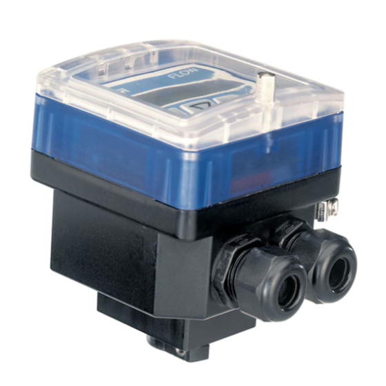
Page 2: Batch Controller Se35
This symbol appears in the delivery must include: manual to call special attention to instructions that affect the safe -1 Batch Controller electronic SE35 installation, function and use of -1 Instruction manual SE35 the product. -1 Instruction manual S030 Inline Compare the type specification on the 1.4 Electromagnetic compatibility... -
Page 3: Specification
The batch controller 8035 is consisting of a S030 fitting which houses the paddle-wheel and an electronic controller SE35, specially designed to be installed on the fitting. Use a separate order N° for the S030 Fitting. For more informations about the fittings see the corresponding instruction manual. -
Page 4: Design And Measuring Principle
[T]") (§ 4.3.3) inline fitting (S030). The controller SE35 Batch is mounted on a pipe in series with the valve. The SE35 unit measures the flow, calculates the volumes, and operates the valve(s) according to the selected program (see § 4). - Page 5 2 DESCRIPTION BATCH CONTROLLER SE35 2.4 Batch Controler 8035 INLINE external dimensions (mm) " 4.81 4.69 4.73 4.85 5.00 5.28 The height H is independant from the connection type and material of the fitting. Fig. 1 Batch Controler 8035 INLINE external dimensions...
-
Page 6: Technical Data
2 SPECIFICATION BATCH CONTROLLER SE35 2.4 Technical Data Pipe diameter from DN 15 to DN 50 (1/2" to 2") Measuring range 0,3 to 10 m/s (1.0 to 32.8 ft/s) flow range as from 3 l/min (DN15 pipe, 0.3 m/s flow velocity) flow range as from 0.8 gpm (1/2"... -
Page 7: Installation
BATCH CONTROLLER SE35 3.1 Installation Guidelines The controller SE35 Batch INLINE can only be used to measure pure, liquid and water-like fluids (solids content ≤ 1%, viscosity max. 300 cSt with on-line calibration). Observe pressure-temperature dependence according to the respective fitting materials. -
Page 8: Process Mounting
BATCH CONTROLLER SE35 3 INSTALLATION 3.2 Process mounting The flow controller electronic module SE35 Batch INLINE can be easily installed in pipes using the specially designed fitting system S030 INLINE. 1. The fitting must be installed into the pipe according to the installation specifications (see §... -
Page 9: General Electrical Connection
13: Relay 1 see § 4.4.7 Fig. 4 Pin assignment SE35 Batch Note: The driver unit supply voltage can be used for the binary inputs and the indicator lamp output (open collector). In this case the common terminal (6) and the L- terminal (8) should be connected together. - Page 10 3 INSTALLATION BATCH CONTROLLER SE35 3.5. Electrical Connections for a Supply Voltage of 230/115 VAC (option) Remove the cover from the unit, the power supply board is on the bottom of the housing. Pull the cable through a PG 13.5 cable gland and wire according to fig. 5. The other connections will be the same as on the standard version §...
-
Page 11: Controller Operating And Control Elements
4 OPERATION BATCH CONTROLLER SE35 The operation is classified according to three levels. A) Display This menu allows the user to control the dosing by the keypad (start, pause, reset, stop); using the LCD display, he can monitor the flow rate and the initial preset volume throughout the dosing operation. -
Page 12: Description Of The Dosing Options
4 CONFIGURATION BATCH CONTROLLER SE35 4.2 Description of Dosing Options Dosing options are selected within the «OPTION» sub-menu of the Calibration Menu. ( § 4.4.4.) 4.2.1. «LOC.MANU» Option» When this option is selected, the prompt «BATCH M» is displayed within the main menu. It enables the generation of a volume which can be defined using the keypad. -
Page 13: Ext.mem» Option
4 CONFIGURATION BATCH CONTROLLER SE35 4.2.4 »EXT.MEM» Option Generation of a volume previously entered into the memory (7 in total) from a remote position by using the binary data inputs (See § 4.2.2.). The following example describes the various methods of connection. -
Page 14: Ext.[T]» Option
4 CONFIGURATION BATCH CONTROLLER SE35 4.2.5. «EXT. [T]» Option Delvery of a volume proportional to the duration of the high level on the input 1 (see § 4.3.3.). The proportional relationship is as follows: X = Volume = (A x t) +B A Coefficient of proportionality (/s;...) -
Page 15: Main Menu
4 CONFIGURATION BATCH CONTROLLER SE35 4.3 Main menu Within the main menu, following readouts are available: Dosing in manual mode (see § 4.3.1.). BATCH M Only available if the «LOC.MEM» or the «MEM+MANU» Options have been selected within the Calibration menu (see § 4.4) Dosing in automatic mode (see §... - Page 16 4 CONFIGURATION BATCH CONTROLLER SE35 4.3.2. Dosing in automatic mode («LOC.MEM», «MEM+MANU», or «EXT.MEM» Options) Generation of the volume from one of the 7 values previously entered into the memory. The selected volume can be initiated either from the keypad or by the binary inputs.
-
Page 17: Display Of Flow Rate And The Initial Preset Volume During The Dosage
4 CONFIGURATION BATCH CONTROLLER SE35 4.3.3. Dosing proportional to a pulse duration («EXT.[T]» Option) This option enables the initiation of a dosing volume proportional to the time during which binary data input 1 is enabled. The following prompts are displayed within the principal menu during the dosing operation. -
Page 18: Pause / Reset Function
4 CONFIGURATION BATCH CONTROLLER SE35 4.3.5. Pause / reset function A current dosage can be momentarily or definitively stopped (except mode EXT [T]). a) Modes MEM+MANU, LOC.MEM, LOC.MANU : Current batch Countdown of the ENTER CONTINUE ENTER dosage operation in... -
Page 19: Calibration Menu
4 CONFIGURATION BATCH CONTROLLER SE35 ENTER 4.4. Calibration Menu: pressing simultaneously for 5 seconds Within this menu, the following parameters may be set: Choice of language used for prompts (German, English, French, LANGUAGE Italian, etc.) Choice of measurement unit used for volume, flow rate and UNIT counters. -
Page 20: K-Factor
4 CONFIGURATION BATCH CONTROLLER SE35 4.4.2 Unit ENTER ENTER ENTER m LITER UNIT BATCH LIT/SEC LITER LIT/MIN LIT/H 0..9 US GAL M3/MIN IMP GAL M3/H UGAL/SEC UGAL/MIN UGAL/H IGAL/SEC IGAL/MIN IGAL/H ENTER TOTAL ENTER LITER US GAL IMP GAL ENTER K-FACTOR Note: Return to the main menu is only available from the «TOTAL»... -
Page 21: Dosing Options
4 CONFIGURATION BATCH CONTROLLER SE35 Note: The device uses the last K-factor entered or determined . ENTER ENTER K-FACTOR TEACH N 000.00 Entering of K-factor as specified in the charts. 0..9 K = 046.60 ENTER OPTION 0000.0 TEACH O END DOSE... - Page 22 4 CONFIGURATION BATCH CONTROLLER SE35 OPTION LOC.MEM V1 = 00000 V7 = 00000 ENTER ENTER 0..9 0..9 V1 = 00100 V7 = 00700 ENTER OVERFILL ENTER LOC.MANU ENTER OVERFILL MEM + MANU V7 = 00000 V1 = 00000 ENTER 0..9 0..9...
-
Page 23: Overfill Correction
4 CONFIGURATION BATCH CONTROLLER SE35 4.4.5. Overfill correction The 8035 Batch controller has an overfill correction facility. It memorises the fluid volume which flows after the closure of the valve so that this volume can be deducted from the next batch. -
Page 24: Relays
4 CONFIGURATION BATCH CONTROLLER SE35 4.4.7. Relays The 8035 Batch controller provides 2 relays: - Relay 1 controls the opening of the main valve (high flow rate). A delay before activation may be selected and the operating polarity may be inverted; the user also has the facility of setting the percentage of the selected volume to be delivered through the main valve (high flow rate). - Page 25 4 CONFIGURATION BATCH CONTROLLER SE35 RELAY 1 DEL = RELAY ENTER ENTER 0..9 DEL = 020 ENTER 0..9 INV NO 85 % ENTER INV YES ENTER ALARM INV NO RELAY 2 ENTER ENTER INV YES TOTAL ENTER END DOSE INV NO...
-
Page 26: Totalizer
4 CONFIGURATION BATCH CONTROLLER SE35 4.4.8 Totalizer Simultaneous setting of both counters to zero. This facility becomes operational when the user presses the ENTER key while in the «END» option within the Calibration menu. TOTAL RES NO ENTER RES YES... -
Page 27: Check On Operation Of Relays
4 CONFIGURATION BATCH CONTROLLER SE35 «EXT. [T] Option In this option, the user can check the pulse duration being sent to the 8035 Batch controller. EXT.ACT. ENTER 0.00 SEC ..SEC 5.35 SEC Start of pulse End of pulse... -
Page 28: Maintenance
5 MAINTENANCE BATCH CONTROLLER SE35 5.1 Fault prompts 5.1.1. « ALARM » prompt "ALARM" PROMPT DURING A DOSAGE The « ALARM « prompt will be displayed during a dosage operation (irrespective of the dosage option) if one or both valves are open but the controller does not detect any flow. - Page 29 5 MAINTENANCE BATCH CONTROLLER SE35 c) Dosage through Binary Inputs and activated by EXT.MEM : Device ready for a ALARM RESET new batch (see 4.3.3) Choice "Continue" can only be made on keypad. Current batch CONTINUE continues (**) When in mode EXT.MEM or EXT [T], you can also press the Enter key on the keypad.
-
Page 30: Transducer Maintenance
BATCH CONTROLLER SE35 5.1.2.«[T] ERROR» prompt This error prompt only occurs in the «EXT.[T]» option. It is displayed during a dosing operation if the duration of the pulse is greater than 300 seconds, or if it is greater than the duration necessary to deliver the relevant volume. -
Page 31: Spare Parts List
5 MAINTENANCE BATCH CONTROLLER SE35 5.3 Factory setting of Batch controller SE35 INLINE on delivery Overfill correction: Language: English Alarm DURING: On, DEL1 = 100 Unit flow: Alarm AFTER: On, DEL2 = 100 Unit totalizers: Relay 1: DEL = 000... - Page 32 BATCH CONTROLLER SE35 E-32- 8035...
-
Page 33: Flow Chart (L/Min, Dn In Mm And M/S
SE35 ANHANG - ANNEX - ANNEXE Durchfluss-Diagramm (l/s, l/min, m /h, DN in mm und m/s) Flow chart (l/s, l/min, m /h, DN in mm und m/s) Abaque débit/vitesse/diamètre (l/s, l/min, m /h, DN en mm et m/s) 5000 l/min... - Page 34 SE35 ANHANG - ANNEX - ANNEXE Durchfluss-Diagramm (gpm, DN in inch und fps) Flow chart (gpm, DN in inch and fps) Abaque débit/vitesse/diamètre (US-gallon/min, DN en inch et ft/s) 16'' 20000 14'' 12'' 10000 10'' 5000 2000 1000 2 1/2''...
- Page 35 SERVICE Australia Burkert Fluid Control Systems Bürkert Contromatic Niederlassung Dresden Unit 1 No.2, Welder Road China/HK Ltd. Christian Bürkert Straße 2 Seven Hills NSW 2147 Guangzhou Representative Office D-01900 Großröhrsdorf Tel +61 (0) 2 967 461 66 Rm. 1305, Tower 2...
- Page 36 Tel +48 (0) 22 840 60 10 Turkey Fax +48 (0) 22 840 60 11 Bürkert Contromatik Akiskan Kontrol Sistemleri Ticaret Singapore Burkert Contromatic Singapore Pte.Ltd. 1203/8 Sok. No. 2-E No.11 Playfair Road Yenisehir Singapore 367986 Izmir Tel +65 383 26 12...
Need help?
Do you have a question about the SE35 and is the answer not in the manual?
Questions and answers