Burkert 8025 Operating Instructions Manual
Batch controller
Hide thumbs
Also See for 8025:
- Operating instructions manual (178 pages) ,
- Quick start manual (174 pages) ,
- Instruction manual (138 pages)

Related Manuals for Burkert 8025


Summary of Contents for Burkert 8025
- Page 1 Type 8025 - 8035 - SE35 BATCH Batch controller Dosiergerät Contrôleur de dosage Operating Instructions Bedienungsanleitung Manuel d‘utilisation...
- Page 2 We reserve the right to make technical changes without notice. Technische Änderungen vorbehalten. Sous réserve de modifications techniques. © Bürkert SAS, 2013 - 2016 Operating Instructions 1608/3_EU-ML 00564510 / Original FR...
-
Page 3: Table Of Contents
..........16 6.1.1 Conditions of use of a 8025 Batch in compact version ............16 6.1.2 Conformity to standards and directives of a 8025 Batch in compact version ....16 6.1.3 Fluid data of a 8025 Batch in compact version .................17 6.1.4 Material data of a 8025 Batch in compact version ..............18... - Page 4 Dimensions of a 8025 Batch in panel version ................20 6.2.5 Electrical data of a 8025 Batch in panel version ...............20 6.2.6 Specifications of a remote flow sensor connected to a 8025 Batch in panel version ..21 technical data of the dosing controller 8025 batch in wall-mounted version .........22 6.3 6.3.1 Conditions of use of a 8025 Batch in wall-mounted version ..........22...
- Page 5 ........................41 8.1 safety instructions ................................41 8.2 specifications of the connection cables .......................42 8.2.1 Dosing controller 8025 Batch in compact version, 8035 Batch and SE35 Batch ...42 8.2.2 Dosing controller 8025 Batch in panel version .................43 8.2.3 Dosing controller 8025 Batch in wall-mounting version ............43 equipotentiality of the installation ..........................43 8.3...
- Page 6 Type 8025 - 8035 - SE35 BATCH 8.14 Wiring the relay outputs Do2 and Do3 of a device ..................59 commissioning ...................................60 safety instructions ................................60 9.1 commissioning procedure ............................60 9.2 operAting AnD functions ..............................61 10.1 safety instructions ................................61 10.2 operating levels of the device .............................61 10.3 Description of the navigation keys and the state leDs .................63 10.4 using the navigation keys ..............................64 10.5 principle of a dosing and plc scenarios ......................65 10.6 Details of the process level ............................68 10.6.1 Doing a dosing in dosing mode "LOC. MANU." or "MEM.+MANU." ........69 10.6.2...
- Page 7 Type 8025 - 8035 - SE35 BATCH 10.7.15 Configuring the overfill correction or deactivating it ............... 103 10.7.16 Activating / deactivating the generation of alarms for problems occurring during a dosing ..........................105 10.7.17 Activating / deactivating the generation of alarms for problems occurring at the end of a dosing .........................
- Page 8 Type 8025 - 8035 - SE35 BATCH mAintenAnce AnD troubleshooting ........................128 11.1 safety instructions ................................. 128 11.2 cleaning the device ................................ 128 11.3 if you encounter problems ............................128 11.3.1 Resolution of problems when the device state LED is OFF..........128 11.3.2 Resolution of problems related to an error message and the device state LED is red . 129 11.3.3...
-
Page 9: About These Operating Instructions
Type 8025 - 8035 - SE35 BATCH AbouttheseOperatingInstructions ABouT THESE opErATing inSTruCTionS These Operating Instructions describes the entire life cycle of the device. Please keep these Operating Instruc- tions in a safe place, accessible to all users and any new owners. these operating instructions contains important safety information. Failure to comply with these instructions can lead to hazardous situations. Pay attention in particular to the chapters 3 Basic safety information and 2 Intended use. -
Page 10: Definition Of The Word "Device
Definition of the word "device" The word "device" used within these Operating Instructions always refers to: • the dosing controller type 8025 Batch in compact version, • the dosing controller type 8025 Batch in panel version, • the dosing controller type 8025 Batch in wall-mounted version, •... -
Page 11: Basic Safety Information
▶ Disconnect the electrical power for all the conductors and isolate it before carrying out work on the system. ▶ All equipment connected to the wall-mounted or panel version of the flow transmitter 8025 must be double insulated in relation to the mains in accordance with IEC standard 61010-1:2010. -
Page 12: General Information
The condition governing the legal warranty is the conforming use of the device in observance of the operating conditions specified in these operating instructions. 4.3 information on the internet You can find the Operating Instructions and technical data sheets regarding the type 8025 Batch, 8035 Batch and SE35 Batch at: www.burkert.com English... -
Page 13: Description
The conversion coefficient (K-factor) expressed in pulses per litre is given in the Operating Instructions for the S020 fitting used, available under www.burkert.com B : Dosing controller with display and 2 cable glands Fig. 1 : Construction of the 8025 Batch in compact version English... -
Page 14: Construction Of The 8025 Batch In Panel Version
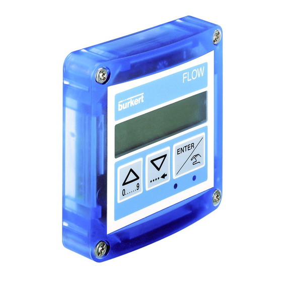
Type 8025 - 8035 - SE35 BATCH Description 5.2.2 Construction of the 8025 Batch in panel version The 8025 Batch in panel version is a dosing controller in an open housing with display. Fig. 2 : Construction of the 8025 Batch in panel version 5.2.3 Construction of the 8025 Batch in wall-mounted version The 8025 Batch in wall-mounted version is a dosing controller with display and 5 cable glands. -
Page 15: Construction Of The Se35 Batch With Sensor-Fitting S070 Or S077
Type 8025 - 8035 - SE35 BATCH Description 5.2.6 Construction of the SE35 Batch with sensor-fitting S070 or S077 A: S070 or S077 sensor-fitting including the flow sensor with oval gears. Set in rotation by the flow, the magnets integrated in the oval gears generate pulses, the frequency of which is proportional to the volume of fluid. A conversion coefficient specific to each pipe (material and diameter) is necessary to establish the flow rate value associated with the measurement. -
Page 16: Technical Data
Type 8025 - 8035 - SE35 BATCH Technicaldata TECHniCAl DATA 6.1 Technical data of the dosing controller 8025 Batch in compact version 6.1.1 Conditions of use of a 8025 Batch in compact version Ambient temperature • 12...36 V DC version • –10...+60°C • 115/230 V AC version • –10...+50°C • UL and CSA version • 0...+40°C Air humidity < 80%, non condensated protection rating IP65, according to EN 60529... -
Page 17: Fluid Data Of A 8025 Batch In Compact Version
Determined in the following reference conditions: medium = water, water and ambient temperatures 20 °C, min. upstream and downstream distances respected, appropriate pipe dimensions P (bar) Metal PVDF PVDF (PN10) PVC + PP PVC (PN10) PP (PN10) T (°C) A: Operating range Fig. 8 : Fluid temperature/pressure dependency curves for the 8025 Batch in compact version, depending on the material the S020 fitting is made of English... -
Page 18: Material Data Of A 8025 Batch In Compact Version
• FKM (optional EPDM) • Fitting S020 • Refer to the Operating Instructions of the fitting 6.1.5 Dimensions of a 8025 Batch in compact version → Please refer to the technical data sheets regarding the dosing controller type 8025 Batch in compact version, available at: www.burkert.com 6.1.6 Electrical data of a 8025 Batch in compact version 12...36 V Dc power supply... -
Page 19: Technical Data Of The Dosing Controller 8025 Batch In Panel Version
Type 8025 - 8035 - SE35 BATCH Technicaldata • protection • galvanically insulated, and protected against over- voltages, polarity reversals and short-circuits relay output Do2 and Do3 • operating • hysteresis, adjustable thresholds, normally open • DO2 function • valve 100%, cannot be modified • DO3 function • alarm (can be configured and parametered) •... -
Page 20: Material Data Of A 8025 Batch In Panel Version
Frontfoil / Screws Polyester / Stainless steel Cable glands Identification label Polyester 6.2.4 Dimensions of a 8025 Batch in panel version → Please refer to the technical data sheets regarding the dosing controller type 8025 Batch in panel version, available at: www.burkert.com 6.2.5 Electrical data of a 8025 Batch in panel version 12...36 V Dc power supply • filtered and regulated •... -
Page 21: Specifications Of A Remote Flow Sensor Connected To A 8025 Batch In Panel Version
• 36 V DC input impedance depends on the position of selector "LOAD" on the electronic board of the 8025 Batch in panel version. See chap. 8.7 and 8.9. power supply • dosing controller supplied supplied by the dosing controller depending on the position of selector with a 12...36 V DC voltage... -
Page 22: Technical Data Of The Dosing Controller 8025 Batch In Wall-Mounted Version
Type 8025 - 8035 - SE35 BATCH Technicaldata 6.3 Technical data of the dosing controller 8025 Batch in wall-mounted version 6.3.1 Conditions of use of a 8025 Batch in wall-mounted version Ambient temperature –10...+60°C Air humidity < 80%, non condensated protection rating IP65, according to EN 60529 device wired, cable glands tightened, cover lid screwed tight and entry item nuts of the cable glands tightened at a screwing torque of 1.5 Nm. -
Page 23: Dimensions Of A 8025 Batch In Wall-Mounted Version
Type 8025 - 8035 - SE35 BATCH Technicaldata 6.3.4 Dimensions of a 8025 Batch in wall-mounted version → Please refer to the technical data sheets regarding the dosing controller type 8025 Batch in wall-mounted version, available at: www.burkert.com 6.3.5 Electrical data of a 8025 Batch in wall-mounted version 12...36 V Dc power supply • filtered and regulated • SELV circuit (safety extra low voltage), with a safe energy level •... -
Page 24: Specifications Of A Remote Flow Sensor Connected To A 8025 Batch In Wall-Mounted Version
• 36 V DC input impedance depends on the position of selector "LOAD" on the electronic board of the 8025 Batch in wall-mounted version. See chap. 8.8 and 8.9. power supply • dosing controller supplied supplied by the dosing controller depending on the position of selector with a 12...36 V DC voltage... -
Page 25: Technical Data Of The Dosing Controller Se35 Batch
Type 8025 - 8035 - SE35 BATCH Technicaldata 6.4 Technical data of the dosing controller SE35 Batch The technical data of the flow transmittedosing controller SE35 Batch can be restricted by the sensor-fitting used. ▶ Please refer to the Operating Instructions of the concerned sensor-fitting. 6.4.1 Conditions of use of a SE35 Batch Ambient temperature • 12...36 V DC version •... -
Page 26: Dimensions Of A Se35 Batch
Type 8025 - 8035 - SE35 BATCH Technicaldata 6.4.4 Dimensions of a SE35 Batch → Please refer to the technical data sheet regarding the dosing controller type SE35 Batch, available at: www.burkert.com 6.4.5 Electrical data of a SE35 Batch 12...36 V Dc power supply • filtered and regulated • SELV circuit (safety extra low voltage), with a safe energy level •... -
Page 27: Technical Data Of The Dosing Controller 8035 Batch
Type 8025 - 8035 - SE35 BATCH Technicaldata Digital inputs Di1 to Di4 • commutation threshold V • 5...36 V DC • commutation threshold V max. • 2 V DC • min. pulse duration • 100 ms • input impedance • 9,4 kW • protection • galvanically isolated, and protected against polarity reversals and voltage spikes 6.5... -
Page 28: Fluid Data Of A 8035 Batch
Type 8025 - 8035 - SE35 BATCH Technicaldata ul-certification Finished products with variable key PU01 or PU02 are UL-certified products and comply also with the following standards: • UL 61010-1 • CAN/CSA-C22.2 n°61010-1 identification on the device certification Variable key UL-recognized PU01 Measuring Equipment UL-listed PU02 ® EXXXXXX 6.5.3... -
Page 29: Material Data Of A 8035 Batch
Type 8025 - 8035 - SE35 BATCH Technicaldata P (bar) métal PVDF PVDF (PN10) PVC + PP PVC (PN10) PP (PN10) T (°C) +100 A: Operating range Fig. 9 : Fluid temperature/pressure dependency curves for a dosing controller type 8035 Batch, depending on the material the S030 sensor-fitting is made of 6.5.4 material data of a 8035 Batch part material Housing, cover, lid, nut Frontfoil / Screws Polyester / Stainless steel Cable glands... -
Page 30: Technical Data Of The Dosing Controller Se35 Batch Associated With A Sensor-Fitting S070 Or S077
Type 8025 - 8035 - SE35 BATCH Technicaldata 6.6 Technical data of the dosing controller SE35 Batch associated with a sensor-fitting S070 or S077 The technical data of the dosing controller SE35 Batch may be restricted by the S070 or S077 sensor- fitting used. ▶ Please refer to the Operating Instructions of the concerned sensor-fitting S070 or S077. 6.6.1... -
Page 31: Fluid Data Of A Se35 Batch With A S070 Or A S077
Type 8025 - 8035 - SE35 BATCH Technicaldata ul-certification Finished products with variable key PU01 or PU02 are UL-certified products and comply also with the following standards: • UL 61010-1 • CAN/CSA-C22.2 n°61010-1 identification on the device certification Variable key UL-recognized PU01 Measuring Equipment UL-listed PU02 ® EXXXXXX 6.6.3... -
Page 32: Material Data Of A Se35 Batch With A S070 Or A S077
Type 8025 - 8035 - SE35 BATCH Technicaldata 6.6.4 material data of a SE35 Batch with a S070 or a S077 part material Housing, cover, lid, nut Frontfoil / Screws Polyester / Stainless steel Cable glands Identification label Polyester Wetted parts • Sensor-fitting S070 • Refer to the Operating Instructions of the concerned sensor-fitting 6.6.5 Dimensions of a SE35 Batch with a S070 or a S077 → Please refer to the technical data sheets regarding the dosing controller type SE35 Batch and the sensor- fittings type S070 and S077 , available at: www.burkert.com... -
Page 33: Fluid Installation
▶ Disconnect the electrical power for all the conductors and isolate it before carrying out work on the system. ▶ All equipment connected to the wall-mounted or panel version of the flow transmitter 8025 must be double insulated in relation to the mains in accordance with IEC standard 61010-1:2010. -
Page 34: Installation Of The Dosing Controller Type 8025 Batch In Compact Version
7.2 installation of the dosing controller type 8025 Batch in compact version The dosing controller 8025 Batch is inserted into an S020 fitting mounted on the pipes: 1. Install the S020 fitting on the pipes, 2. Install the 8025 Batch in compact version into the S020 fitting, 3. Finalise the installation of the 8025 Batch in compact version. -
Page 35: Install The 8025 Batch In Compact Version Into The S020 Fitting
Type 8025 - 8035 - SE35 BATCH Fluidinstallation Filling of the pipe Filling of the pipe and fluid flow circulation in horizontal mounting in vertical mounting Correct Incorrect Correct Incorrect shows the fluid flow direction Air bubbles within the pipe Correct Incorrect Correct Incorrect Fig. 11 : Filling of the pipe, flow direction of the fluid, Vertical mounting Air bubbles within the pipe 7.2.2 install the 8025 Batch in compact version into the S020 fitting →... -
Page 36: Installation Of The Dosing Controller 8035 Batch
Type 8025 - 8035 - SE35 BATCH Fluidinstallation 7.3 installation of the dosing controller 8035 Batch The dosing controller type 8035 Batch comprises a dosing controller type SE35 Batch and a sensor-fitting type S030. The dosing controller SE35 Batch is assembled on the sensor-fitting S030 by a quarter-turn rotation system: 1. Install the S030 sensor-fitting on the pipes, 2. -
Page 37: Finalise The Installation Of The 8035 Batch
Type 8025 - 8035 - SE35 BATCH Fluidinstallation 7.3.3 finalise the installation of the 8035 Batch → Wire the device and switch it on (see chap. 8). → Set the K-factor or determine it with Teach-In (see chap. 10.7.3 or 10.7.4). 7.4 installation of the dosing controller SE35 Batch on the sensor-fitting S070 or S077 The dosing controller SE35 Batch is installed on the pipes using the sensor-fitting S070 or S077. The dosing controller SE35 Batch is assembled on the sensor-fitting S070 or S077 by a quarter-turn system: 1. -
Page 38: Install The Dosing Controller Se35 Batch On The Sensor-Fitting S070 Or S077
Install the 8025 Batch in panel version in a cabinet with a protection class at least IP54 to ensure a degree of pollution 2 inside the cabinet. → Respect the dimensions indicated in Fig. 16 to cut the opening in the cabinet door. - Page 39 Washer Cable clip Seal Fig. 17 : I nstallation of the 8025 Batch in panel version → Insert the 4 screws in the housing (from the front). If the cabinet door is too thick use the 4 supplied M4*25 screws. → Insert the seal on the external threads of the 4 screws (rear of the housing).
-
Page 40: Installation Of The Dosing Controller 8025 Batch In Wall-Mounted Version
Type 8025 - 8035 - SE35 BATCH Fluidinstallation 7.6 installation of the dosing controller 8025 Batch in wall-mounted version note risk of material damage if the cable glands are not tightly screwed on the housing ▶ Before installing the wall-mounted housing on its support, tighten the nuts of the entry item of the cables glands at a torque of 1.5 Nm. The device in a wall-mounted version has 4 holes in the bottom of the housing. -
Page 41: Electrical Installation And Wiring
▶ Disconnect the electrical power for all the conductors and isolate it before carrying out work on the system. ▶ All equipment connected to the wall-mounted or panel version of the flow transmitter 8025 must be double insulated in relation to the mains in accordance with IEC standard 61010-1:2010. -
Page 42: Specifications Of The Connection Cables
Type 8025 - 8035 - SE35 BATCH ElectricalinstallationandWiring Warning risk of injury due to unintentional switch on of power supply or uncontrolled restarting of the installation. ▶ Take appropriate measures to avoid unintentional activation of the installation. ▶ Guarantee a set or controlled restarting of the process subsequent to any intervention on the device. • Use a filtered and regulated 12...36 V DC power supply. The circuit has to be safety extra low voltage (SELV), with a safe energy level. -
Page 43: Dosing Controller 8025 Batch In Panel Version
Type 8025 - 8035 - SE35 BATCH ElectricalinstallationandWiring 8.2.2 Dosing controller 8025 Batch in panel version The electrical connection is done directly on the terminal blocks of the electronics. specifications of cables and conductors recommended values • Cable type • Shielded (not supplied) • Cross section of wires • 0,2...1,5 mm • Length • max. 50 m •... - Page 44 Plastic pipes (*) If a direct earth connection is not possible, fit a 100 nF/50 V capacitor between the negative power supply terminal and the earth. Fig. 20 : 8025 Batch in compact version, 8035 Batch and SE35 Batch, equipotentiality skeleton diagrams Power cable shield 8025 Batch, panel- or Power supply wall-mounted Flow sensor Valve, pump,...
-
Page 45: Default Position Of The Selectors
Type 8025 - 8035 - SE35 BATCH ElectricalinstallationandWiring 8.4 Default position of the selectors Only move the selectors when the power supply is off. Tab. 1 : Default positions of selectors "SENSOR SUPPLY", "LOAD" and "SENSOR TYPE" selector Default position SENSOR SUPPLY A 2.2KOhms LOAD B NPN/PNP SENSOR TYPE C 8.5 Terminal assignment and use of the selectors terminal block 2 PE: shieldings of the power supply cable and the... - Page 46 Type 8025 - 8035 - SE35 BATCH ElectricalinstallationandWiring terminal block 2 PE: shieldings of the power supply cable and the input / output cables SOURCE SINK CURRENT terminal block 3: wiring the DO2 relay output. BINARY Univ Iout (AO1) Supply PULSE Batch 12..36Vdc terminal block 4: wiring the DO3 relay output. ISOG SENSOR terminal block 5 "floW sensor": Wiring the...
- Page 47 Type 8025 - 8035 - SE35 BATCH ElectricalinstallationandWiring T 125 mA SOURCE SINK CURRENT BINARY Univ Iout (AO1) Supply PULSE Batch 12..36Vdc ISOG SENSOR SENSOR TYPE (L+)-12V COIL NPN/PNP 2.2K SUPPLY COIL FLOW SENSOR terminal block 1 terminal block 5: wiring the DO2 relay output. PE: shieldings of the power supply cable and the input / terminal block 6: wiring the DO3 relay output.
- Page 48 Type 8025 - 8035 - SE35 BATCH ElectricalinstallationandWiring SOURCE SINK CURRENT BINARY Iout Univ (AO1) Supply PULSE Batch 12..36Vdc ISOG SENSOR SENSOR TYPE (L+)-12V COIL NPN/PNP 2.2K SUPPLY COIL FLOW 5 6 7 8 9 10 SENSOR terminal block 1 terminal block 5: wiring the DO2 relay output. PE: factory wired shield.
-
Page 49: Wiring The 8025 Batch In Compact Version, The 8035 Batch Or The Se35 Batch
Type 8025 - 8035 - SE35 BATCH ElectricalinstallationandWiring 8.6 Wiring the 8025 Batch in compact version, the 8035 Batch or the SE35 Batch Only move the selectors when the power supply is off. Insert the supplied stopper gasket into the unused cable gland to ensure the tightness of the device. • Unscrew the unused cable gland. • Remove the transparent disk. - Page 50 Type 8025 - 8035 - SE35 BATCH ElectricalinstallationandWiring Tab. 2 : Position of selectors "SENSOR TYPE", "SENSOR SUPPLY" and "LOAD" on the 8025 Batch in compact version, the 8035 Batch or the SE35 Batch Selector "SENSOR SUPPLY" Selector "LOAD" SENSOR Selector "SENSOR TYPE" 2.2K (L+)-12V The flow sensor of the device needs a minimum voltage supply of 5 V DC : → If the device is fed with a voltage ≥ 12 V DC and →...
-
Page 51: Wiring The 8025 Batch In Panel Version
→ Set the selectors "SENSOR TYPE", "SENSOR SUPPLY" and "LOAD": see chap. 8.9 Connecting the remote flow sensor to a 8025 Batch in panel-mounted or in wall-mounted version. → Before wiring the device insert the supplied cable clips into the slots of the electronic board. - Page 52 Type 8025 - 8035 - SE35 BATCH ElectricalinstallationandWiring Selector D makes it possible to configure the supply voltage of the device in a 115/230 V AC version. → Energize the device with a → Energize the device with a 230V 230 V AC voltage. 115 V AC voltage.
-
Page 53: Connecting The Remote Flow Sensor To A 8025 Batch In Panel-Mounted Or In Wall-Mounted Version
Only move the selectors when the power supply is off. Before connecting the flow sensor to the dosing controller 8025 Batch, in panel-mounted or in wall- mounted version: • Set selector "SENSOR TYPE" depending on the output signal originating from the flow sensor. See Fig. - Page 54 Type 8025 - 8035 - SE35 BATCH ElectricalinstallationandWiring Tab. 3 : Position of selectors "SENSOR TYPE" and "LOAD" of the 8025 Batch in panel or in wall-mounted version, and terminal assignment of terminal block "FLOW SENSOR" depending on the signal emitted by the remote flow sensor Terminal assignment of Selector "LOAD" terminal block "FLOW Selector Selector Type of signal SENSOR" "SENSOR "SENSOR emitted by the TYPE" SUPPLY" remote flow SUPPLY 2.2K COIL sensor FLOW SENSOR 8025 39 kΩ → Set selector "LOAD" on 3 PE →...
-
Page 55: Wiring The Digital Inputs Di1 To Di4 And The Transistor Output Do4
Type 8025 - 8035 - SE35 BATCH ElectricalinstallationandWiring Terminal assignment of Selector "LOAD" terminal block "FLOW Selector Selector Type of signal SENSOR" "SENSOR "SENSOR emitted by the TYPE" SUPPLY" remote flow SUPPLY 2.2K COIL sensor FLOW SENSOR 8025 +3 V 3 PE → Set selector "LOAD": →... -
Page 56: Wiring The Do1 Transistor Output Of Device, Fed With 12
Type 8025 - 8035 - SE35 BATCH ElectricalinstallationandWiring 8.11 Wiring the Do1 transistor output of device, fed with 12...36 V DC NPN wiring PNP wiring 12-36 V DC 12-36 V DC 300 mA 300 mA 5-36 VDC 5-36 VDC Power supply Power supply of the device of the device Univ Iout Univ Iout (AO1) Supply PULSE... -
Page 57: Wiring The Do1 Transistor Output Of The 8025 Batch In Wall-Mounted Version, Fed With 115/230 V Ac
Type 8025 - 8035 - SE35 BATCH ElectricalinstallationandWiring 8.13 Wiring the Do1 transistor output of the 8025 Batch in wall-mounted version, fed with 115/230 V AC Only move the selectors when the power supply is off. Position selector D depending on the value of the power supply. SOURCE SINK CURRENT BINARY Univ Iout (AO1) Supply PULSE Batch 12..36Vdc ISOG SENSOR SENSOR TYPE... - Page 58 Type 8025 - 8035 - SE35 BATCH ElectricalinstallationandWiring Position selector D depending on the value of the power supply. SOURCE SINK CURRENT BINARY Iout Univ (AO1) Supply PULSE Batch 12..36Vdc ISOG SENSOR SENSOR TYPE (L+)-12V COIL NPN/PNP 2.2K SUPPLY COIL FLOW 5 6 7 8 9 10...
-
Page 59: Wiring The Relay Outputs Do2 And Do3 Of A Device
Type 8025 - 8035 - SE35 BATCH ElectricalinstallationandWiring 8.14 Wiring the relay outputs Do2 and Do3 of a device To do a dosing, connect a valve to the relay output DO2. The device can control: • either a dosing with a single valve connected to the relay output DO2. • or a dosing with 2 valves connected to the relay outputs DO2 and DO3. In this case, connect the main valve (for the highest flow rates) to output DO2 and the auxiliary valve (for low flow rates) to output DO3. -
Page 60: Commissioning
Type 8025 - 8035 - SE35 BATCH Commissioning CommiSSioning 9.1 Safety instructions Warning Danger due to non-conforming commissioning. Non-conforming commissioning could lead to injuries and damage the device and its surroundings. ▶ Before commissioning, make sure that the staff in charge have read and fully understood the contents of the operating instructions. -
Page 61: Operating And Functions
Type 8025 - 8035 - SE35 BATCH Operatingandfunctions opErATing AnD funCTionS 10.1 Safety instructions Danger Danger due to electrical voltage. ▶ Disconnect the electrical power for all the conductors and isolate it before carrying out work on the system. ▶ Observe all applicable accident protection and safety regulations for electrical equipment. Warning risk of injury due to non-conforming operating. - Page 62 Type 8025 - 8035 - SE35 BATCH Operatingandfunctions ENTER Starts a dosing. See chap. 10.6. Process Configuration level level BAtCH M. BAtCH A. 0..9 > 2 s BAtCH R. > 2 s > 5 s ENTER BAtCH S. 0..9 0..9 87654 L Parameters Information History menu...
-
Page 63: Description Of The Navigation Keys And The State Leds
Type 8025 - 8035 - SE35 BATCH Operatingandfunctions 10.3 Description of the navigation keys and the state lEDs • Selecting the displayed • Scrolling up the parameters parameter • Confirming the settings • Incrementing the figure selected • Consulting the history of dosings State LED of relay output DO3 (LED ON = contact closed) -
Page 64: Using The Navigation Keys
Type 8025 - 8035 - SE35 BATCH Operatingandfunctions 10.4 using the navigation keys you want to... press... move between parameters within a level or a menu. • to go to the next parameter. • to go to the previous parameter. 0..9 access the Parameters menu. ENTER simultaneously for 5 s, in the Process level, if no dosing has been started. -
Page 65: Principle Of A Dosing And Plc Scenarios
Type 8025 - 8035 - SE35 BATCH Operatingandfunctions 10.5 principle of a dosing and plC scenarios CHOOSING THE DOSING QUANTITY • Output DO4 "STATE": OFF • Device state LED: green, not flashing • Valves are closed 0100.0 L ENTER DOSING • Output DO4 "STATE": ON • Device state LED: green, not flashing •... - Page 66 Type 8025 - 8035 - SE35 BATCH Operatingandfunctions Tab. 4 : Scenario of a dosing with no problem nor pause event state, output Do4 no dosing dosing end of the dosing Tab. 5 : Scenario of a dosing with pause event state, output Do4 no dosing dosing dosing interrupted dosing continued • if the dosing is not finished • if the dosing finished during the pause or reset the dosing Tab. 6 : ...
- Page 67 Type 8025 - 8035 - SE35 BATCH Operatingandfunctions Tab. 7 : Scenario of a dosing with pause and alarm during the pause event state, output Do4 no dosing dosing dosing interrupted ALARM 3.5 Hz confirm the alarm • if the dosing finished during the alarm 3.5 Hz • if the dosing is not finished: the dosing has been interrupted. See Tab. 5.
-
Page 68: Details Of The Process Level
Type 8025 - 8035 - SE35 BATCH Operatingandfunctions 10.6 Details of the process level This level is active by default when the device is energized. If the power supply of the device is shut down while a dosing is being done, the dosing has been inter- rupted when the power supply is restored: to continue or abort the dosing depending on the dosing mode that is active on the device, see chap. -
Page 69: Doing A Dosing In Dosing Mode "Loc. Manu." Or "Mem.+Manu
Type 8025 - 8035 - SE35 BATCH Operatingandfunctions 10.6.1 Doing a dosing in dosing mode "loC. mAnu." or "mEm.+mAnu." Dosing mode "LOC. MANU." allows for entering a dosing quantity and starting the dosing, via the navigation keys. Dosing mode "MEM.+MANU." allows for: • either entering a dosing quantity and starting the dosing, via the navigation keys, •... - Page 70 Type 8025 - 8035 - SE35 BATCH Operatingandfunctions • If the generation of alarms (alarm "DURING") for problems occurring during a dosing has been activated (see chap. 10.7.16), an alarm is generated if there is no flow rate measured in the pipe whereas the valves are open. See chap. 11.3.4 to solve the problem.
-
Page 71: Doing A Dosing In Dosing Mode "Loc. Mem." Or "Mem.+Manu
Type 8025 - 8035 - SE35 BATCH Operatingandfunctions ENTER → To interrupt the dosing, press : the valve connected to output DO2 and possibly the valve connected to output DO3 close, the device state LED flashes at a 1 Hz-frequency and the DO4 output (if configured to transmit the device state, see chap. - Page 72 Type 8025 - 8035 - SE35 BATCH Operatingandfunctions • If the generation of alarms (alarm "DURING") for problems occurring during a dosing has been activated (see chap. 10.7.16), an alarm is generated if there is no flow rate measured in the pipe whereas the valves are open. See chap. 11.3.4 to solve the problem.
-
Page 73: Doing A Dosing In Dosing Mode "Ext. Mem
Type 8025 - 8035 - SE35 BATCH Operatingandfunctions ENTER → To interrupt the dosing, press : the valve connected to output DO2 and possibly the valve connected to output DO3 close, the device state LED flashes at a 1 Hz-frequency and the DO4 output (if configured to transmit the device state, see chap. - Page 74 Type 8025 - 8035 - SE35 BATCH Operatingandfunctions Terminal A SOURCE SINK CURRENT BINARY Univ Iout (AO1) Supply PULSE 5-36 V DC Batch 12..36Vdc ISOG SENSOR 125 mA SENSOR TYPE (L+)-12V COIL NPN/PNP 2.2K SUPPLY COIL FLOW SENSOR signalling the dosing state for example if the output DO4 has been configured to transmit the state of the device.
- Page 75 Type 8025 - 8035 - SE35 BATCH Operatingandfunctions Process level (the digital inputs DI1, DI2 and DI3 are deactivated). 1156 L → To choose the dosing quantity from the memory, activate the digital inputs DI1, DI2, DI3: State of input DI3 State of input DI2 State of input DI1 Associated quantity →...
- Page 76 Type 8025 - 8035 - SE35 BATCH Operatingandfunctions ENTER → To interrupt the dosing, press : the valve connected to output DO2 and possibly the valve connected to output DO3 close, the device state LED flashes at a 1 Hz-frequency and the DO4 output (if configured to transmit the device state, see chap.
-
Page 77: Doing A Dosing In Dosing Mode "Ext.+Loc
Type 8025 - 8035 - SE35 BATCH Operatingandfunctions 10.6.4 Doing a dosing in dosing mode "EXT.+loC." Dosing mode "EXT.+LOC." allows for: • selecting a dosing quantity from the memory of the device, via the navigation keys or the digital inputs, • then starting the dosing via the digital input DI4 (only). Danger Danger due to electrical voltage. - Page 78 Type 8025 - 8035 - SE35 BATCH Operatingandfunctions • To select the dosing quantity via the navigation keys, deactivate the 3 digital inputs DI1 to DI3. • If a warning message is generated by the device and no dosing is being done, a long pulse (> 2 seconds) on DI4 allows for remotely accessing to the Information menu, whatever the state of the inputs DI1 to DI3.
- Page 79 Type 8025 - 8035 - SE35 BATCH Operatingandfunctions If a warning message is generated by the device and no dosing is being done, a long pulse (> 2 seconds) on DI4 allows for remotely accessing to the Information menu, whatever the state of the inputs DI1 to DI3. See chap. 10.11.
- Page 80 Type 8025 - 8035 - SE35 BATCH Operatingandfunctions ENTER → To interrupt the dosing, press : the valve connected to output DO2 and possibly the valve connected to output DO3 close, the device state LED flashes at a 1 Hz-frequency and the DO4 output (if configured to transmit the device state, see chap.
-
Page 81: Doing A Dosing In Dosing Mode "Ext. [T]
Type 8025 - 8035 - SE35 BATCH Operatingandfunctions 10.6.5 Doing a dosing in dosing mode "EXT. [T]" In this mode, the dosing starts as soon as the digital input DI1 is switched. The dosing mode "EXT. [T]" allows for starting the dosing of a quantity proportional to the duration the digital input DI1 is activated. - Page 82 Type 8025 - 8035 - SE35 BATCH Operatingandfunctions If the message "ERROR [T]" is displayed during a dosing, see chap. 11.3.4 and 10.7.11. Process level (the digital inputs DI1, DI2 and DI3 are deactivated). 1156 L → To start the dosing, activate the digital input DI1 for a duration T related to the dosing quantity.
- Page 83 Type 8025 - 8035 - SE35 BATCH Operatingandfunctions The activation duration of the digital input DI1 is counted even if the dosing has been interrupted. ENTER → To interrupt the dosing, press : the valve connected to output DO2 and possibly the valve connected to output DO3 close, the device state LED flashes at a 1 Hz-frequency and the DO4 output (if configured to transmit the device state, see chap.
-
Page 84: Doing A Dosing In Dosing Mode "Ext. Rep
Type 8025 - 8035 - SE35 BATCH Operatingandfunctions 10.6.6 Doing a dosing in dosing mode "EXT. rEp." The dosing mode "EXT. REP." allows for starting, via the digital inputs, the dosing of the quantity determined by a Teach-In procedure. Danger Danger due to electrical voltage. ▶ Disconnect the electrical power for all the conductors and isolate it before carrying out work on the system. - Page 85 Type 8025 - 8035 - SE35 BATCH Operatingandfunctions → Restart the device: • If the DI4 input is at the low level (not powered) when energizing the device, the four digital inputs will be active at high level. • If the DI4 input is at the high level (not powered) when energizing the device, the four digital inputs will be active at low level.
- Page 86 Type 8025 - 8035 - SE35 BATCH Operatingandfunctions ENTER → To interrupt the dosing, press : the valve connected to output DO2 and possibly the valve connected to output DO3 close, the device state LED flashes at a 1 Hz-frequency and the DO4 output (if configured to transmit the device state, see chap.
-
Page 87: Doing A Dosing In Dosing Mode "Loc. Rep
Type 8025 - 8035 - SE35 BATCH Operatingandfunctions 10.6.7 Doing a dosing in dosing mode "loC. rEp." The dosing mode "LOC. REP." allows for starting, via the navigation keys, the dosing of the quantity determined by a Teach-In procedure. Danger Danger due to electrical voltage. ▶ Disconnect the electrical power for all the conductors and isolate it before carrying out work on the system. - Page 88 Type 8025 - 8035 - SE35 BATCH Operatingandfunctions Process level BAtCH R. OK Y/N → Choose "OK Y" to start a new dosing. → Confirm. → Confirm. The device shows the percentage of the quantity that has been 8.5 % already dosed (symbol % blinks). → To read the flow rate measured in the pipe, press 0..9...
-
Page 89: Details Of The Parameters Menu
Type 8025 - 8035 - SE35 BATCH Operatingandfunctions 10.7 Details of the parameters menu ENTER To access the Parameters menu, simultaneously press keys for at least 5 This menu comprises the following configurable parameters: Choosing the display language LANGUAGE Choosing the dosing units, the flow rate units, the units and number of decimals of the... -
Page 90: Choosing The Display Language
Type 8025 - 8035 - SE35 BATCH Operatingandfunctions 10.7.1 Choosing the display language When the device is energized for the first time, the display language is English. LANGUAGE ENGLiSH DEUtSCH → Confirm the displayed language: the 0..9 FRANçAiS selected language is immediately active. itALiANO ESPANOL UNit Fig. 58 : Diagram of the "LANGUAGE" parameter of the Parameters menu → If you do not want to adjust another parameter, go to the "END" parameter of the Parameters menu and press ENTER to save the settings or not and go back to the Process level. - Page 91 Type 8025 - 8035 - SE35 BATCH Operatingandfunctions MLitRE UNit BAtCH LitRE → Choose the units of the dosing quantities. → Confirm. 0..9 US GAL iMP GAL KiLOGRAM POUNDS FLOW MLit/SEC US GAL/S iMP GA/S KG/SEC LB/SEC MLit/MiN US GAL/M iMP GA/M KG/MiN LB/MiN MLit/H US GAL/H...
-
Page 92: Entering The K-Factor Of The Fitting Used
Type 8025 - 8035 - SE35 BATCH Operatingandfunctions 10.7.3 Entering the K-factor of the fitting used The device determines the quantity of fluid that flows through the pipe using the fitting K-factor. The K-factor of the fitting used can be entered here. The device may also determine the K-factor using a Teach-In procedure: see chap. - Page 93 Type 8025 - 8035 - SE35 BATCH Operatingandfunctions Determining the fitting k-factor using a teach-in procedure depending on a volume ("teAch V.") • Before starting the Teach-In procedure, connect a valve to the relay output DO2. • The device uses the new K-factor as soon as "SAVE YES" is confirmed when leaving the Parameters menu. The display shows the K-factor of the fitting, last entered or determined K-FACtOR K=2.85...
- Page 94 Type 8025 - 8035 - SE35 BATCH Operatingandfunctions Determining the fitting k-factor using a teach-in procedure depending on a flow rate ("teAch f.") The device uses the new K-factor as soon as "SAVE YES" is confirmed when leaving the Parameters menu. The display shows the K-factor of the fitting, last entered or determined K-FACtOR K=10.00 using a Teach-In procedure tEACH V.
-
Page 95: Configuring The Dosing Mode (General Diagram)
Type 8025 - 8035 - SE35 BATCH Operatingandfunctions 10.7.5 Configuring the dosing mode (general diagram) Configuring the dosing mode for entering a dosing quantity and starting the dosing, via the navigation keys, See OPtiONAL MODE LOC. MANU. chap. 10.7.6. Configuring the dosing mode for starting the dosing, via the navigation keys, of a quantity saved in the memory. See LOC. -
Page 96: Configuring The Dosing Mode "Loc. Manu
Type 8025 - 8035 - SE35 BATCH Operatingandfunctions 10.7.6 Configuring the dosing mode "loC. mAnu." This dosing mode allows for entering a dosing quantity and starting the dosing, via the navigation keys. OPtiONAL MODE LOC. MANU. → Confirm. REtURN Fig. 64 : Configuring the dosing mode "LOC. MANU." → If you do not want to adjust another parameter, go to the "END" parameter of the Parameters menu and press ENTER to save the settings or not and go back to the Process level. -
Page 97: Configuring The Dosing Mode "Ext. Mem
Type 8025 - 8035 - SE35 BATCH Operatingandfunctions 10.7.9 Configuring the dosing mode "EXT. mEm." This dosing mode allows for starting the dosing, via the digital inputs, of a quantity saved in the memory. OPtiONAL MODE EXt. MEM. → Confirm. VOLUMES → Confirm. → Enter up to 7 dosing quantities into the memory. See chap. 10.7.14. - Page 98 Type 8025 - 8035 - SE35 BATCH Operatingandfunctions This dosing mode allows for starting the dosing of a quantity proportional to the activation duration of the digital input DI1, according to the formula: X = A*T + B • where A is the proportionality factor in dosing units per second, •...
-
Page 99: Configuring The Dosing Mode "Ext. Rep
Type 8025 - 8035 - SE35 BATCH Operatingandfunctions 10.7.12 Configuring the dosing mode "EXT. rEp" The dosing mode allows for starting, via the digital inputs, the dosing of the quantity determined by a Teach-In procedure. Teach-In of the dosing quantity can be done either via the digital inputs or using the navigation keys. - Page 100 Type 8025 - 8035 - SE35 BATCH Operatingandfunctions tEACH Y → To exit parameter "MODE". ABORt 0..9 → Place the tank to be filled at the end of the pipe. READY Y → Confirm by pressing the key "ENTER" or by sending out a pulse on DI4:...
-
Page 101: Configuring The Dosing Mode "Loc. Rep
Type 8025 - 8035 - SE35 BATCH Operatingandfunctions 10.7.13 Configuring the dosing mode "loC. rEp." The dosing mode allows for starting, via the navigation keys, the dosing of the quantity determined by a Teach-In procedure. Teach-In of the dosing quantity can be done either via the digital inputs or using the navigation keys. - Page 102 Type 8025 - 8035 - SE35 BATCH Operatingandfunctions tEACH Y → To exit parameter "MODE". ABORt 0..9 → Place the tank to be filled at the end of the pipe. READY Y → Confirm by pressing the key "ENTER" or by sending out a pulse on DI4:...
-
Page 103: Entering The Dosing Quantities In The Device Memory
Type 8025 - 8035 - SE35 BATCH Operatingandfunctions 10.7.14 Entering the dosing quantities in the device memory The parameter "VOLUMES" of the sub-menu "OPTIONAL" allows for entering up to 7 dosing quantities in the device memory. These quantities are then available when the dosing modes"LOC. MEM", "MEM+MANU", "EXT. MEM" or "EXT. +LOC" is active. - Page 104 Type 8025 - 8035 - SE35 BATCH Operatingandfunctions → To deactivate the overfill correction. OVERFiLL DiSABLE → Deducting the overfilling from the next dosing. DiRECt → Slightly smoothing the overfilling values of the last dosings and deducting 0..9 the calculated value from the next dosing. → Moderatly smoothing the overfilling values of the last dosings and MEDiUM deducting the calculated value from the next dosing.
-
Page 105: Activating / Deactivating The Generation Of Alarms For Problems Occurring During A Dosing
Type 8025 - 8035 - SE35 BATCH Operatingandfunctions 10.7.16 Activating / deactivating the generation of alarms for problems occurring during a dosing The following problems can occur during a dosing: • no flow in the pipe whereas the valves are open. • a flow is measured in the pipe whereas the valves are closed. These problems can be signalled by the generation of an alarm. -
Page 106: Activating / Deactivating The Generation Of Alarms For Problems Occurring At The End Of A Dosing
Type 8025 - 8035 - SE35 BATCH Operatingandfunctions 10.7.17 Activating / deactivating the generation of alarms for problems occurring at the end of a dosing When the following 3 criteria are fulfilled the dosing is finished: • no flow rate measured in the pipe, • the valves are closed, • and the quantity has entirely been dosed. If a flow rate is measured in the pipe whereas the valves should be closed (once the dosing is finished or when a dosing has been interrupted), an alarm can be generated. -
Page 107: Configuring The Outputs (General Diagram)
Type 8025 - 8035 - SE35 BATCH Operatingandfunctions 10.7.18 Configuring the outputs (general diagram) Configuring the transistor output DO1 to switch when an alarm is generated during or at the end of a dosing. See ALARM OUtPUt chap. 10.7.19. Configuring the transistor output DO1 to switch when a WARNiNG warning message is emitted by the device. See chap. 10.7.20. -
Page 108: Configuring The Transistor Output Do1 Or Do4 Or The Relay Output Do3 To Switch When An Alarm Is Generated During Or At The End Of A Dosing
Type 8025 - 8035 - SE35 BATCH Operatingandfunctions Configuring the transistor output DO4 to transmit the device OUtPUt StAtE state. See chap. 10.7.26. Configuring the transistor output DO4 to switch when an alarm is generated during or at the end of a dosing. See ALARM chap. 10.7.19. -
Page 109: Configuring The Transistor Output Do1 Or Do4 Or The Relay Output Do3 To Switch When A Warning Message Is Emitted By The Device
Type 8025 - 8035 - SE35 BATCH Operatingandfunctions 10.7.20 Configuring the transistor output Do1 or Do4 or the relay output Do3 to switch when a warning message is emitted by the device When the device generates a warning message, the device state LED is orange. The generation of a warning message can be indicated by the switching of the output DO1 and/or DO3 and/or DO4. The relay output DO3 can be configured to switch when a warning message is generated by the device, if the output is not configured to control an auxiliary valve. -
Page 110: Configuring The Transistor Output Do1 Or Do4 As A Pulse Output Proportional To A Volume Or A Mass
Type 8025 - 8035 - SE35 BATCH Operatingandfunctions OUtPUt END DOSE iNV YES 0..9 iNV NO → Choose the operating, inverted or not inverted, of the output. → Confirm. REtURN Fig. 82 : Configuring the output DO1 or DO3 or DO4 to signal the end of the dosing → If you do not want to adjust another parameter, go to the "END" parameter of the Parameters menu and press ENTER to save the settings or not and go back to the Process level. -
Page 111: Configuring The Transistor Output Do1 Or Do4 To Transmit The Rotational Frequency Of The Paddle Wheel
Type 8025 - 8035 - SE35 BATCH Operatingandfunctions OUtPUt PULSE LitRE → Choose the volume or mass unit of a pulse.The available volume units depend on the chosen dosing unit. See chap. 10.7.2. → Confirm. PU=01.000 → Enter the volume of fluid (value between 0,001 and... -
Page 112: Configuring The Relay Output Do2
Type 8025 - 8035 - SE35 BATCH Operatingandfunctions 10.7.24 Configuring the relay output Do2 Connect the main valve (installed into the pipe with high flow rate) to the relay output DO2. See chap. 8.14. The output DO2 is dedicated to the control of the main valve (installed into the pipe with high flow rate). -
Page 113: Configuring The Relay Output Do3 To Control An Auxiliary Valve
Type 8025 - 8035 - SE35 BATCH Operatingandfunctions 10.7.25 Configuring the relay output Do3 to control an auxiliary valve • Connect the auxiliary valve (installed into the pipe with low flow rate) to the relay output DO3. See chap. 8.14. • The time delay before opening the auxiliary valve is the same as the time delay before opening the main valve. -
Page 114: General Diagram Of The "Reset" Sub-Menu
Type 8025 - 8035 - SE35 BATCH Operatingandfunctions state of the device state of the the transistor output Do4 Problem which occurs during or at the end of a dosing: 3,5 Hz-frequency • no flow in the pipe whereas the valves are open. • a flow is measured in the pipe whereas the valves are closed. -
Page 115: Resetting The Two Volume Or Mass Totalizers
Type 8025 - 8035 - SE35 BATCH Operatingandfunctions 10.7.28 resetting the two volume or mass totalizers The function allows for resetting the two volume or mass totalizers. Both totalizers are reset upon confirmation of "SAVE YES" when leaving the Parameters menu. RESEt tOtAL RESEt N 0..9 RESEt Y → Choose to reset or not the two totalizers. -
Page 116: Clearing The History Table Of The Done Dosings
Type 8025 - 8035 - SE35 BATCH Operatingandfunctions 10.7.30 Clearing the history table of the done dosings The history menu is cleared upon confirmation of "SAVE YES" when leaving the Parameters menu. RESEt HiStORiC RESEt N 0..9 RESEt Y → Choose to clear or not the the history table. → Confirm BACKLit REtURN Fig. 91 : Diagram of the "HISTORIC" parameter of the sub-menu "RESET"... -
Page 117: Details Of The Test Menu
Type 8025 - 8035 - SE35 BATCH Operatingandfunctions 10.8 Details of the Test menu ENTER To access the Test menu, simultaneously press keys for at least 5 s. 0..9 This menu comprises the following configurable parameters: Checking the inputs functions. See chap. 10.8.1. tESt Di Checking the outputs functions See chap. 10.8.2. -
Page 118: Checking The Inputs Functions
Type 8025 - 8035 - SE35 BATCH Operatingandfunctions 10.8.1 Checking the inputs functions The function allows for checking the correct working of the digital inputs. The device state LED flashes during the running check of the input working. → Activate the inputs to be tested. tESt Di BASiC Di .. -
Page 119: Checking The Paddle-Wheel Operation
Type 8025 - 8035 - SE35 BATCH Operatingandfunctions → Check that the output functions correctly (closes if the tESt DO DO1 ON operating mode is not inverted or opens if the operating mode is inverted). 0..9 → Check that the output functions correctly (closes if the... -
Page 120: Monitoring The Flow Rate In The Pipe
Type 8025 - 8035 - SE35 BATCH Operatingandfunctions 10.8.4 monitoring the flow rate in the pipe A malfunction in your process or in the flow sensor may be indicated either by too low or too high a flow rate. The parameter "FLOW-W." makes it possible to monitor the flow rate. • To disable the flow rate monitoring, set W- = W+ = 0. -
Page 121: Monitoring The Value Of The Daily Volume Or Mass Totalizer
Type 8025 - 8035 - SE35 BATCH Operatingandfunctions • The transistor output DO1 or DO4 or the relay output DO3 can be configured to switch when a warning message is emitted by the device. See chap. 10.7.18. • See also "If you encounter problems" in chap. 11.3 →... -
Page 122: Saving The User Set Configuration
Type 8025 - 8035 - SE35 BATCH Operatingandfunctions • The transistor output DO1 or DO4 or the relay output DO3 can be configured to switch when a warning message is emitted by the device. See chap. 10.7.18. • See also "If you encounter problems" in chap. 11.3 →... - Page 123 Type 8025 - 8035 - SE35 BATCH Operatingandfunctions CONFiG. FACt. SEt VALiD Y/N → To exit the function, confirm "VALID N". → To restore the default configuration of the device, confirm "VALID Y". REtURN Fig. 102 : Restoring the default configuration of the device Tab. 10 : Default configuration of the device function Default value LANGUAGE English Dosing UNITS litre UNIT of the flow rate...
-
Page 124: Details Of The History Menu
Type 8025 - 8035 - SE35 BATCH Operatingandfunctions 10.9 Details of the History menu To access the History menu, press the key for at least 2 s, in the Process level. 0..9 The menu makes it possible to consult the quantities dosed in the last 10 dosings done on the device. -
Page 125: Remote Consultation And Confirmation Of The Warning Messages
Type 8025 - 8035 - SE35 BATCH Operatingandfunctions 10.11 remote consultation and confirmation of the warning messages If the power supply of the device is cut during the remote consultation, the device will generate for 2 s a few 10 Hz-pulses on the output DO4 configured with the function "STATE" and the Process level will be active when the power supply is restored. - Page 126 Type 8025 - 8035 - SE35 BATCH Operatingandfunctions 1. To remotely access to the warning messages, the PLC sends out the code 000 on the digital inputs DI1 to DI3 then 1 pulse on DI4. 2. The device generates a 200 ms pulse on the output DO4 to confirm the access to the messages; The dosing feature cannot be accessed any more.
- Page 127 Type 8025 - 8035 - SE35 BATCH Operatingandfunctions Fig. 106 : Timing chart for the remote consultation of the warning messages English...
-
Page 128: Maintenance And Troubleshooting
Type 8025 - 8035 - SE35 BATCH Maintenanceandtroubleshooting mAinTEnAnCE AnD TrouBlESHooTing 11.1 Safety instructions Danger Danger due to electrical voltage. ▶ Disconnect the electrical power for all the conductors and isolate it before carrying out work on the system. ▶ Observe all applicable accident protection and safety regulations for electrical equipment. Warning risk of injury due to non-conforming maintenance. -
Page 129: Resolution Of Problems Related To An Error Message And The Device State Led Is Red
Type 8025 - 8035 - SE35 BATCH Maintenanceandtroubleshooting 11.3.2 resolution of problems related to an error message and the device state lED is red Device output output message possible cause recommended action state Do1 and/or displayed Do2 and/ or Do3 → Check that the supply voltage 0 Hz "PWRFAIL" The supply voltage is too switched low. is between 12 and 36 V DC. The device does not →... -
Page 130: Resolution Of Problems Related To A Warning Message And The Device State Led Is Orange
Type 8025 - 8035 - SE35 BATCH Maintenanceandtroubleshooting 11.3.3 resolution of problems related to a warning message and the device state lED is orange Device output Do1 message possible cause recommended action state leD and/or Do2 displayed and/or Do3 → Check the flow rate in the pipe orange Switched "WARN. LOW" During dosing, the measured flow rate has stayed under the and its consequences on the minimum threshold for the set process. -
Page 131: Resolution Of A Problem Occurring During A Dosing
Type 8025 - 8035 - SE35 BATCH Maintenanceandtroubleshooting Device output Do1 message possible cause recommended action state leD and/or Do2 displayed and/or Do3 → Do the planned maintenance orange Switched "W. BATCH" The number of done dosings has reached the value set in operation. parameter "BATCH-W." of the → Reset the daily totalizer of the Test menu. - Page 132 Type 8025 - 8035 - SE35 BATCH Maintenanceandtroubleshooting Device output Do1 output Do4 message possible cause recommended action state leD and/or Do2 in "stAte" displayed and/or Do3 mode → Increase the values of the orange, Switched 3,5 Hz-fre- "ERROR [T]" The message 3,5 Hz quency can only appear parameters A and B in order...
-
Page 133: Resolution Of Problems Without Message Generation And The Device Status Led Is Green
Type 8025 - 8035 - SE35 BATCH Maintenanceandtroubleshooting 11.3.5 resolution of problems without message generation and the device status lED is green Device state possible cause recommended action → Check that the K-factor corresponds to the green During a dosing, the displayed quantity is increased or decreased very slowly. fitting used. → Do a Teach-In procedure to determine the K-factor of the fitting used. - Page 134 Type 8025 - 8035 - SE35 BATCH Maintenanceandtroubleshooting Device state output Do4 in message possible cause recommended action "stAte" mode displayed → Enter a higher quantity any colour "PU H LIM" The message is displayed after the pulse value has been entered per pulse. See (parameter "PU" of the transistor chap. 10.7.22.
-
Page 135: Spare Parts And Accessories
Type 8025 - 8035 - SE35 BATCH Sparepartsandaccessories SpArE pArTS AnD ACCESSoriES attention risk of injury and/or damage caused by the use of unsuitable parts. Incorrect accessories and unsuitable replacement parts may cause injuries and damage the device and the sur- rounding area. ▶ Use only original accessories and original replacement parts from Bürkert. The damaged electronic board or housing can be replaced. - Page 136 Type 8025 - 8035 - SE35 BATCH Sparepartsandaccessories spare part for the 8025 batch in compact version order code Electronic board mounted in the cover with lid, with 425 432 window, foil and four screws (position 1) Power supply board 115/230 VAC (position 2) + 553 168 mounting instruction sheet Set including: • two M20x1,5 cable glands (position 3) •...
- Page 137 Type 8025 - 8035 - SE35 BATCH Sparepartsandaccessories spare part for the 8035 batch and the se35 batch order code Electronic board mounted in the cover with lid, with 425 432 window, foil and four screws (position 1) Power supply board 115/230 VAC (position 2) + 553 168 mounting instruction sheet Set including: • two M20x1,5 cable glands (position 3) •...
-
Page 138: Packaging, Transport
Type 8025 - 8035 - SE35 BATCH Packaging,Transport pACKAging, TrAnSporT note Damage due to transport Transport may damage an insufficiently protected device. ▶ Transport the device in shock-resistant packaging and away from humidity and dirt. ▶ Do not expose the device to temperatures that may exceed the admissible storage temperature range. - Page 140 www.burkert.com...
Need help?
Do you have a question about the 8025 and is the answer not in the manual?
Questions and answers