Burkert 8311 Instruction Manual
Pressure controller
Hide thumbs
Also See for 8311:
- Instruction manual (128 pages) ,
- Operating instructions manual (96 pages) ,
- Instruction manual (106 pages)
Table of Contents
Advertisement
Quick Links
Download this manual
See also:
Instruction Manual
Advertisement
Table of Contents

Related Manuals for Burkert 8311


Summary of Contents for Burkert 8311
- Page 1 Burkert_PressureController_8311_install_D00 PRESSURECONTROLLER TYPE 8311 Instruction Manual © Bürkert 2000 Subject to technical change without notice Ref. 438972...
-
Page 2: Table Of Contents
Pressure Controller type 8311 Table of Contents 1 SAFETY INSTRUCTIONS ..................4 1.1 Utilisation ......................5 1.2 Precautions at installation and commissioning .......... 6 1.3 Conformity to standards ................6 2 DESCRIPTION ......................8 2.1 Design ......................8 2.2 Measuring principle ..................8 2.3 Available versions .................. - Page 3 6.2 Error messages .................... 26 7 ANNEX ........................28 7.1 Examples of Easy Link© with the 8311 ............28 7.2 Description of the label of the controller type 8311 ........31 7.3 Description of the label of the pressure cell ..........31 8311...
-
Page 4: Safety Instructions
SAFETY INSTRUCTIONS Pressure Controller type 8311 - Always respect the safety instructions marked by the symbol opposite as well as those included in the manual. - Ensure the max. pressure the application can reach is within the chosen pressure range. It is recommended to equip the installation with a pressure relief valve. -
Page 5: Utilisation
1.1 Utilisation - The 8311 controller has only been designed to measure the relative pressure of a liquid or a gas. - The measuring element must be solidly screwed onto its support. There will be no manufacturer warranty for damages caused by unexpected handling or wrong usage of the device. -
Page 6: Precautions At Installation And Commissioning
Pressure Controller type 8311 1.2 Precautions at installation and commissioning - When the device is powered and the cover is open, protection against electric shocks is not effective. - Always ensure the materials in contact with the medium to measure are chemically compatible. - Page 7 8311...
-
Page 8: Description
4-20 mA loop via an external controller. The controller housing can be turned by 180°. The controller type 8311 can be inserted in a Bürkert fitting type S005 or S001, before being mounted on any type of pipe. -
Page 9: Available Versions
Relay and ASI M12 and DIN 43650 connectors on request Order number table of the controllers type 8311 for the 0-2 bar, 0-5 bar, 0-20 bar and 0-50 bar pressure ranges : on request 2.4 Accessories Order number table of the accessories... -
Page 10: Technical Data
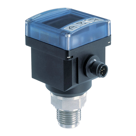
TECHNICAL DATA Pressure Controller type 8311 General features Pipe diameter any type of pipe with a DN greater than 15 and a 1/2 ‘’ threaded connection piece (G, NPT or Rc) Medium temperature -20 °C to +100 °C (- 4 °F to +212 °F) , +100 °C ( +212 °F ) with a max. ambient temperature of +40 °C (+104 °F) - Page 11 IP 65, connectors being plugged-in and tightened Environment -20 to +60° C (-4° F to +140° F), max. +40 °C (max +104 °F) if the fluid temperature is Ambient temperature near +100 °C (+212 °F) Relative humidity < 80% 8311...
- Page 12 TECHNICAL DATA Pressure Controller type 8311 Dimensions (mm) SW 27 G1/2 - NPT1/2 - Rc1/2...
- Page 13 8311...
-
Page 14: Installation
For more information, please contact your Bürkert sales office. 4.2 Mounting on the pipe We recommend to insert the controller type 8311 into a Bürkert fitting type S001 (brass or stainless steel) or type S005 before mounting it on the pipe. -
Page 15: Electrical Connection
- Tighten the cable gland. - Wire according to pin assignment (see 4.3.2) - Place gasket [4] between the 2508 connector and the fixed connector of the 8311. - Connect the 2508 connector to the 8311. - Tighten screw [1]. 8311... -
Page 16: Version With Transistor Output (Npn / Pnp)
INSTALLATION Pressure Controller type 8311 4.3.2 Version with transistor output (NPN / PNP) Sensor Receiver Sensor Receiver Load Output Output Load NPN output PNP output Ground M12 cable available as an option (reference 438 680); correspondence between the connector pin numbers and the... -
Page 17: Version With Relay Output
Always check all the connectors to ensure the good operating of the device. The device should only be started if the whole installation is in good working order. 8311... -
Page 18: Programming
5.1 General recommendations Keep in mind that the process may be influenced by all the parameter settings you make. Fill-in the table on page 24 with your settings of the controller type 8311. 5.2 Functionalities The device has three operating modes :... -
Page 19: Programming Keys
To go back to the previous function. To validate the entered data. To select the character; To go to the next function. 5.4 Default Configuration At the first powering up, the configuration of the controller type 8311 is as follows: Pressure unit: Output: hysteresis OLO:... -
Page 20: Normal Mode
PROGRAMMING Pressure Controller type 8311 5.5 Normal Mode Press the keys simultaneously Displayof the measured (see p. 22-23: ENTER pressure. Calibration Mode) N.B.: When the units flash, 0.000 the max. value of the > 5 s pressure range has been (see p. -
Page 21: Possible Switching Modes Of The 8311
5.6 Possible switching modes of the 8311 Hysteresis Mode Pressure The change of state occurs when a threshold is detected (increasing pressure: high threshold (OHI) to be detected, decreasing pressure: low threshold (OLO) to be detected). Time Not inverted Inverted... -
Page 22: Calibration Mode
PROGRAMMING Pressure Controller type 8311 5.7 Calibration Mode If you change the pressure unit, change ENTER To change the pressure unit ENTER the switching threshold values, too..(bar, psi, mPa, Torr, mmHg, 0..9 atm, MWS, mbar). ENTER... - Page 23 To calibrate the extension ENTER ENTER board (EXT) detected by the software. Extension ENTER 0..9 board data. To return (END) to the display of the pressure in the Normal mode. ENTER * To move the decimal point, press simultaneously keys 0..9 8311...
- Page 24 PROGRAMMING Pressure Controller type 8311 Configuration of the 8311 : Fill-in the table with the values programmed in the Calibration mode. Unit K fact. Mode Thresh. Inverted Delay Filter Bargraph Date Sign. UNIT Fact. K Hyst. Wind. O LO O HI Yes...
-
Page 25: Simulation Mode
To test the switching thresholds after entering a pressure value (SIM) and PRESSING THE ENTER KEY. 0..9 To return (END) to the display of the pressure in the Normal mode. ENTER * To move the decimal point, press simultaneously keys 0..9 8311... -
Page 26: Maintenance
MAINTENANCE Pressure Controller type 8311 6.1 Cleaning The controller type 8311 can be cleaned with water or any solution compatible with the materials the device is made of. For more information, please contact your Bürkert sales office. 6.2 Error messages... - Page 27 If the message appears frequently, send the device back to your Bürkert sales office. ERR 4 The 8311 controller no more measures the Perform a new Teach-In procedure (automatic pressure correctly: the process is stopped. calculation of the K-factor).
-
Page 28: Annex
ANNEX Pressure Controller type 8311 © 7.1 Examples of Easy Link with the 8311 8311 NPN connection: controller type 8311 (NPN/PNP version) and a Programmable Logic Controller. 24 V= 8311 PNP connection: Control type 8631 controller type 8311 (NPN/PNP version) and a Top Control type 8631. - Page 29 8311 NPN connection: controller type 8311 (NPN/PNP version) Solenoid valve and a solenoid < 24V, 700mA valve type 6014. Protection circuit * * Protection must be installed by the 24 V= user depending on the load, for instance, a connector type 2508 8311 with integrated varistor.
- Page 30 ANNEX Pressure Controller type 8311 8311 NO (Normally Open) connection: Solenoid valve (or controller type 8311 alarm) (relay version) and a Protection solenoid valve. circuit * 250 VAC, 24 V= 3 A max. 8311 Solenoid valve (or NC (Normally alarm)
-
Page 31: Description Of The Label Of The Controller Type 8311
7.2 Description of the label of the controller type 8311 1. Type of sensor 2. Power supply PRESSURE 8311 CERAMIC 12-30VDC 3. Output characteristics PNP 0.7A 5-30V 0.10 bar 4. Pressure range S-N:0000 5. Serial number 439934 w45LL 6. Manufacturer code 7. - Page 32 Pressure Controller type 8311 NOTES...
- Page 33 8311...
- Page 34 Pressure Controller type 8311 NOTES...
Need help?
Do you have a question about the 8311 and is the answer not in the manual?
Questions and answers