Follett E7CI100A Installation, Operation And Service Manual
Countertop ice dispenser with chewblet ice machine
Hide thumbs
Also See for E7CI100A:
- Installation, operation and service manual (40 pages) ,
- Installation, operation and service manual (48 pages)
Table of Contents
Advertisement
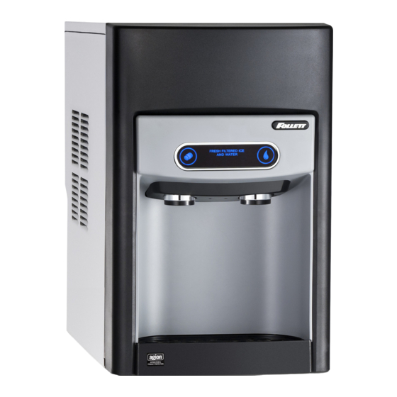
Countertop Ice Dispenser with
Chewblet
Ice Machine
®
E7CI100A, E15CI100A,
230 V/50 Hz, Rear Drain
Installation, Operation and Service Manual
E7CI100A
E15CI100A
Following installation, please forward this manual
to the appropriate operations person.
801 Church Lane • Easton, PA 18040, USA
Order parts online:
Toll free (877) 612-5086 • +1 (610) 252-7301
www.follettice.com
www.follettice.com
01103522R00
Advertisement
Table of Contents


Need help?
Do you have a question about the E7CI100A and is the answer not in the manual?
Questions and answers