Table of Contents
Advertisement
Your safety, and the safety of others, is very important. To help you make informed decisions about safety, we have
provided installation and operating instructions and other information on labels and in this guide. This information
alerts you to potential hazards that could hurt you or others. It is not possible to warn you about all potential hazards
associated with this product, you must use your own good judgment.
CARELESS INSTALLATION AND OPERATION CAN RESULT IN SERIOUS INJURY OR EQUIPMENT DAMAGE. READ AND
UNDERSTAND ALL SAFETY PRECAUTIONS AND OPERATING INSTRUCTIONS BEFORE INSTALLING AND OPERATING THIS
PRODUCT.
This guide identifies potential hazards and has important safety messages that help you and others avoid personal injury
or death. WARNING and CAUTION are signal words that identify the level of hazard. These signal words mean:
WARNING signals a hazard that could cause serious injury or death, if you do not follow recommendations.
signals a hazard that may cause minor to moderate injury, if you do not follow recommendations.
This guide uses NOTICE to call attention to important mechanical information, and Note: to emphasize general
information worthy of special attention.
•
Always Read the Plow Operator's Manual, the Winch Operator's Manual and all warning labels before operating.
•
Always be aware of flammable situations. Drilling, grinding, arcing connections can be potential ignition sources for poorly ventilated areas with flammable gases and/or other
combustibles.
•
Always wear safety glasses when installing this kit. A drilling operation will cause flying metal chips. Flying chips can cause eye injury.
•
Always remove jewelry and wear eye protection.
•
Never lean over battery while making connections.
•
Never route electrical cables:
o Across any sharp edges.
o Through or near moving parts.
o Near parts that become hot.
•
Always insulate and protect all exposed wiring and electrical terminals.
•
Always install terminal boots as directed in installation instructions.
•
Always use appropriate and adequate care in lifting components into place; edges may be sharp.
•
Always insure components will remain secure during installation and operation.
•
Always tighten all nuts and bolts securely, per the installation instructions.
•
Always operate the vehicle at a walking speed with the blade installed. Never exceed 5 mph (8 km/h), even with blade up.
•
Always plow cautiously, impact with hidden or stationary object may cause the vehicle to stop suddenly or go out of control.
•
Never operate the vehicle on slopes greater than 10 degrees with the plow installed.
•
Never stand or ride on the plow.
•
Always perform regular inspections and maintenance on the plow mechanism, fasteners, cable and related hardware.
•
Always replace all worn or damaged parts before operating.
•
Never operate this WARN product with damaged or missing parts.
•
Always drive slowly over bumpy and rough terrain. Driving at speeds that cause the plow to bounce while in the up position can cause the winch to back-drive, causing the plow to
work its way down. This may result in the plow impacting a stationary object and cause damage to the vehicle and operator injury or death.
•
Always drive at speeds such that the plow does not bounce and be aware of the plow position while driving at all times.
•
Always be aware that the purpose of the j-bolt is to break the connection between the plow and the winch, to prevent serious damage to the ATV if the plow is raised too high. The
plow blade will drop suddenly if the j-bolt breaks, so always be sure there are no bystanders when you raise and lower the plow.
•
Never raise the top of the plow above the headlights of the ATV, as it may damage the vehicle and plow.
•
Always replace a deformed or broken j-bolt with the spare j-bolt included in the kit.
•
Always wear a helmet and appropriate clothing when operating the ATV.
•
Always disconnect power connector from Pro-Pivot when manually adjusting as described in step 5 of section VII.
WARN INDUSTRIES, INC. 12900 S.E. Capps Road,
Clackamas, OR USA 97015-8903, 1-503-722-1200, FAX: 1-503-722-3000
Customer Service: 1-800-543-9276
Dealer Locator Service: 1-800-910-1122
International Sales/Customer Service: 1-503-722-3008
International Fax: 1-503-722-3005
©2012 Warn Industries, Inc.WARN® and the WARN logo are trademarks of Warn Industries Inc.
INSTALLATION INSTRUCTIONS
Application: WARN PLOW PUSH TUBE 92100, 78100
G E N E R A L S A F E T Y P R E C A U T I O N S
W A R N I N G
IMPACT AND MOVING PARTS ENTANGLEMENT HAZARD
Failure to observe these instructions could lead to severe injury or death
Read installation and operating instructions thoroughly.
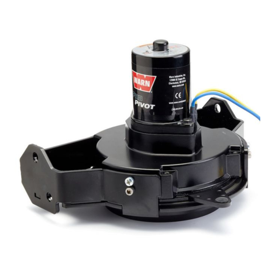
PRO-PIVOT
Part Number: 88700
1
CAUTION
88783A3
Advertisement
Table of Contents

Related Manuals for Warn 88700


Summary of Contents for Warn 88700
-
Page 1: Installation Instructions
This information alerts you to potential hazards that could hurt you or others. It is not possible to warn you about all potential hazards associated with this product, you must use your own good judgment. - Page 2 The Pro-Pivot is capable of rotating the blade 28 degrees in each direction from center. • Do not excessively load plow, bracket, and pivot. ©2012 Warn Industries, Inc.WARN® and the WARN logo are trademarks of Warn Industries Inc. 88783A3...
-
Page 3: Table Of Contents
Please use the recommended torque specifications when assembling this product unless otherwise specified in the instructions. M8 12 lb. ft. (17 N-m) M10 31 lb. ft. (42 N-m) M12 60 lb. ft. (81N-m) M16 100 lb. ft (135 N-m) ©2012 Warn Industries, Inc.WARN® and the WARN logo are trademarks of Warn Industries Inc. 88783A3... - Page 4 2. Remove the blade from the tube base by unscrewing the two bolts. See Figure 2. Figure 2 3. Remove shoulder screw to remove the plow lever as shown in Figure 3. Figure 3 ©2012 Warn Industries, Inc.WARN® and the WARN logo are trademarks of Warn Industries Inc. 88783A3...
-
Page 5: Installation
The Pro-Pivot then mounts onto the push tube assembly, replacing top retaining plate and bearing plate. Figure 6 ©2012 Warn Industries, Inc.WARN® and the WARN logo are trademarks of Warn Industries Inc. 88783A3... - Page 6 Figure 8 Figure 9. 10. Insert motor wiring into conduit and install cable tie around motor in location shown in Figure 10. Figure 9 Figure 10 ©2012 Warn Industries, Inc.WARN® and the WARN logo are trademarks of Warn Industries Inc. 88783A3...
-
Page 7: Switch Mounting
• Before securing the switch cable with tie wraps, make sure that the handlebars have full range of motion. Winch Switch New Hardware Use a test light to locate a suitable wire. Figure 13 ©2012 Warn Industries, Inc.WARN® and the WARN logo are trademarks of Warn Industries Inc. 88783A3... -
Page 8: Contactor Mounting
CAP SCREW M8 HEX HEAD CAP SCREW CABLE TIE SWITCH BRACKET LIMIT SWITCH LIMIT SWITCH MARKED M8 NYLON WITH "LEFT" TAG HEX NUT Figure 15 ©2012 Warn Industries, Inc.WARN® and the WARN logo are trademarks of Warn Industries Inc. 88783A3... -
Page 9: System Check
Slow Operation confirm limit switches are plugged into control harness • Will not go in opposite direction: limit switches installed incorrectly confirm control harness is grounded bullet connectors in wrong order ©2012 Warn Industries, Inc.WARN® and the WARN logo are trademarks of Warn Industries Inc. 88783A3... -
Page 10: Maintenance/Care
3. 3. Call an authorized WARN Service center from the list provided on the back of the warranty sheet included with the product. When calling, please have the following information available: Pro-Pivot model number and purchase date, make, model and year of ATV. -
Page 11: Service Kits
CARELESS INSTALLATION AND OPERATION CAN RESULT IN SERIOUS INJURY OR EQUIPMENT DAMAGE. READ AND UNDERSTAND ALL SAFETY PRECAUTIONS AND OPERATING INSTRUCTIONS BEFORE INSTALLING AND OPERATING THIS PRODUCT. ©2012 Warn Industries, Inc.WARN® and the WARN logo are trademarks of Warn Industries Inc. 88783A3...
Need help?
Do you have a question about the 88700 and is the answer not in the manual?
Questions and answers