Advertisement
Table of Contents
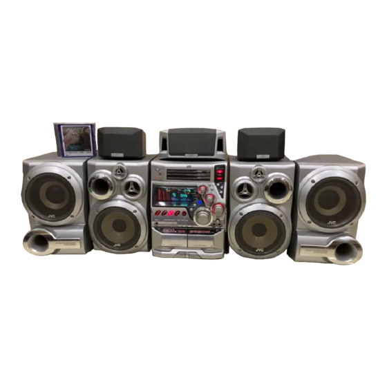
SERVICE MANUAL
COMPACT COMPONENT SYSTEM
(SP-XDVB10)
MAIN
Contents
Safety precautions
Preventing static electricity
Precautions for service
Important for laser products
Disassembly method
Adjustment method
(SP-XCDVB10)
(SP-XSDVB10)
CENTER
REAR
(SP-WDVB10)
(CA-MXDVB10)
SUBWOOFER
1-2
1-3
1-4
1-5
1-6
1-26
COPYRIGHT
2002 VICTOR COMPANY OF JAPAN, LTD.
(SP-WDVB10)
SUBWOOFER
until TOC read
US ------------- Singapore
UX ---------- Saudi Arabia
UN -------------------Asean
(SP-XDVB10)
MAIN
1-34
1-34
1-35
1-36~70
No.21120
Sep. 2002
Advertisement
Table of Contents

Related Manuals for JVC MX-DVB10


Summary of Contents for JVC MX-DVB10
-
Page 1: Table Of Contents
MX-DVB10 SERVICE MANUAL COMPACT COMPONENT SYSTEM MX-DVB10 Area suffix US ------------- Singapore UX ---------- Saudi Arabia UN -------------------Asean (SP-XCDVB10) (SP-XSDVB10) (SP-XSDVB10) REAR CENTER REAR (SP-XDVB10) (SP-WDVB10) (SP-WDVB10) (CA-MXDVB10) (SP-XDVB10) MAIN SUBWOOFER SUBWOOFER MAIN Contents Safety precautions Maintenance of laser pickup... -
Page 2: Mx-Dvb10
MX-DVB10 1. This design of this product contains special hardware and many circuits and components specially for safety purposes. For continued protection, no changes should be made to the original design unless authorized in writing by the manufacturer. Replacement parts must be identical to those used in the original circuits. Services should be performed by qualified personnel only. - Page 3 MX-DVB10 Preventing static electricity 1. Grounding to prevent damage by static electricity Electrostatic discharge (ESD), which occurs when static electricity stored in the body, fabric, etc. is discharged, can destroy the laser diode in the traverse unit (optical pickup). Take care to prevent this when performing repairs.
- Page 4 MX-DVB10 Precautions for service Handling of Traverse Unit and Laser Pickup 1. Do not touch any peripheral element of the pickup or the actuator. 2. The traverse unit and the pickup are precision devices and therefore must not be subjected to strong shock.
- Page 5 MX-DVB10 Important for laser products 5.CAUTION : If safety switches malfunction, the laser is able 1. CLASS 1 LASER PRODUCT to function. 2. DANGER : Invisible laser radiation when open and inter 6.CAUTION : Use of controls, adjustments or performance of lock failed or defeated.
- Page 6 MX-DVB10 Disassembly method Metal cover <Main body> Removing the metal cover (See Fig.1 to 3) Remove the six screws marked A on the back of the body. Remove the two screws marked B on both sides of the body. Remove the metal cover from the body by lifting the rear part of the cover.
- Page 7 MX-DVB10 Removing the DVD changer mechanism assembly (See Fig.5 to 6) Prior to performing the following procedures, remove the metal cover and the tuner board. Front panel assembly Disconnect the card wire from the connectors CN540, CN541 and CN542 on the main board.
- Page 8 MX-DVB10 Removing the front panel assembly Main board CN513 Tie band (See Fig.7 to 11) Prior to performing the following procedures, remove CN500 the metal cover, the tuner board and the DVD changer mechanism assembly. CN505 Remove the plastic rivet attaching the main board.
- Page 9 MX-DVB10 Removing the rear cover / rear panel Rear panel (See Fig.12 to 15) Prior to performing the following procedures, remove the metal cover, the tuner board and the DVD changer mechanism assembly. Remove the screw marked H attaching the rear cover on the back of the body.
- Page 10 MX-DVB10 Front panel assembly Removing the power supply board (See Fig.17) Prior to performing the following procedures, remove Power supply board the metal cover, the tuner board, the DVD changer mechanism assembly, the rear panel and the power cord. CN219...
- Page 11 MX-DVB10 Removing the AV output board AV output board (See Fig.22, 23) Prior to performing the following procedures, remove the metal cover, the tuner board, the DVD changer Fan bracket mechanism assembly, the rear panel, the amplifier CN705 board (1,2) and the power supply board.
- Page 12 MX-DVB10 Removing the main board Main board (See Fig.26, 27) CN500 Prior to performing the following procedures, remove Transformer the metal cover, the tuner board, the DVD changer CN505 board mechanism assembly, the rear panel, the power supply board, the amplifier board and AV output CN510 board.
-
Page 13: Front Panel Assembly
MX-DVB10 Head amplifier <Front panel assembly> & mechanism control board Prior to performing the following procedures, remove the metal cover, the DVD changer mechanism CN306 assembly and front panel assembly. Removing the cassette mechanism assembly (See Fig.29) Disconnect the card wire from the connector CN306 on the head amplifier &... - Page 14 MX-DVB10 Removing the DVD eject board DVD eject board (See Fig.33) FW915 (Soldered) Remove the three screws marked R attaching the DVD eject board. If necessary, unsolder FW915 on the DVD eject board. Fig.33 Preset / tuning switch board Removing the preset / tuning switch board (See Fig.34, 35)
- Page 15 MX-DVB10 Joints a < Main Speaker > Removing the front cover (See Fig.1, 2) Remove the four screws marked A on the front of the body. Front cover Remove the front cover from the four holders marked a that are fixing the front cover.
-
Page 16: Center Speaker
MX-DVB10 < Subwoofer > Front cover Removing the front cover (See Fig.3, 4) Remove the four screws D on the front of the body. Remove the front cover from the four holders marked b that are fixing the front cover. - Page 17 MX-DVB10 DVD Changer Mechanism Removing the DVD Servo control board (See Fig.1) Remove the metal cover. Remove the DVD changer mechanism assembly. From bottom side the DVD changer mechanism assembly, remove the one screw 1 retaining the DVD servo control board.
- Page 18 MX-DVB10 Stopper Check whether the lifter unit stopper has been caught into the hole at the section "E" of DVD tray assembly as shown in Fig.5. Make sure that the driver unit elevator is positioned as shown in Fig.6 from to the second or fifth hole on the left side face of the DVD Traverse mechanism assembly.
- Page 19 MX-DVB10 Cams R1, R2 assembly Removing the DVD mechanism assembly (See Fig.10) While turning the cams R1 and R2 assembly in the arrow direction "H" . align the shaft "I" of the DVD mechanism assembly to the position shown in Fig.10.
- Page 20 MX-DVB10 Motor L Motor R Removing the actuator motor board (See Fig.14, 15) Absorb the four soldered positions "M" of the right and left motors with a soldering absorber (See Fig.14). Remove the two screws 7 retaining the actuator motor board (See Fig.14).
- Page 21 MX-DVB10 Removing the actuator motor and belt Gear bracket (See Fig.19~22) Remove the two screws 10 retaining the gear bracket (See Fig.19). While pressing the pawl "P" fixing the gear bracket in the arrow direction, remove the gear bracket Pulley gear (See Fig.19).
- Page 22 MX-DVB10 Slit washer Removing the cams R1/R2 assembly and cam gear L (See Fig.23) Cam R2 Slit washer Remove the slit washer fixing the cams R1 and R2 assembly. Cam gear L By removing the two pawls "S" fixing the cam R1, separate R2 from R1.
-
Page 23: Cassette Mechanism Section
MX-DVB10 < Cassette Mechanism Section > Cassette mechanism Removing the Playback, Recording and Eraser Heads (See Fig.1~3) 1. While shifting the trigger arms seen on the right side of the head mount in the arrow direction, turn Flywheel R the flywheel R in counterclockwise direction until the head mount has gone out with a click (See Fig. - Page 24 MX-DVB10 Removing the Head Amplifier. and Mechanism Control P.C. Board (See Fig. 4) Head amplifier & 1. Remove the cassette mechanism assembly. mechanism control board 2. After turning over the cassette mechanism assembly, remove the five screws "A" retaining the head amp. and mechanism control P.C.
- Page 25 MX-DVB10 Removing the Capstan Motor (See Fig. 8) Capstan motor From the joint bracket, remove the two screws "C" retaining the capstan motor. Joint bracket Removing the Flywheel (See Fig. 9,10) 1. Remove the head amp. and mechanism control P.C. Board.
- Page 26 MX-DVB10 Adjustment method Measurement instruments required for adjustment Radio input signal 1. Low frequency oscillator, AM modulation frequency : 400Hz This oscillator should have a capacity to output 0dBs Modulation factor : 30% with a termination of 600ohm impedance at an FM modulation frequency : 400Hz oscillation frequency of 50Hz-20kHz.
- Page 27 MX-DVB10 Arrangement of adjusting positions Cassette mechanism section (Mechanism A section) Cassette mechanism section (Back side) Head azimuth Head azimuth adjusting screw adjusting screw (Reverse side) (Forward side) Head azimuth Head azimuth Playback, recording and eraser adjusting screw adjusting screw...
- Page 28 MX-DVB10 Tape recorder section Adjusting Items Measurement Standard Measurement method positions conditions values Confirmation Adjust the head Test tape Maximum 1. Playback the test tape VT703L (10kHz). of head angle azimuth screw :VT703L (10kHz) output 2. With the playback mechanism or recording &...
- Page 29 MX-DVB10 Electrical performance Adjusting Items Measurement Standard Measurement method positions conditions values Adjustment of AC-225 *Mode : Forward or 1. With the recording and playback mechanism, recording bias :4.20 A reverse mode load the test tapes (AC-225 to TYP ), and set the...
- Page 30 MX-DVB10 DVD section TEST MODE FOR DVD and to INITIALISE THE DVD UNIT BOARD a) Insert A/C Power Cord b) At standby mode press Stop Button and CANCEL/DEMO button. Wait 4 seconds for the display of " TEST VERSION REGION " i.e. TEST JC 1 c) Press the 'ENTER' button on remocon.
- Page 31 MX-DVB10 Integrated wiring for adjustment Extension cord (See Fig.1 to 3) QUQ605-4040AJ Place a board on top of the unit and put the changer on it. Then carry out the wiring of the main unit. Connect a extension cable to the traverse mechanism for adjustment and then connect them to the changer.
- Page 32 MX-DVB10 Display of "Laser current value and" "Jitter value" "Laser current value" and "Jitter value" are displayed on the FL display by the undermentioned method. Please refer to the failure diagnosis. 1) Take out the disc and close the tray.
- Page 33 MX-DVB10 For Jitter value The jitter value is displayed by the hexadecimal number and please refer to the conversion table below. If the indication value is 11 or less, it can be judged by this simple checking method that the signal read precision of the set is satisfactory.
-
Page 34: Maintenance Of Laser Pickup
MX-DVB10 Maintenance of laser pickup Replacement of laser pickup (1) Cleaning the pick up lens Before you replace the pick up, please try to Turn off the power switch and, disconnect the clean the lens with a alcohol soaked cotton power cord from the ac outlet. -
Page 35: Flow Of Functional Operation
MX-DVB10 Flow of functional operation until TOC read Check Point Slider turns REST Play Key Power ON Confirm that the voltage at the pin29 SW ON. of CN101 (TP28) is "H"\"L"\"H". Automatic tuning of TE offset Check that the voltage at the... -
Page 36: Description Of Major Ics 1-36~70
MX-DVB10 Description of major ICs MN101C35DEG (IC810) : System control & FL driver 1. Pin layout 2. Pin function Symbol Function Pin No. SYSOUT DVD signal output SYSIN DVD signal input DVDCLK DVD signal clock DATAOUT Tuner signal output DATAIN... - Page 37 MX-DVB10 Symbol Function Pin No. Chip enable for EXT.IC EXIT1 Chip enable for SLC control SLCCE DVD reset DVDRST FL drive control FL drive control FL drive control FL drive control FL drive control FL drive control FL drive control...
- Page 38 MX-DVB10 MN103S13BDA (IC301) : Optical disc controller 1. Pin layout HDD15 SBCK HDD0 HDD14 HDD1 PVDD HDD13 PVSS HDD2 OSCO1 HDD12 OSCI1 HDD3 LRCK HDD11 BLKCK HDD4 IPFLAG HDD10 DACCLK DACLRCK HDD5 DACDATA HDD9 NTRON MN103S13BDA HDD6 JMPINH HDD8 IDHOLD...
- Page 39 MX-DVB10 3. Pin function (1/3) Symbol Description Pin No. ATAPI Data HDD15 ATAPI Data HDD0 ATAPI Data HDD14 Power supply 3V ATAPI Data HDD1 ATAPI Data HDD13 ATAPI Data HDD2 Connect to GND ATAPI Data HDD12 Power supply 2.7V ATAPI Data...
- Page 40 MX-DVB10 3. Pin function (2/3) Symbol Description Pin No. CPUADR5 System control address CPUADR4 System control address CPUADR3 System control address CPUADR2 System control address CPUADR1 System control address Connect to GND CPUADR0 System control address System control chip select...
- Page 41 MX-DVB10 3. Pin function (3/3) Symbol Description Pin No. OSCO1 Oscillation output terminal 16.9MHz Power supply 3V PVSS Connect to GND PVDD Power supply 3V Terminal master polarity switch input CIRC-RAM,OVER/UNDER Interruption Connect to GND SBCK Clock output for sub code,serial input...
- Page 42 MX-DVB10 MN101C49GEH 1 (IC500) : AV decorder 1. Pin layout 2. Pin function Pin No. Symbol Function VREF Reference voltage No connect No connect No connect NTSEL NTSC/PAL selection POWER SW No connect SHUT1 No connect KEY1-5 No connect KEY6-10...
- Page 43 MX-DVB10 Pin No. Symbol Function CHCK Channel clock DVDOUT DVD data output DVDIN DVD data input DVDCLK DVD clock DVDBSY Busy bus for DVD No connect No connect No connect No connect No connect Fanction SW control Fanction SW control...
- Page 44 MX-DVB10 ZIVA-4.1 PA2 (IC501) : AV decoder 1. Pin layout 2. Pin function (1/5) Pin No. Symbol Description Read strobe input Read/write strobe input Power supply terminal 3.3V Transfer not complete / data acknowledge. WAIT Active LOW to indicate host initiated transfer is complete.
- Page 45 MX-DVB10 2. Pin function (2/5) Pin No. Symbol Description Connect to ground Non connect Non connect Non connect Non connect Non connect Programmable I/O terminal PIO0 Connect to ground Power supply terminal 3.3V Programmable I/O terminal PIO1 Programmable I/O terminal...
- Page 46 MX-DVB10 2. Pin function (3/5) Pin No. Symbol Description SDRAM address MADDR6 SDRAM address MADDR5 Power supply terminal 2.5V Connect to ground SDRAM address MADDR4 SDRAM write enable Active LOW SDRAM column address SD-CAS Power supply terminal 3.3V Connect to ground...
- Page 47 MX-DVB10 2. Pin function (4/5) Pin No. Symbol Description Connect to ground Non connect VSS_DAC Connect to ground for analog video DAC VSS_VIDEO Connect to ground for analog video DAC video output format : CVBS. Macrovision encoded CVBS VDD_DAC Power supply terminal for analog video DAC...
- Page 48 MX-DVB10 2. Pin function (5/5) Pin No. Symbol Description DVD parallel compressed data from DVD DSP. or CD-G clock indicating DVD-DATA7/CDG-SCLK sub code data clock input or output VDACK In synchronous mode, bitstream data acknowledge. Asserted when DVD data is valid.Polarity is programmable...
- Page 49 MX-DVB10 AN7345K (IC302) : REC/PRE Amp. 1. Pin layout / Block diagram REPPLE Source CTRL CTRL 2. Pin function Pin No. Function CH1 Playback amplifier input(1) CH1 Playback amplifier input(2) CH1 Playback amplifier negative feedback CH1 Playback amplifier output CH1 Equalizer input...
- Page 50 MX-DVB10 MN67706ZY (IC201) : Auto digital servo controller 1. Pin layout CHCK40 TSTSG DAT3 DAT2 SYSCLK DAT1 OFTR DAT0 33VDD 33VSS 33VSS 33VDD FBAL TBAL XRESET TGBAL AVSS ROUT CPUIRQ LOUT MN67706ZY CPUCLK AVDD CPUDTIN JLINE CPUDTOUT DBALO MONA VCOF...
- Page 51 MX-DVB10 2. Pin function (2/3) Pin No. Symbol Function VFOSHORT VFO short output AVDD Apply 3.3V(For analog circuit) HPFIN Pull-up to VHALF HPFOUT Connect to TP208 AVSS Ground(For analog circuit) LPFIN Pull-up to VHALF LPFOUT Not use CMPIN Connect to TP210...
- Page 52 MX-DVB10 2. Pin function (3/3) Pin No. Symbol Function 33VSS Ground (For I/O) 33VDD Apply 3.3V (For I/O) Digital audio interface XRESET Reset input (System control) Servo DSC serial I/F chip select (System control) CIRC serial I/F chip select (System control)
- Page 53 MX-DVB10 AN8702FH (IC101) : Frontend processor 1. Pin layout RFINN PC01 RFINP TESTSG PC02 AGCO TGBAL AGCG TBAL PEAK FBAL BOTTOM AN8702FH POFLT RFENV DTRD IDGT OFTR STANDBY DCRF VCC3 STDI RFOUT RSEL RFDIFO JLINE GND3 2. Pin function Symbol...
- Page 54 MX-DVB10 BA3838F-X (IC560) : Stero A/D converter 1. Pin layout 2. Bloc k diagram Pin No. Symbol Function Power supply MICIN Microphone mixing input LOUT Channel L output Accepts signal from the key controller Output signal to the key controller...
- Page 55 MX-DVB10 BA15218 (IC511~IC516, IC531~IC536) : Operation amplifier 1. Pin layout OUT1 -IN1 OUT2 +IN1 -IN2 +IN2 2. Block diagram OTHER Q114 OUTPUT BA3126N (IC301) : R/P Switch C O N T . NAX0393-001 (IC502) : 27MHz Oscilator 1. Pin layout...
- Page 56 MX-DVB10 BU9253AS (IC902) : LPF / Echo Mix. 1. Pin layout / Block diagram MUTE ECHO VR BIAS ADINT IN DAINT IN ADINT OUT DAINT OUT ADLPF OUT DALPF IN ADLPF IN DALPF OUT MIX IN MIX OUT 2. Pin function Descriptions Pin No.
- Page 57 MX-DVB10 KM416S1120DT-G8 (IC504, IC505) : 16M SDRAM 1. Pin layout DQ15 DQ14 VSSQ VSSQ DQ13 DQ12 VDDQ VDDQ DQ11 DQ10 VSSQ VSSQ VDDQ VDDQ LDQM N.C/RFU UDQM A10/AP 2. Pin function Pin No Symbol Function Pin No Symbol Function Connect to GND...
- Page 58 MX-DVB10 LA1838 (IC1) : FM AM IF Amp. & Detector, FM MPX Decoder 1. Block diagram DECODER RF.AMP ANIT-BIRDIE MUTE BUFF STEREO P-DET AM IF PILOT 384KHz COMP S-METER AM/FM S-CLRVE S-METER IF-BUFF TUNING STEREO DRIVE DRIVE FM IF 2. Pin function...
- Page 59 MX-DVB10 LC72136N (IC2) : PLL Frequency synthesizer 1. Pin layout FM/AM LPFOUT LPFIN CLOCK FM/ST/VCO FMIN AM/FM AMIN IFCONT SDIN IFIN 2. Block diagram Phase Reference Detector Driver Charge Pump Swallow Counter Swallow Counter 1/16,1/17 4bit 1/16,1/17 4bit Unlock Detector...
- Page 60 MX-DVB10 LC75342M-X (IC522, IC523) : E. volume 1. Pin layout LVref CONTROL CIRCUIT LOGIC CIRCUIT INTERFACE CONTROL RVref CIRCUIT 3. Pin function Function Function Symbol Symbol Serial data and clock input for IC control Input signal connections Chip enable Input signal connections...
- Page 61 MX-DVB10 LC75345M-X (IC521) : Input selector 1. Pin layout 2. Bloc k diagram LVref CONTROL CIRCUIT LOGIC CIRCUIT INTERFACE CONTROL CIRCUIT RVref 3. Pin function Function Function Symbol Symbol Serial data input VREF 0.5 X VDD voltage genration Chip enable...
- Page 62 MX-DVB10 LV1100 (IC550) : Karaoke mic echo surround amp. 1. Pin layout 2. Block diagram EFECT VOL 5KX2 DC-CUT L.P.F. 12PIN SRAM 12K 20PIN 19PIN 18PIN D/A CONV. A/D CONV. 7KHZ L.P.F DC-CUT 3. Pin function Symbol Function Pin No.
- Page 63 MX-DVB10 M56788FP-M (IC271) : Traverse mechanism driver 1. Pin layout REG+ CH3IN REGB OUT3 IN1+ IN3- VBS1 VBS2 IN1- OUT1 VM1- IN3+ VM1+ VM3- VM3+ VM2+ VM2- VM4+ VM4- OUT2 VM5+ VM5- IN2- IN2+ OUT5 MUTE1 IN5- MUTE2 IN5+ SS.GND...
- Page 64 MX-DVB10 MN102L62GEJ (IC401) : Unit CPU 1. Pin layout y 2. Pin function Function Symbol Symbol Function Pin No. Pin No. Micon wait signal input FGIN WAIT Read enable Spindle muting outout to IC251 Serial enable signal for ADSC SPMUTE...
- Page 65 MX-DVB10 MM3023DN-X (IC1, IC102) : Switching regulator 1. Pin layout 1. Block diagram Vref Current Limit 3. Pin function Pin No. Symbol Function Connect to GND Power supply VOUT Regulator output No connect Output voltage on/off control BR93LC66F-X (IC403) : EEPROM 1.
- Page 66 MX-DVB10 MN35505 (IC501, IC502, IC503) : DAC 1. Pin layout 2. Pin function Symbol Function Pin No. Control signal for DAC Digital data input LRCK L and R clock for DAC Bit clock for DAC Control signal for DAC DVDD2...
- Page 67 MX-DVB10 MR27V1602EM (IC402) : 16M ROM 1. Pin layout BYTE/Vpp D15/A-1 2. Pin function Pin No Symbol Function Pin No Symbol Function Power supply Address input Data output Data output Address input Address input Data output Address input Data output...
- Page 68 MX-DVB10 STK412-090 (IC701) : Operation amplifier 1. Pin layout STK412-000 2. Block diagram 18 17 TR41 Compartor TR12 TR11 TR16 TR19 TR14 TR13 TR18 TR10 TR20 TR15 Compartor TR17 TR51 9 8 11 10 STK402-040 (IC752) : Operation amplifier 1. Pin layout STK402-050 2.
- Page 69 MX-DVB10 TC7SH08FU-X (IC311, 312) : Timing control TA8409S (IC802, 803) : Motor driver 1. Pin layout 1.Pin layout IN B IN A 2. Pin function INPUT OUTPUT MODE OUT Y OUT1 OUT2 MOTOR STOP CW/CCW CCW/CW BRAKE TC74VHC00FT-X (IC322,IC503) : Write timing control 1.
- Page 70 MX-DVB10 TC7WH74FU-X (IC321) : Clock buffer TC7W125FU-X (IC412) : Buffer 1. Pin layout 1. Pin layout (TOP VIEW) 2. Block diagram 2. Block diagram STK402-230 (IC321) : Power amp 1. Pin layout STK402-230 8 +Vcc 2. Block diagram PRE+Vcc TR11...
- Page 71 MX-DVB10 < M E M O > 1-71...
- Page 72 MX-DVB10 VICTOR COMPANY OF JAPAN, LIMITED AUDIO & COMMUNICATION BUSINESS DIVISION PERSONAL & MOBILE NETWORK BUSINESS UNIT. 10-1,1chome,Ohwatari-machi,Maebashi-city,371-8543,Japan Printed in Japan (No.21120) 200209...
-
Page 73: Area Suffix
MX-DVB10 PARTS LIST [ MX-DVB10 ] * All printed circuit boards and its assemblies are not available as service parts. Area suffix US ---------------------- Singapore UX ------------------- Saudi Arabia UN ----------------------------Asean - Contents - 3- 3 Exploded view of general assembly and parts list (Block No.M1) 3- 6 Speaker assembly and parts list SP-XDVB10 (Block No.M7) - Page 74 MX-DVB10 < M E M O >...
- Page 75 MX-DVB10 Exploded view of general assembly and parts list Block No. 104 109 AV output board 51 47 Display system control board Tuner board Operation switch board Amplifier board(1) Preset / tuning Main board switch board Amplifier board(2) DVD servo...
- Page 76 MX-DVB10 MX-DVB10 Parts list (General assembly) Parts list (General assembly) Block No. M1MM Block No. M1MM Item Parts number Parts name Q'ty Description Area Item Parts number Parts name Q'ty Description Area GV10057-007A FRONT PANEL LV41363-002A HOLDER GV40246-001A FOOT SPACER...
- Page 77 MX-DVB10 Parts list (General assembly) Block No. M1MM Item Description Parts number Parts name Q'ty Area QAR0177-001 1 SUPPLIER NIDEC QYSBSG3010Z T.SCREW 2 C3 & STAY BRKT QYSBSGY3008E SPECIAL SCREW 1 REAR PNL/CHAS.B SPECIAL SCREW 1 REAR PNL/AUX QYSBSGY3008E QYSBSGY3008E SPECIAL SCREW 4 REAR PNL/H.SINK...
- Page 78 MX-DVB10 Speaker assembly and parts list Block No. SP-XDVB10 Parts list (Speaker assembly) SP-XDVB10 Block No. M7MM Item Description Parts number Parts name Q'ty Area SP BOX ASSY(L) MXDVB10K-SPBOXL MXDVB10K-SPBOXR SP BOX ASSY(R) 199733350151 FRONT PANEL(R) FRONT PANEL(L) 199733350152 135604161053...
- Page 79 MX-DVB10 Speaker assembly and parts list Block No. SP-WDVB10 Parts list (Speaker assembly) SP-WDVB10 Block No. M8MM Item Description Parts number Parts name Q'ty Area MXDVB10K-SPKSBL SP BOX ASSY(L) MXDVB10K-SPKSBR SP BOX ASSY(R) FRONT PANEL(R) 199733350153 199733350154 FRONT PANEL(L) 135604161053...
- Page 80 MX-DVB10 DVD mechanism assembly and parts list Block No. FXL-V62-1M Grease & Three bond Grease & Three bond = EBS0006-013B =CFD-4007ZY2 =946P =1401B Relay board 65.2 12.0 0.2mm...
- Page 81 MX-DVB10 Parts list (DVD mechanism) Block No. MJMM Item Parts number Parts name Q'ty Description Area LV20638-201A MECHA BASE LV20635-001A SHAFT HOLDER QYSBST2606M T.SCREW FXL-V6SPSV-2C SP.MOTOR ASSY QUM193-08B2B2 PARA RIBON WIRE QYSBST2606M T.SCREW 1 FOR S.BASE&M.BA DVD PICK UP OPTIMA-2010B1...
- Page 82 MX-DVB10 DVD changer mechanism assembly and parts list Block No. FLM-C5-3M Grease = EM-30L = EBS0006-009B = FL-7750 FIG B FIG C FIG B FIG C Opposite side the same. FIG A FIG A CAUTION The axes of each gear...
- Page 83 MX-DVB10 Parts list (DVD changer mechanism) Block No. MKMM Item Parts number Parts name Q'ty Description Area VKS1144-004 CHASSIS VKS3698-003 TRAY GUIDE VKS5532-003 PULLEY GEAR VKB3000-164 BELT VKS5505-003 GEAR B VKS5506-002 GEAR C VKS5507-002 CROSS GEAR U VKS5508-002 CROSS GEAR L...
- Page 84 MX-DVB10 Cassette mechanism assembly and parts list Block No. SLC-W101M Cassette switch board Head amplifier & mechanism control board 3-12...
- Page 85 MX-DVB10 Parts list (Cassette mechanism) Block No. MPMM Item Description Parts number Parts name Q'ty Area CHASSIS B.ASS'Y VKS1165-00K VKR4749-004 IDLE PULLEY LV42026-001A SHAFT REEL GEAR VKS2274-002 B.T. SPRING VKW5286-002 VKS5559-001 PLAY IDLE GEAR VKS5597-00B BLIND EARTH SPRING LV42013-001A SLC-P1SVM...
- Page 86 MX-DVB10 Grease point =JC-525 Grease =UD-24 =LEN-320M =MOBIL-1 B mecha A mecha 3-14...
- Page 87 MX-DVB10 Front view Rear view B - B (2/1) C - C (2/1) D - D (2/1) E - E (5/1) A - A (2/1, 2 places) (Dipping) 3-15...
- Page 88 MX-DVB10 Electrical parts list (Power board) Block No. 01 Item Parts number Parts name Remarks Area Item Parts number Parts name Remarks Area C 201 QFZ0212-104Z MM CAPACITOR .10MF C 344 QETN1HM-106Z E CAPACITOR 10MF 20% 50V C 202 QFZ0212-104Z MM CAPACITOR .10MF...
- Page 89 MX-DVB10 Electrical parts list (Power board) Block No. 01 Item Parts number Parts name Remarks Area Item Parts number Parts name Remarks Area CN705 QGA2501F1-02 CONNECTOR IC752 STK402-040 CN772 QGB2510K2-06 CONNECTOR J 280 QNB0107-001 SPK TERMINAL D 201 1N5402M-20 DIODE...
- Page 90 MX-DVB10 Electrical parts list (Power board) Block No. 01 Item Remarks Item Parts number Parts name Remarks Area Parts number Parts name Area R 260 QRE141J-272Y C RESISTOR 2.7K 5% 1/4W R 706 QRJ146J-821X UNF C RESISTOR 820 5% 1/4W...
- Page 91 MX-DVB10 Electrical parts list (Power board) Block No. 01 Item Parts number Parts name Remarks Area R 769 QRL01DJ-821X OMF RESISTOR 820 5% 1/1W R 770 QRL01DJ-821X OMF RESISTOR 820 5% 1/1W R 774 QRE141J-333Y C RESISTOR 33K 5% 1/4W...
- Page 92 MX-DVB10 Electrical parts list (Main board) Block No. 02 Item Remarks Item Parts number Parts name Remarks Area Parts number Parts name Area C 402 QCZ0202-155Z ML C CAPACITOR 1.5MF C 548 EETC1AM-227ZJC E CAPACITOR C 404 QCZ0202-155Z ML C CAPACITOR 1.5MF...
- Page 93 MX-DVB10 Electrical parts list (Main board) Block No. 02 Item Remarks Item Parts number Parts name Remarks Area Parts number Parts name Area C 660 EETC1CM-476ZJC E CAPACITOR C1563 QDGB1HK-103Y C CAPACITOR C 661 EETC1CM-106ZJC E CAPACITOR C1564 EETC0JM-477ZJC C CAPACITOR...
- Page 94 MX-DVB10 Electrical parts list (Main board) Block No. 02 Item Parts number Parts name Remarks Area Item Parts number Parts name Remarks Area J 502 QNS0009-001 3.5 JACK R 411 QRE141J-101Y C RESISTOR 100 5% 1/4W K 401 NQR0428-002X F.BEADS...
- Page 95 MX-DVB10 Electrical parts list (Main board) Block No. 02 Item Parts number Parts name Remarks Area Item Parts number Parts name Remarks Area R 532 NRSA63J-103X MG RESISTOR R 619 NRSA63J-563X MG RESISTOR R 533 NRSA63J-683X MG RESISTOR R 620...
- Page 96 MX-DVB10 Electrical parts list (Main board) Block No. 02 Item Parts number Parts name Remarks Area Item Parts number Parts name Remarks Area R1521 NRSA63J-183X MG RESISTOR SP 10 VYSA1R3-049 SPACER R1522 NRSA63J-183X MG RESISTOR SP 11 VYSA1R3-049 SPACER R1523...
- Page 97 MX-DVB10 Electrical parts list (Front board) Block No. 03 Item Remarks Item Remarks Parts number Parts name Area Parts number Parts name Area C 233 QFLC1HJ-104Z M CAPACITOR .10MF 5% 50V C1064 QCBB1HK-151Y C CAPACITOR 150PF 10% 50V C 801...
- Page 98 MX-DVB10 Electrical parts list (Front board) Block No. 03 Item Parts number Parts name Remarks Area Item Parts number Parts name Remarks Area L 805 QQL244K-100Z INDUCTOR R 845 QRE141J-102Y C RESISTOR 1.0K 5% 1/4W L 806 QQL244K-100Z INDUCTOR R 846...
- Page 99 MX-DVB10 Electrical parts list (Front board) Block No. 03 Item Parts number Parts name Remarks Area Item Parts number Parts name Remarks Area R 931 QRE141J-222Y C RESISTOR 2.2K 5% 1/4W R1062 QRE141J-123Y C RESISTOR 12K 5% 1/4W R 932...
- Page 100 MX-DVB10 Block No. 04 Electrical parts list (Power supply board) Item Remarks Parts number Parts name Area C 254 QFZ9075-683 M CAPACITOR .068MF C 381 QDGB1HK-102Y C CAPACITOR C 382 QDGB1HK-102Y C CAPACITOR C 383 QDGB1HK-102Y C CAPACITOR C 384...
- Page 101 MX-DVB10 Electrical parts list (DVD servo board) Block No. 05 Item Parts number Parts name Remarks Area Item Parts number Parts name Remarks Area NCB31CK-104X C CAPACITOR C 228 NCB31HK-102X C CAPACITOR NEA70JM-226X E CAPACITOR C 237 NCB31CK-104X C CAPACITOR...
- Page 102 MX-DVB10 Electrical parts list (DVD servo board) Block No. 05 Item Parts number Parts name Remarks Area Item Parts number Parts name Remarks Area C 327 NEA70GM-107X E CAPACITOR C 548 NCB31CK-104X C CAPACITOR C 341 NCB31CK-104X C CAPACITOR C 556...
- Page 103 MX-DVB10 Block No. 05 Electrical parts list (DVD servo board) Item Parts number Parts name Remarks Area Item Parts number Parts name Remarks Area NRSA63J-100X MG RESISTOR R 238 NRSA63J-221X MG RESISTOR R 103 NRS125J-270X MG RESISTOR R 239 NRSA63J-221X...
- Page 104 MX-DVB10 Electrical parts list (DVD servo board) Block No. 05 Item Remarks Item Remarks Parts number Parts name Area Parts number Parts name Area R 347 NRSA63J-102X MG RESISTOR R 541 NRSA63J-0R0X MG RESISTOR R 348 NRSA63J-102X MG RESISTOR R 542...
- Page 105 MX-DVB10 Electrical parts list (Tuner board) Block No. 06 Item Remarks Item Remarks Parts number Parts name Area Parts number Parts name Area NCB21HK-223X C CAPACITOR IC 2 LC72136N NCB21HK-103X C CAPACITOR QNB0014-001 ANT TERMINAL EETC1CM-106ZJC E CAPACITOR QQR0796-002 COIL BLOCK...
- Page 106 MX-DVB10 Electrical parts list (DVD traverse board) Block No. 07 Electrical parts list (DVD changer board) Block No. 08 Item Remarks Item Parts number Parts name Remarks Area Parts number Parts name Area C 801 QEKC1AM-107Z E.CAPACITOR 100MF 20% 10V...
- Page 107 MX-DVB10 Electrical parts list (Head amplifier & mechanism control board) Block No. 10 Item Remarks Item Remarks Parts number Parts name Area Parts number Parts name Area CN301 QGF1205F1-06 CONNECTOR A HEAD D3302 1SR139-400-T2 SI DIODE CN302 QGF1205F1-06 CONNECTOR B HEAD D3307 DZ5.1BSB-T2...
- Page 108 MX-DVB10 Electrical parts list (Head amplifier & mechanism control board) Block No. 10 Item Parts number Parts name Remarks Area R3327 QRE141J-474Y C RESISTOR 470K 5% 1/4W R3330 QRE141J-103Y C RESISTOR 10K 5% 1/4W R3331 QRE141J-103Y C RESISTOR 10K 5% 1/4W...
-
Page 109: Packing Materials And Accessories Parts List
MX-DVB10 Packing materials and accessories parts list Block No. Block No. A1~A11 CA-MXDVB10 3-37... - Page 110 MX-DVB10 SP-MXDVB10 3-38...
- Page 111 MX-DVB10 Parts list (Packing) Block No. M3MM Item Parts number Parts name Q'ty Description Area GV20185-002A PACKING CASE 1 CA-MXDVB10 GV20185-001A PACKING CASE 1 CA-MXDVB10 US,UN GV10071-002A TOP CUSHION 1 CA-MXDVB10 GV10072-002A BOTTOM CUSHION 1 CA-MXDVB10 QPC06507015P POLY BAG 1 CA-MXDVB10...
-
Page 112: (Sp-Xsdvb10) Rear
MX-DVB10 SCHEMATIC DIAGRAMS COMPACT COMPONENT SYSTEM MX-DVB10 Area suffix CD-ROM No.SML200209 US ------------- Singapore UX ---------- Saudi Arabia UN -------------------Asean (SP-XCDVB10) (SP-XSDVB10) (SP-XSDVB10) CENTER REAR REAR (SP-WDVB10) (SP-XDVB10) (SP-WDVB10) (CA-MXDVB10) (SP-XDVB10) SUBWOOFER MAIN SUBWOOFER MAIN Contents Block diagram Standard schematic diagrams... - Page 113 MX-DVB10 In regard with component parts appearing on the silk-screen printed side (parts side) of the PWB diagrams, the parts that are printed over with black such as the resistor ( diode ( ) and ICP ( ) or identified by the "...
-
Page 114: Block Diagram
MX-DVB10 Block diagram CAM0 7 LCAM RCAM DATA, REQ CD CHANGER CHST, CKS CONTROL 1MSW 3MSW FMH-035-2 IC801 1SSW 3SSW TO CN542 VIDEO OUT LMUP, LMDWN MAIN IC752 RMUP, RMDWN MOTOR DRIVER SAFETY J500 IC802, IC803 S OUT SUB WOOFER... - Page 115 MX-DVB10 MX-DVB10 Standard schematic diagrams DVD servo section (1 / 2) SHEET 1/9 Digital data signal...
- Page 116 MX-DVB10 DVD servo section (2 / 2) Video signal Degital data signal SHEET 2/9 Degital audio signal...
- Page 117 MX-DVB10 MX-DVB10 DVD changer control section To sheet 5/9 H-4 CN801 VMC0163-R10 VQP0033-100Z L802 VQP0033-100Z L804 CN803 L801 VMC0324-12310 VQP0018-100Y IC802 TA8409S CAM0 CAM1 C801 CAM2 CAM3 C805 100/10 0.01 C804 CAM4 R832 CAM5 CAM6 R834 CAM7 RMUP R826 CAM7...
- Page 118 MX-DVB10 Amplifier section Sub woofer Power IC Main L / R Power IC Surround L / R & Center Power IC Subwoofer signal Parts are safety assurance parts. Surround signal When replacing those parts make Main signal sure to use the specified one.
- Page 119 MX-DVB10 MX-DVB10 To sheet 6/9 A-3 AV decoder section To sheet 8/9 D-1 To sheet 6/9 A-3 Digital audio signal Aux input signal Video signal Aux output signal Tuner signal Surround signal Tape PB signal Main signal Tape REC signal...
- Page 120 MX-DVB10 System control section To sheet 7/9 G-1 SHEET 6/9...
- Page 121 MX-DVB10 MX-DVB10 Head amplifier / Mechanism control section TAPE PB signal TAPE REC signal Parts are safety assurance parts. When replacing those parts make sure to use the specified one. To sheet 6/9 C-1 To sheet 5/9 A-3 SHEET 7/9...
- Page 122 MX-DVB10 Tuner section To sheet 5/9 E-5 FM/Tuner signal AM signal Parts are safety assurance parts. When replacing those parts make sure to use the specified one. SHEET 8/9...
- Page 123 MX-DVB10 MX-DVB10 Key input / Speaker terminal / Power supply section Speaker terminal board Operation switch board board Preset / tuning switch board To sheet 4/9 A-4 To sheet 4/9 G-2 To sheet 4/9 A-4 SHEET 9/9 2-10...
-
Page 124: Printed Circuit Boards
MX-DVB10 Printed circuit boards DVD Servo control board Forward side Reverse side 2-11... - Page 125 MX-DVB10 MX-DVB10 Amplifier, Regulator & Speaker terminal board Speaker terminal board Amplifier board (2) Regulator board Amplifier board (1) 2-12...
- Page 126 MX-DVB10 Main board CN542 C502 Q500 D500 D1402 R500 CN550 C501 K422 CN540 CN541 D1405 [B1401] K420 C544 K532 K405 D1404 R1402 C1402 X500 R551 C509 R501 C425 R511 R504 R510 R553 C1411 [B1402] R554 D421 R552 K406 D1400 C543...
- Page 127 MX-DVB10 MX-DVB10 Front board Preset / Tuning switch board DVD eject board Operation switch board Display system control board 2-14...
- Page 128 MX-DVB10 Power supply & AV output board Power Supply board A output board Transformer board 2-15...
- Page 129 MX-DVB10 MX-DVB10 Tuner board Head amplifier & mechanism board Head amplifier & mechanism board Cassette switch board 2-16...
- Page 130 MX-DVB10 < M E M O >...
- Page 131 MX-DVB10 VICTOR COMPANY OF JAPAN, LIMITED AUDIO & COMMUNICATION BUSINESS DIVISION PERSONAL & MOBILE NETWORK BUSINESS UNIT. 10-1,1chome,Ohwatari-machi,Maebashi-city,371-8543,Japan No.21120SCH Printed in Japan 200209...
Need help?
Do you have a question about the MX-DVB10 and is the answer not in the manual?
Questions and answers