
Related Manuals for Omega FDT-25


Summary of Contents for Omega FDT-25
- Page 1 User’s Guide Shop online at omega.com e-mail: info@omega.com For latest product manuals: omega.com/en-us/pdf-manuals omega.com/en-us/pdf-manuals FDT -25 Ultrasonic Flowmeter...
- Page 2 Engineering Service: 1-800-872-9436 (USA & Canada only) Tel: (203) 359-1660 Fax: (203) 359-7700 e-mail: info@omega.com The information contained in this document is believed to be correct, but OMEGA accepts no liability for any errors it contains, and reserves the right to alter specifications without notice.
-
Page 3: Table Of Contents
FDT-25 Handheld Ultrasonic Flowmeter Contents 1. Introduction………………………………………………………………………………………… 1 1.1Preface………………………………………………………………………..……… § 1.2 Features…………………………………………………………………………… § 1.3 Principle ofMeasurement …………………………………………………………… § 1.4PartsIdentification……………………………………………………………………… § 1.5 TypicalApplications…………………………………………………………………… § 1.6 Data Integrity and Built-in Time-Keeper…………………………………………………… § 1.7Product Identification…………………………………………………………………… 6 § 1.8Specifications……………………………………………………………………………6 § 2. Starting Measurement …………………………………………………………………………… 7 2.1 Built-in Battery…………………………………………………………………………7... - Page 4 FDT-25 Handheld Ultrasonic Flowmeter 3.7 How to reset the totalizers……………………………………………………………… § 3.8 How to restore the flow meter with default setups……………………………………… § 3.9 How to use the damper………………………………………………………………… § 3.10How to use the zero-cutoff function…………………………………………… § 3.11How to setup a zero point……………………………………………………………...
-
Page 5: Introduction
1. Introduction §1.1 Preface The FDT-25 Series flow meter incorporates the latest ICs manufactured from the famous semiconductor manufacturers like Philips, Maxim, TI, Winbond, and Xilinx. The hardware features the ease of operation, high accuracy and outstanding reliability, while the software provides a very user friendly interface and much more functions. -
Page 6: Principle Ofmeasurement
* 100 Pico-second resolution of time measurement §1.3 Principle of Measurement The FDT-25 ultrasonic flow meter is designed to measure the fluid velocity of liquid within a closed conduit. The transducers are a non-contacting, clamp-on type, which will provide benefits of non- fouling operation and easy installation. -
Page 7: Partsidentification
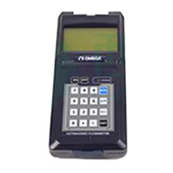
FDT-25 Handheld Ultrasonic Flowmeter §1.4 Parts Identification Converter: Front view Top vierw LCD DISPLAY stream transduer socket stream transduer socket LED Char g in g Indicator K e yp ad Pins for batter y rechar g e RS-232C communication interface... - Page 8 FDT-25 Handheld Ultrasonic Flowmeter Cab l e 5 m x2 Red Terminal Red Terminal Blue Terminal Blue Terminal Extended Cable 5m x2 (Opt ional Accessaries ) Red Terminal Red Terminal Blue Terminal B lue Terminal Converted Terminal and AC/DC Adapter...
-
Page 9: Typicalapplications
* STD-HS provided as standard with FDT-25. Other Transducers sold separately. § 1.5 T yp ical A pp lications The FDT-25 flow me ter can be virtually applied to a wide ran ge of measurements. The measured p i p e ran g es 2 0 6000 mm [0 . -
Page 10: Product Identification
FDT-25 Handheld Ultrasonic Flowmeter §1.7 Product Identification Each set of the FDT-25 Series flow meter has a unique product identification or ESN written into the software that can only be modified with a special tool by the manufacturer. In case of any hardware failure, please provide this number which is located on menu window number M61 when contacting the manufacture. -
Page 11: Starting Measurement
FDT-25 Handheld Ultrasonic Flowmeter 2. Starting Measurement §2.1 Built-in Battery The instrument can operate either from the built-in NiMH rechargeable battery, which will last over 10 hours of continuous operation when fully recharged, or from an external AC/power supply from the battery charger. -
Page 12: Keypad
FDT-25 Handheld Ultrasonic Flowmeter When new pipe parameters have been entered or when the power has been just switched on, the flow meter will enter an adjusting mode to make the signals magnified with proper amplification. By this step, the flow meter is going to find the best threshold of receiving signal. The user will see the progress by the number 1, 2, or 3, which are indicated on the right lower corner of the LCD display. -
Page 13: Menu Windows Arrangement
FDT-25 Handheld Ultrasonic Flowmeter (2) Pressing keys. Each time of the key pressing will proceed to the lower-numbered menu window. For example, if the current window is on M12, the display will go to the number M11 window after pressing the key. -
Page 14: Steps To Configure The Parameters
FDT-25 Handheld Ultrasonic Flowmeter Other menu windows such as M88 have no functions, or functions were cancelled because they are not applied to this version of the software. §2.6 Steps to Configure the Parameters The following parameters need to be configured for a proper measurement:... -
Page 15: Transducersmountingallocation
FDT-25 Handheld Ultrasonic Flowmeter The first-time users may need some time to get familiar with the operation. However, the user friendly interface of the instrument makes the operation quite easy and simple. Before long, the user will configure the instrument with very little key pressing, since the interface allows the user to go to the desired operation directly without any extra steps. -
Page 16: Transducersinstallation
FDT-25 Handheld Ultrasonic Flowmeter examples of optimum locations. Principles to selection of an optimum location (1) Install the transducers on a longer length of the straight pipe. The longer the better, and make sure that the pipe is completely full of liquid. -
Page 17: Z-Method Installation
FDT-25 Handheld Ultrasonic Flowmeter TOP VIEW OF PIPE Sensors Spacing Upstream transducer Downstream transducer Flow §2.8.3 Z-method Installation Z-method is commonly used when the pipe diameter is between 300 millimeters and 500 millimeters. TOP VIEW OF PIPE SensorsSpacing Upstream transducer... -
Page 18: N-Method Installation
FDT-25 Handheld Ultrasonic Flowmeter §2.8.5 N-method Installation Rarely used method. §2.9 Installation Checkup Through the checkup of the installation, one can: check the receiving signal strength, the signal quality Q value, the traveling time difference of the signals, the estimated liquid speed, the measured traveling time of the signals and the calculated traveling time ratio. -
Page 19: 4Timeratiobetweenthemeasuredtotal Transit Timeand The Calculatedtime
FDT-25 Handheld Ultrasonic Flowmeter The total transit time should remain stable or vary little. If the delta time fluctuates higher than 20%, it means there are certain kinds of problems with the transducer installation. §2.9.4 Time Ratio between the Measured Total Transit Time and the Calculated Time This ratio would be used to check the transducer installation. -
Page 20: How To
FDT-25 Handheld Ultrasonic Flowmeter 3. How To §3.1 How to judge if the instrument works properly When ‘R’ is displayed in the lowest right corner of LCD display, the instrument is working properly, generally speaking. If an ‘H’ flashes on that place, there could be poor signal received. Please refer to the chapters on diagnosis. -
Page 21: How To Restore The Flow Meter With Default Setups
FDT-25 Handheld Ultrasonic Flowmeter §3.8 How to restore the flow meter with default setups Use M37, when the ‘selection’ message is displayed. Press the dot key first and the message ‘Master Erase’ will display, then press the backspace key The master erase step will erase all the parameters entered by the user and setup the instrument with default values. -
Page 22: How To Use The Built-In Data Logger
FDT-25 Handheld Ultrasonic Flowmeter §3.14 How to use the built-in data logger The data logger has a space of 24K bytes of memory, which will hold about 2000 lines of data. Use M50 to turn on the logger and for the selection for the items that is going to be logged. -
Page 23: How To Produce An Alarm Signal
FDT-25 Handheld Ultrasonic Flowmeter The following setups should be taken/performed: (1) Select the unit Cubic Meter under window M32. (2) Select the Multiplier as ‘2. X0.1’ under window M33. (3)Select the output option ‘9. POS INT Pulse’ under window M77. (INT stands for totalized ) §3.17 How to produce an alarm signal... -
Page 24: How To Adjust The Lcd Contrast
FDT-25 Handheld Ultrasonic Flowmeter Press the ENT key under M61 for Modification. Use the dot key to skip over these digits that need no modification. §3.21 How to adjust the LCD contrast Use M70 to the LCD contrast. The adjusted result will be stored in the EEPROM so that the MASTER ERASE will make no effect on the contrast. -
Page 25: Menu Window Details
FDT-25 Handheld Ultrasonic Flowmeter 4. Menu Window Details Menu Function window Display three positive negative net totalizers, signal strength, signal quality and working status Display POS totalizer, flow rate, velocity, signal strength, signal quality and working status Display NEG totalizer, flow rate, velocity, signal strength, signal quality and working status... - Page 26 FDT-25 Handheld Ultrasonic Flowmeter Window for entering the fluid sonic velocity only for non-standard liquids Window for entering the viscosity of the non-standard liquids Window for selecting the proper transducers There are 14 different types of transducers for selection. If the user-type-transducers are used, 4 user type wedge parameters, which will be prompted by the software, should be entered following.
- Page 27 FDT-25 Handheld Ultrasonic Flowmeter by pressing the dot key followed by the backspace key. Take care or make note on the parameters before doing the restoration Press-a-key-to-run or to stop totalizer for easier calibration Operational interface language selection in Chinese and English. This selection makes it possible that more than 2 billions of people on the world can read the menu.
- Page 28 FDT-25 Handheld Ultrasonic Flowmeter Display Version information and Electronic Serial Number (ESN) that are unique for each series flow meter. The users can employ the ESN for instrumentation management RS-232 setup. Baud rate can be 75 to 115200 bps Not used...
- Page 29 FDT-25 Handheld Ultrasonic Flowmeter Not used Not used Not used Display signal strength, signal quality, time ratio on the upper right corner. Displays the Time Ratio between the Measured Total Transit Time and the Calculated time. If the pipe parameters are entered correctly and the transducers are properly installed, the ratio value should be in the range of 100±3%.
-
Page 30: Troubleshooting
FDT - 25 Handheld Ultrasonic Flowmeter Transducer Selection in Menu 23 Serial No. Transducer Not Used Not Used Not Used Not Used Not Used N ot Used N ot Used N ot Used Use for STD - HM and HT - HM N ot Used Not Used Not Used... -
Page 31: Error Code And Counter-Measures
FDT-25 Handheld Ultrasonic Flowmeter §5.2 Error Code and Counter -M easures The series ultrasonic flow meter will show Error Code in the lower right corner with a single letter like I, R etc. on menu windows M00, M01, M02, M03, M90 and M08. When any abnormal Error Code shows, counter-measures should be taken. -
Page 32: Other Problems And Solutions
FDT-25 Handheld Ultrasonic Flowmeter §5.3 Other Problems and Solutions (1) When the actual flow inside the pipe is not standstill, but the instrument displays 0.0000 for the flow rate, and ‘ R ’ displaying signal strength and the signal quality Q (value) has a satisfactory va l ue? Th e pr ob l e m s a r e lik e ly caused b y t h e use r w h o h as used t h e ‘S et Z e r o’... -
Page 33: Communication Protocol
FDT-25 Handheld Ultrasonic Flowmeter 6. Communication Protocol §6. 0 General The series ultrasonic flow meter integrates a standard RS-232C communication interface and a complete set of communication protocols that are compatible with that of the Fuji’s ultrasonic flow meter. §6.1 Interface Pin-out Definition... -
Page 34: Protocol Prefix Usage
FDT-25 Handheld Ultrasonic Flowmeter FOdddd(CR) ForcetheFOoutputwith afrequencyinddddHz ESN(CR) Return the ESN for the instrument Dddddddd(CR)(LF) RING(CR) Handshaking Request by a MODEM OK(CR) Response from a MODEM No action Command for GSM messaging Please contact factory for detail Command for GSM messaging... -
Page 35: Codes For The Keypad
FDT-25 Handheld Ultrasonic Flowmeter (2) Prefix W The prefix W should be used in the network environment. The usage format is W + digit string which stands for the IDN + basic command. The digit string should have a value between 0 and 65534 except 13(0DH), 10 (0AH), 42(2AH,*), 38(26H, &). - Page 36 Department will issue an Authorized Return (AR) number immediately upon phone or written request. Upon examination by OMEGA, if the unit is found to be defective, it will be repaired or replaced at no charge. OMEGA’s WARRANTY does not apply to defects resulting from any action of the purchaser, including but not limited to mishandling, improper interfacing, operation outside of design limits, improper repair, or unauthorized modification.
- Page 37 Where Do I Find Everything I Need for Process Measurement and Control? OMEGA…Of Course! Shop online at omega.com TEMPERATURE M U Thermocouple, RTD & Thermistor Probes, Connectors, Panels & Assemblies M U Wire: Thermocouple, RTD & Thermistor M U Calibrators & Ice Point References M U Recorders, Controllers &...
Need help?
Do you have a question about the FDT-25 and is the answer not in the manual?
Questions and answers