PS Engineering PMA8000BT System Installation And Operation Manual
Audio selector panel with marker beacon receiver
Hide thumbs
Also See for PMA8000BT:
- Installation and operation manual (40 pages) ,
- Pilot's manual and operation manual (21 pages)
Table of Contents
Advertisement
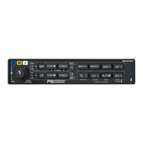
Audio Selector Panel with Marker Beacon Receiver
Patented under one or more of the following;
No. 4,941,187; 5,903,227; 6,160,496 and 6,493,450
In certified aircraft, warranty is not valid unless this product is installed by an
Any reproduction or retransmittal of this publication, or any portion thereof, without the expressed written permission of PS Eng i-
neering, Inc. is strictly prohibited. For further information contact the Publications Manager at PS Engineering, Inc., 9800 Ma rtel
Road, Lenoir City, TN 37772. Phone (865) 988-9800, email contact@ps-engineering.com.
9800 Martel Road
Lenoir City, TN 37772
www.ps-engineering.com
P
M
A
8
P
M
A
8
Document P/N 200-890-0702
Revision 1, Oct. 2010
High-fidelity Stereo Intercom
System Installation and Operation Manual
FAA- TSO C50c, C35d
EASA ETSO C50c, 2C35d
Authorized PS Engineering dealer.
PS Engineering, Inc. 2010 ©
Copyright Notice
0
0
0
B
T
0
0
0
B
T
Advertisement
Table of Contents

Related Manuals for PS Engineering PMA8000BT


Summary of Contents for PS Engineering PMA8000BT
- Page 1 Any reproduction or retransmittal of this publication, or any portion thereof, without the expressed written permission of PS Eng i- neering, Inc. is strictly prohibited. For further information contact the Publications Manager at PS Engineering, Inc., 9800 Ma rtel Road, Lenoir City, TN 37772. Phone (865) 988-9800, email contact@ps-engineering.com.
-
Page 2: Table Of Contents
IDDLE ARKER ENSE ............................. 2-9 DJUSTMENTS ................... 2-11 OMMUNICATIONS NTENNA NSTALLATION OTES 2.8.1 ......................2-7 UDIO CTIVE UTPUT PMA8000BT P ........................ 2-12 IN ASSIGNMENTS 2.10 ..........................2-13 IRING HECKOUT 2.11 ..........................2-13 NSTALLATION 2.12 ........................2-13 PERATIONAL HECKOUT 2.12.1 ....................2-13... - Page 3 IRWORTHINESS UDIO YSTEM Appendix F – RTCA DO160D Environmental Qualification Form......... F Date Change 7/1/ 2010 New Release of manual p/n -0702, for PMA8000BT 10/13/10 Clarified the Music 1 all headsets function §3.11.3 200-890-0702 Page ii Rev. 1, Oct. 2010...
-
Page 4: Section I - General Information
(Com 1, Com 2) and six receivers (Nav 1, Nav 2, ADF, DME, MKR and AUX). A full duplex TEL mode allows the PMA8000BT to act as an audio interface between aircraft headphone and microphones and specific aircraft approved (FAA/FCC) cellular telephone equipment, through the front mounted jack. -
Page 5: Approval Basis
The small volume knob controls the intercom level for the pilot and copilot, while the large knob controls the passenger intercom volume. Intercom squelch is automatic. A 3-light, 75 MHz Marker Beacon receiver is integrated in the PMA8000BT. This provides the necessary Marker Beacon lights and audio indications necessary for that portion of an Instrument Landing System (ILS) approach. - Page 6 PS Engineering PMA8000BT Audio Selector Panel and Intercom System Installation and Operator’s Manual Audio Selector Specifications Audio selector panel input impedance: 510 Input Isolation: -60 dB (min.) -60 dB (min.) Speaker Muting: Speaker Output (into 4 ) with no clipping 3 Watts (min.)
-
Page 7: Equipment Supplied
475-632-0012 #6-32 Clip Nut 475-630-0002 EQUIPMENT REQUIRED BUT NOT SUPPLIED Circuit Breaker: 1 ea; 5 amp PULL TYPE REQUIRED for PMA8000BT Speaker, 4 Headphone Jacks (Stereo, as Required) Microphone Jacks (as Required) Headphones, 150 (Stereo), up to 6 as required Microphones, up to 6 as required Marker Antenna (75 MHz, VSWR <1:1.5, and appropriate for the airspeed) -
Page 8: Section Ii - Installation
Section 1.6 (B). If any claim is to be made, save the shipping mat e- rial and contact the freight carrier. Do NOT return units damaged in shipping to PS Engineering. If the unit or accessories show any sign of external shipping damage, contact PS Engineering to arrange for a replacement. -
Page 9: Audio Panel Tray And Connector Assembly
There must be at least 13.8 VDC present at the conne c- tor, J2 pins 8 & 9, of the PMA8000BT for the power supply to work in its designed regulation. Otherwise, it cannot adequately attenuate power line noise. -
Page 10: Existing Gma340 Installation
2.4.3 Power The PMA8000BT is compatible with both 14 and 28 Volt DC systems. A five (5) Amp circuit breaker is required for all installations. Power and ground wires should be #22 connected to J2 Pins 8 and 9. Con- nect airframe ground to J2 Pin 10 and 11 only. - Page 11 King Radio KX170-series, require a resistive load to prevent damage if their speaker amplifier is not used. Connect the speaker output from the unit to the COM 2 Speaker load input on the PMA8000BT (J1 27 WRT 28). The speaker load is 16 , 3W.
-
Page 12: Phones
As shipped from PS Engineering, the PMA8000BT does NOT provide cellular telephone sidetone (the user’s voice fed back to the headset). Some cell phones do not provide sidetone. In PMA8000BT audio panels above serial number W04748, Telephone sidetone can be enabled by pressing the TEL and ADF... -
Page 13: Public Address Mode
2.4.11 Public Address Mode By pressing the Mute and SPR pushbuttons at the same time, the PMA8000BT will be placed into public address (PA) mode. In this mode, the pilot will be talking over the cockpit speaker when he presses his PTT switch. -
Page 14: Pa Mute (J2, Pin 12)
MIL-spec cable as shown. Connect the shields at the audio panel end only, and tie to the audio low inputs as shown. NOTE The intercom harness can be custom made by PS Engineering, Inc. Simply call the factory or www.ps- engineering.com to obtain a wire harness work sheet. -
Page 15: Entertainment Inputs
2.5.1 Entertainment Inputs The PMA8000BT has two INDEPENDENT music inputs, PLUS a front mounted jack that is connected to Entertainment 1. Entertainment input number 1 is J2 pins 23 (left channel) and 24 (right cha nnel), with respect to pin 25, and Entertainment number 2 is connected to 26 (left chann el), 27 (right channel), with respect to 28. -
Page 16: Playback Button Installation
The switch should be connected to pin 22 of J2 of the PMA8000BT, and ground. When installed, this button will act as in § 3.13. 2.6 Marker Beacon Installation 2.6.1... - Page 17 PS Engineering PMA8000BT Audio Selector Panel and Intercom System Installation and Operator’s Manual Shorter Screw Front of unit NOTE: If top cover is removed for ANY reason, you MUST replace the cover screws with the proper length, otherwise damage will result.
-
Page 18: Communications Antenna Installation Notes
It is probable that radio interference will occur in the split mode when the frequencies of the two ai r- craft radios are adjacent, and/or the antennas are physically close together. PS Engineering makes no expressed or implied warranties regarding the suitability of the PMA8000BT in Split Mode. 200-890-0702 Page 2-11 Rev. -
Page 19: Output
PS Engineering PMA8000BT Audio Selector Panel and Intercom System Installation and Operator’s Manual 2.9 PMA8000BT Pin assignments Function Function Mkr Ant Pilot Phones Low Mkr Ant Low Copilot Phones Low Telephone Audio in Copilot Phones (L) Telephone Low Copilot Phones (R) -
Page 20: Wiring Checkout
After wiring is complete, verify power is ONLY on pins 8 and 9 of the J2 and airframe ground on connec- tor pins 10 and 11. Failure to do so will cause serious internal damage and void PS Engineering's wa r- ranty. -
Page 21: Marker Checkout
2.12.4.1 Bluetooth Checkout (050-890-0702 only) Verify that the PMA8000BT will “pair” with a Bluetooth device, and interface with cellular phone and Music source. See section 3.12 for more information. 2.12.5 Internal Recorder Checkout With headset plugged into pilot’s side jacks, tune COM 1 to local frequency, such as FSS or ATC ground. -
Page 22: Section Iii Operation
Panel/Marker Beacon Receiver/Intercom Systems. Please read it carefully before using the equipment so that you can take full advantage of its capabilities. This section is divided into sections covering the basic operating areas of the PMA8000BT systems. They are Communications Transceiver Selection, Audio Selector, Intercom, Marker Beacon Receiver and spe- cial functions, including the Bluetooth®... -
Page 23: Audio Selector (4)
Com with the XMT buttons. 3.2.1.3 Monitor Mode The PMA8000BT is equipped with a Monitor function, which allows a secondary com radio audio to be muted by the primary radio (selected for transmit). See §3.11.2 for more information. 3.3 Audio Selector (4) Communication audio from the other radio, not selected for transmit, can be heard by pressing the assoc i- ated RCV button. -
Page 24: Cell Phone Sidetone
The pilot and copilot will also have transmit capability on the other selected transceiver. In ISO intercom mode, when the PMA8000BT is in the TEL mode, the pilot position is in the "Phone Booth." Only the pilot will hear the telephone, and only he will be heard. He will also have access to Com 1 or 2, and will transmit on that radio using the PTT. -
Page 25: Intercom Operation
Therefore, it may not recognize speech and clip syllables in a quiet cabin, such as in the hangar, or without the engine running. This is normal. For optimum microphone performance, PS Engineering recommends installation of a Microphone Muff Kit from Oregon Aero (1-800-888-6910). This will not only optimize VOX performance, but will improve the overall clarity of all your communications. -
Page 26: Intercom Modes (8)
Crew and may listen to entertainment as configured. 3.8 Music and Music Muting (6) The PMA8000BT has two independent music inputs at the rear connector, and a front panel jack. The PMA8000BT also has the ability to receive streaming music from a Bluetooth-enabled device. -
Page 27: Music In Pilot Iso Mode
(or Bluetooth connectivity (PMA8000BT only). When interfaced with an approved airborne telecommunications system, the PMA8000BT can serve as a audio control and distribution cen- ter. When TEL is active, the button will blink about twice as fast as the normal transmit rate. -
Page 28: Cellular Telephone Sidetone
Installation and Operator’s Manual In ISO intercom mode, when the PMA8000BT is in the TEL mode, the pilot position is in the "Phone Booth." Only the pilot will hear the telephone, and only he will be heard. He will also have access to Com 1 or 2, and will transmit on that radio using the PTT. -
Page 29: Smart Function Keys (Sfk)
You can’t do anything with these buttons to prevent the PMA8000BT from doing its main job. Looking at the front panel you’ll notice that the TEL, AUX, Mute and SPR buttons have “Function” as- signments. -
Page 30: Function "B" (Monitor Mode)
PS Engineering PMA8000BT Audio Selector Panel and Intercom System Installation and Operator’s Manual When Function A is toggled into “Alternate Intercom Function,” the passengers will NOT hear aircraft radios, even in the all mode. They will be able to converse with the crew. However, when the aircraft radio becomes active, the intercom audio from the passengers is muted, allowing the crew to focus on the radio. -
Page 31: Music 1 Volume
In general, we recommend adjusting the entertainment volume at the sources, and only using this as a master gain control. However, the Music 1 PMA8000BT input can be adjusted from the front panel, if desired, by pressing the combinations of keys listed. -
Page 32: Last Number Redial
-paired to allow the new device. The device eliminate will be selected at random by the Bluetooth module. Hint, if your old phone is not recognized by the PMA8000BT, you may simply need to re-pair. -
Page 33: Bluetooth Music Control
Installation and Operator’s Manual 3.12.4 Bluetooth music control The PMA8000BT can control some Bluetooth music devices. When the music is playing, press and hold the “Function” button (TEL), and push the desired music function button. Play/Pause (TEL and Nav 1) - Page 34 PS Engineering PMA8000BT Audio Selector Panel and Intercom System Installation and Operator’s Manual Figure 3-3 Playback Controls 200-890-0702 Page 3-13 Rev. 1, Oct. 2010...
-
Page 35: Section Iv - Warranty And Service
PS Engineering, Inc. The risk of loss or damage to the product is borne by the party making the shipment, unless the purchaser requests a specific method of shipment. In this case, the purchaser assumes the risk of loss. -
Page 36: Appendix A - External Ptt Hook Up
PS Engineering PMA8000BT Audio Selector Panel and Intercom System Installation and Operator’s Manual Appendix A – External PTT Hook Up Part of the installation includes the installation of PTT (Push To Talk) switches that allow the use of your aircraft radio for communications tran smissions. -
Page 37: Appendix B - Pma8000 Installation Drawings
PS Engineering PMA8000BT Audio Selector Panel and Intercom System Installation and Operator’s Manual Appendix B – PMA8000 Installation Drawings Viewed from Back Solder Lug (mount as convenient) Rear plate detail (not to scale) 6.31 in 1.28 in 1.28 in 0.96 in 0.36 in... -
Page 38: Appendix C - J1 Connector Interconnect
PS Engineering PMA8000BT Audio Selector Panel and Intercom System Installation and Operator’s Manual Appendix C – J1 Connector Interconnect PMA8000B Connector, J1 (Sub-D 44-pin, male on tray) Co m 1 A ud io Hi Notes: Communications Co m 1 L o 1. -
Page 39: Appendix D - J2 Connector Interconnect
PS Engineering PMA8000BT Audio Selector Panel and Intercom System Installation and Operator’s Manual Appendix D – J2 Connector Interconnect PMA8000B J2 CONNECTOR Pilot Phones (R) (Sub-D 44-pin male on tray) Pilot PhonesJack Pilot Phones (L) Pilot Phones Lo Copilot Phones (R) -
Page 40: Appendix E - Instructions For Faa Form 337 And Continuing Airworthiness
One method of airworthiness approval is through an FAA Form 337, Major Repair and Alteration (Airframe, Power- plant, Propeller, or Appliance) In the case of the PMA8000BT, you may use the following text as a guide. Installed audio selector and 6-place intercom, PS Engineering PMA8000BT, part number 050-890-(XXXX) in ( location ) at station . -
Page 41: Appendix F - Rtca Do160D Environmental Qualification Form
PS Engineering PMA8000BT Audio Selector Panel and Intercom System Installation and Operator’s Manual Appendix F – RTCA DO160D Environmental Qualification Form Audio Selector Panel/Intercom/Marker Beacon Receiver Part Number: 050-890-( ) FAA TSO Number: C50c, C35d Manufacturer: PS Engineering Incorporated 9800 Martel Road...
Need help?
Do you have a question about the PMA8000BT and is the answer not in the manual?
Questions and answers