
Related Manuals for Martin Audio MLA MINI


Summary of Contents for Martin Audio MLA MINI
- Page 1 MARTIN AUDIO MLA MINI MLA MINI ADVANCED USER GUIDE (INCLUDING DISPLAY 2.2 AND VU-NET 2.0 FOR MLA MINI)
-
Page 2: Table Of Contents
MLA MINI ADVANCED USER GUIDE CONTENTS SAFETY INFORMATION ..................4 Important Safety Instructions ..............4 Safety Rules ....................6 MLA MINI HARDWARE ..................7 DISPLAY 2.2.0 FOR MLA MINI .................81 VU-NET 2.0.0 FOR MLA MINI ................165 MLA Mini Advanced User Guide V1.0... - Page 3 MLA MINI ADVANCED USER GUIDE MLA Mini Advanced User Guide V1.0...
-
Page 4: Safety Information
CAUTION To reduce the risk of electric shock do not remove any covers. There are no user serviceable parts inside the units. Refer servicing to qualified service personnel only. Call Martin Audio Ltd on +44 (0) 1494 535312 or e-mail info@martin-audio.com... - Page 5 APPROVALS Safety: IEC60065:2002 + A1:2006 Environmental: IP25 when fitted with MSX cowl assembly (Martin Audio Part No. ASF15027) and used with mains connectors/cords rated to at least IP25. IP2X when NOT fitted with cowl assembly or not used with mains connector/cords rated to at least IP25.
-
Page 6: Safety Rules
• When not fitted with the optional MSX rain cowl (Martin Audio Pt No ASF15027) or not used with mains connector/cords rated to at least IP25, the MSX must not be exposed to dripping, or splashing and no objects filled with liquids, such as vases should be placed on the apparatus. -
Page 7: Mla Mini Hardware
MLA MINI ADVANCED USER GUIDE MLA MINI HARDWARE MLA Mini Advanced User Guide V1.0... - Page 8 Cabling, connecting up ................28 ADVANCED SYSTEM CONFIGURATION .............30 Display 2.2 – Introduction ..............30 Vu-Net - Introduction................31 Using MLA Mini with digital audio sources .........32 Optional system components .............32 MLA Master Rack ................34 MLA Slave Rack ..................34 MLA Front of House (FOH) Rack ............35 Silex USB to Ethernet Device Server ..........35...
- Page 9 ADVANCED USER GUIDE RIGGING ......................54 Rigging Option 1: Pole Mount with Universal or Fixed Tilt Bracket ....55 Rigging Option 2: Ground Stacked MLA Mini array on MSX sub(s) ....61 Rigging Option 3: Ground Stacked MLA Mini array with separate MSX sub(s) ................66 Rigging Option 4: Flown Mini array, with MSX sub(s) on floor .......68...
-
Page 10: Introduction
The rigging design of MLA Mini systems has been based on the existing popular and efficient Martin Audio line array systems, but with some innovative improvements. This allows phenomenally quick system rigging and de-rigging, particularly aided by the absence of separate amplifier racks. -
Page 11: Unpacking The Mla Mini Components
MLA MINI ADVANCED USER GUIDE MLA Mini systems are designed for use indoors or outdoors in virtually any weather conditions. Basic unit rating is IP2X, but the MSX may be protected by a waterproof flexible cowl which gives it an IP25 rating. -
Page 12: Overview
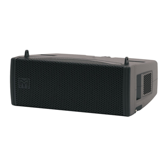
ADVANCED USER GUIDE OVERVIEW Like the MLA and MLA Compact systems from which it is derived, the MLA Mini is a precision multicellular loudspeaker array designed to accurately deliver a required SPL (acoustic loudness) within a defined area. Smaller and lighter than the MLA and MLA Compact systems, the MLA Mini will reproduce high quality sound in smaller venues, as either a fixed or portable installation. -
Page 13: Msx - Rear Panel
MSX cabinet. 1. INPUT – a 3-pin female XLR audio input connector. The MLA Mini system can be fed with either balanced analogue audio or AES3 digital audio. The same connector is used for both formats, and the analogue/digital selection is made via VU-NET control software. -
Page 14: Neutrik® Powercon True1 Connector Assembly Instructions
9.5 - 12.0 mm Place bushing and chuck over the cable. 20 mm 20 mm [0.787”] [0.787”] 8 mm 8 mm [0.32"] [0.32"] Prepare cable as shown. PE 23 mm PE 23 mm [0.9”] [0.9”] MLA Mini Advanced User Guide V1.0... - Page 15 Wrench size tighten it with the tool as shown. 10 mm (Tool available: Art. No. HTAC) Disassembly (open twist lock): 1. Press with screw driver to unlock 2. Turn bushing while still pressing locking. MLA Mini Advanced User Guide V1.0...
-
Page 16: Mla Mini Connection
ADVANCED USER GUIDE MLA MINI CONNECTION The MLA Mini system only has one other connection. This is a Neutrik® NL4 on the Mini cabinets themselves. Connect the cables referred to in Item [3] above here, taking care to observe the colour coding of the connectors. -
Page 17: Mla Mini System Mechanical Components
Flying Frame This steel assembly is required when an MLA Mini system is to be flown using one or two chain hoists; it attaches either to the Mini array or to the topmost MSX, depending whether one or more MSXs are being flown as part of the array. - Page 18 This is used in a flown arrangement to attach a Mini array to the underside of an MSX sub. Variable Height Pole Mount (Martin Audio Part No. ASF20071) This is used to elevate an array of 4 Minis above the MSX as a single assembly. The height of the array can be set to that required (either determined by the Preset in use or according to the Display 2.2 specifications) by turning the handle, and then locked in position with the integral...
- Page 19 MLA MINI ADVANCED USER GUIDE Fixed Tilt Bracket (Martin Audio Part No. ASF20053) This is a simpler alternative to the Universal Tilt Bracket, for use with the Vertical Height Pole Mount. It provides a single tilt angle (14.5°), which is correct for use with two of the Presets most likely to be used with pole mount configurations.
- Page 20 Mini array and an MSX sub when the system is configured for ground stacking. They will also be needed when the Mini array is to be ground stacked alone. Two versions are available, long (Martin Audio Part No. ASF20056) and short (ASF20057); the two sizes allow different ranges of angles to be set.
- Page 21 (except the flying pins – but see below) should be removed before stowing the Minis in the flightcase for shipment. Four MLA Mini cabinets may be ordered complete with the flightcase as Martin Audio Part No. ASF17024.
- Page 22 MLA MINI ADVANCED USER GUIDE Wheelboard with castors (Martin Audio Part No. ASF90011) This is a wheeled base board which is fitted to the front of the MSX sub (for speaker protection) to allow easy attachment of the Ground Stack Baseplate, and also for convenient transportation.
-
Page 23: System Configuration Using On-Board Presets
ADVANCED USER GUIDE SYSTEM CONFIGURATION USING ON-BOARD PRESETS An MLA Mini system can be rigged in a wide variety of ways, in both ground-stacked and flown configurations. The system size and rigging option to be used will generally be dictated by the venue’s size and physical restrictions. -
Page 24: Choosing A Preset
Mini. The selected preset optimises the MLA Mini system for the dimensions and heights shown in the diagrams, but good performance will still be obtained if, for example, the room is a different size or if it necessary to use a different mounting height. - Page 25 audience. Note the array tilt and inter-cabinet angles differ again. MLA Mini Advanced User Guide V1.0...
- Page 26 MLA Mini Advanced User Guide V1.0...
- Page 27 2 - 17 m Standing Ground stack On stage 2 – 12 m Standing Flown array Sub on floor, array flown 2 – 12 m Standing Fully flown Fully flown 2 – 12 m Standing MLA Mini Advanced User Guide V1.0...
-
Page 28: Cabling, Connecting Up
MSX sub. Do not connect the other end of the cable to a live AC supply at this stage. 2. Connect the amplifier outputs to the MLA Mini cabinets using the pre-made cable assembly supplied (if length permits - configuration-dependent. Some configurations will require longer cables). - Page 29 Apply power to the MSX electronics rack; check that the POWER LED is illuminated. 0.5° If required, select the preset to be used using the PRESET SELECT button. 4° 10° Gradually raise the output level of the mixing console. 2m MLA Mini Advanced User Guide V1.0...
-
Page 30: Advanced System Configuration
Presets to be used. Display 2.2 is used in conjunction with Vu-Net and an MLA Mini system to calculate i) the inter- cabinet angles to be used when rigging the system, and ii) the DSP parameters to optimise the loudspeaker management system. -
Page 31: Vu-Net - Introduction
Mini systems will continue to pass audio with their last known configuration even without a operational U-Net network. A full description of the operation of Vu-Net can be found in the “VU-NET 2.0.0 for MLA Mini” on page 165 MLA Mini Advanced User Guide V1.0... -
Page 32: Using Mla Mini With Digital Audio Sources
Presets all configure the input connector for analogue audio; however, if a Preset configuring the MLA Mini for use with AES3 audio is saved in one of the User memories, the XLR input will be switched from analogue to digital when that Preset is selected by whatever means. This implies... - Page 33 The remaining rear panel connectors are concerned with Merlin’s audio and DSP functions, which are not essential for use with an MLA Mini system. NOTE: Use of Merlin as a U-Net hub is covered at page 36 in this Advanced User Guide.
-
Page 34: Mla Master Rack
In this situation, it is useful to have a second U-Net/Ethernet switch (plus the possibility of additional derived fill feeds) on stage. The MLA Slave Rack is a 4U flightcase with the same components as the MLA Master Rack, except that the Wi-Fi router is omitted. MLA Mini Advanced User Guide V1.0... -
Page 35: Mla Front Of House (Foh) Rack
Silex USB to Ethernet Device Server With smaller MLA Mini systems, it may not be cost-effective or appropriate to install one or more Merlin units or Racks to implement U-Net control of the system, and it also may not be practical to connect directly to the MSX unit via its USB port due to the 5 m maximum cable length that USB operation imposes. -
Page 36: Using Merlin
Martin Audio or third-party speaker systems. This functionality is not required when Merlin is used with MLA Mini systems, as all necessary DSP is contained within the MSX power plant. This MLA Mini Advanced User Guide ignores the audio I/O and DSP aspects of Merlin;... -
Page 37: U-Net Topologies
Bearing in mind the points made above (“U-Net topologies”), the diagrams below show the possible data interconnections that can be used with MLA Mini systems of two different sizes. Option 1 to 3 are for a single 4 x Mini + MSX array; Options 4 and 5 are for a pair of arrays of the same configuration, and Options 6 to 10 are for systems double this size –... - Page 38 PC to MSX via Silex Ethernet Convertor & USB Ethernet (80m Maximum) ETHERNET USB (5m Maximum) MINI SILEX USB to Ethernet This uses a Silex USB-to-Ethernet converter to extend the maximum cable run to 85 m. MLA Mini Advanced User Guide V1.0...
- Page 39 PORT 1 PORT 2 When more than a single MLA Mini array is in use, a USB connection may be made to one MSX’s USB port as in Option 1, and a single U-Net interconnection made between the two subs. No operational redundancy is provided by this arrangement.
- Page 40 Link Link U-Net U-Net Port 2 U-Net (113m Maximum inc Cat5) U-Net (113m Maximum inc CAT5) Port 2 U-Net U-Net Port 1 Port 1 RJ45 to U-Net RJ45 to U-Net Barrel Barrel PCX00043 PCX00043 MLA Mini Advanced User Guide V1.0...
- Page 41 MLA MINI ADVANCED USER GUIDE This arrangement shows the same MLA Mini array configuration as Option 6, but demonstrates how a Merlin processor can be used as a U-Net hub. The connection between the PC and the Merlin is now via Ethernet. Each of the Merlin’s two U-Net ports feed the arrays on one side of the stage, which are themselves daisy-chained together.
- Page 42 Connection between the MLA Master Rack and the Front of House Rack is via a single twisted pair cable, which will typically be a spare channel of the audio multicore cable. This arrangement overcomes the problem of degraded wireless access when the venue is full. MLA Mini Advanced User Guide V1.0...
-
Page 43: Cabling, Connecting Up
Thus all MLA Mini arrays must consist of 4, 8, 12 or 16 cabinets; no other quantities are possible. These array sizes will require 1, 2, 3 or 4 MSX subs respectively. - Page 44 MLA MINI ADVANCED USER GUIDE Option 2 8 Mini Ground Stack systems GREEN ORANGE ASF12026 Speaker Loom GREEN ORANGE MLA Mini Advanced User Guide V1.0...
- Page 45 MLA MINI ADVANCED USER GUIDE Option 3 MLA Mini Flown Below MSX ORANGE GREEN ASF12026 Speaker Loom MLA Mini Advanced User Guide V1.0...
- Page 46 MLA MINI ADVANCED USER GUIDE Option 4 8 x MLA Mini Flown Below MSX ORANGE GREEN ASF12026 Speaker Loom ORANGE GREEN MLA Mini Advanced User Guide V1.0...
- Page 47 MLA MINI ADVANCED USER GUIDE Option 5 Flown MLA Mini, Ground Stack MSX ASF12026 Speaker Loom Neutrik NL8MM Connector Barrel Standard Speaker Cable ORANGE GREEN MLA Mini Advanced User Guide V1.0...
- Page 48 MLA MINI ADVANCED USER GUIDE Option 6 8 x Flown MLA Mini, Ground Stack MSX ASF12026 Speaker Loom Neutrik NL8MM Connector Barrel ORANGE GREEN Standard Speaker Cable ORANGE GREEN MLA Mini Advanced User Guide V1.0...
- Page 49 MLA MINI ADVANCED USER GUIDE Option 7 Flown MLA Mini, Ground Stack MSX ASF12031 Speaker Cable Breakout 4 x NL4 ASF12029 Tourmate Cable (15M) ASF12002 Tourmate Cable (30m) Any standard Socapex Pattern Cable ORANGE ASF12030 Speaker Cable Breakout 2 x NL8 GREEN MLA Mini Advanced User Guide V1.0...
- Page 50 MLA MINI ADVANCED USER GUIDE Option 8 8 x Flown MLA Mini, Ground Stack MSX ASF12031 Speaker Cable Breakout 4 x NL4 2 x ASF12029 Tourmate Cable (15M) 2 x ASF12002 Tourmate Cable (30m) 2 x Any standard Socapex Pattern Cable...
-
Page 51: Standard Cable Looms
Martin Audio Part No. ASF12026 ASF12026 is a speaker cable loom designed to connect one MSX to four MLA Mini cabinets. It has two NL8 connectors at one end (the MSX) and four NL4 connectors at the other for the MLA Minis. - Page 52 Martin Audio Part Nos. ASF12030 and ASF12031 In situations where the MLA Mini cabinets are flown but the MSX sub is ground stacked, a longer cable loom must be run from the ground (or stage level) up to the array. There are two ways to achieve this.
- Page 53 We recommend cable of a minimum gauge of 2.5 mm² (13 AWG) is used for lengths up to 35 m, and 4 mm² (11 AWG) for lengths in excess of 35 m. However, the MLA Mini is a relatively low power system: 300W LF, 90W HF per cabinet, thus only a minimal effect on performance should be observed if a smaller gauge is used –...
-
Page 54: Rigging
This section of the Advanced User Guide covers the mechanical aspects of assembling the various components of the MLA Mini system into the various possible rigging configurations. The components required for each are summarised in the table below. Note that the component count applies to a single system;... -
Page 55: Rigging Option 1: Pole Mount With Universal Or Fixed Tilt Bracket
(the rear location is only needed for larger configurations). With the MSX on its wheelboard and the front edge of the Baseplate on the floor, the dropdown brackets should align with the correct holes. Secure all four dropdown brackets with Flying Pins. MLA Mini Advanced User Guide V1.0... - Page 56 Display 2.2, the Universal Tilt Bracket must be used. Attach the bracket to be used to the top of the telescopic pole and secure by tightening the boss onto the pole using the knob. MLA Mini Advanced User Guide V1.0...
- Page 57 MLA MINI ADVANCED USER GUIDE Step 4a (with Universal Tilt Bracket): Lift the first MLA Mini cabinet onto the Universal Tilt Bracket. The lugs on the ends of the main cross-arm should mate with the slots in the front corners of the cabinet. Secure these points with flying pins. Attach the rear lug of the bracket to the Ground Stack hole (marked with a ) in the cabinet’s rear mounting plate.
- Page 58 MLA MINI ADVANCED USER GUIDE Step 4b (with Fixed Tilt Bracket): Lift the first MLA Mini cabinet onto the bracket. The lugs on the ends of the main cross-arm should mate with the slots in the front corners of the cabinet.
- Page 59 ADVANCED USER GUIDE Step 6: Repeat Step 5 twice to add the two remaining MLA Mini cabinets, while referring to the angles which have been defined by Display 2.2, or if using Presets 1, 2 or 3, to the tables below.
- Page 60 Cabinets 3 & 4 0.5° Summary of angles for Preset 3: Preset 3 Bracket tilt angle 11° Cabinets 1 & 2 10° Inter-cabinet Cabinets 2 & 3 0.5° angles Cabinets 3 & 4 0.5° MLA Mini Advanced User Guide V1.0...
-
Page 61: Rigging Option 2: Ground Stacked Mla Mini Array On Msx Sub(S)
The Ground Stack Baseplate is used in combination with the Flying Frame to build floor-standing MLA Mini configurations. Two options are permissible: • a single MSX sub may be fitted to the Baseplate, with an array of four MLA Mini cabinets attached to the top using the Flying Frame, or, •... - Page 62 Display 2.2. With the MSX on its wheelboard and the front edge of the Baseplate on the floor, the dropdowns should align with the correct holes. Secure all four dropdown brackets with Flying Pins. MLA Mini Advanced User Guide V1.0...
- Page 63 Flying Frame at the correct mark and secure with a Flying Pin. For the 4+1 configuration used by Preset 4 the angle between is 20°, so the Long Ground Stack Bar must be used in this case. MLA Mini Advanced User Guide V1.0...
- Page 64 Step 5: Next, raise the two front lugs of the Flying Frame to their upright position, and secure. These will mate with the front slots of the first Mini. Fit the first MLA Mini cabinet onto the Flying Frame, locking the two front slots into place with Flying Pins. Note that the front of the Flying Frame should be flush with the lower front edge of the cabinet.
- Page 65 Step 8: Repeat Step 7 either twice (for a 4+1 rig) or six times (for an 8+2 rig) to add the remaining MLA Mini cabinets, while referring to the results obtained from Display Mini 2.1 to set the correct angles. Alternatively, refer to the table below if Preset 4 is to be used.
-
Page 66: Rigging Option 3: Ground Stacked Mla Mini Array With Separate Msx Sub(S)
RIGGING OPTION 3: GROUND STACKED MLA MINI ARRAY WITH SEPARATE MSX SUB(S) An alternative method of rigging four- and eight-MLA Mini arrays is to mount them directly onto the Ground Stack Baseplate using the Flying Frame. In this situation, the MSX subs – either one or two per side depending on array size –... - Page 67 Step 3: Next, raise the two front lugs of the Flying Frame to their upright position, and secure. These will mate with the front slots of the first Mini. Fit the first MLA Mini cabinet onto the Flying Frame, locking the two front slots into place with Flying Pins. Note that the front of the Flying Frame should be flush with the lower front edge of the cabinet.
-
Page 68: Rigging Option 4: Flown Mini Array, With Msx Sub(S) On Floor
The weight of the MLA Mini cabinet is such that even a 16-cabinet array with four MSX subs should not exceed the safe working limit of a normal hoist. Weights of the arrays and the Flying Frame are summarised below. - Page 69 MLA MINI ADVANCED USER GUIDE Step 1: Start with the first four MLA Mini cabinets face down on their flightcase base. The cabinets should be locked together with Flying Pins at the front and rear, with the rear pins in the “0.5”...
- Page 70 Step 5: (This step may be omitted if the flown array is now complete.) Wheel the next set of four MLA Mini cabinets on their flightcase base into position below the suspended array. Adjust the hoist and the flightcase base so that the lowest cabinet in the array is in a convenient position to be mated with the top cabinet in the next set of four cabinets.
- Page 71 MLA MINI ADVANCED USER GUIDE Step 6: Continue raising the array on the hoist until the lower edge of the bottom MLA Mini cabinet is at the height defined by Display Mini 2.1. If the Flying Frame is fitted with a clinometer, the forward tilt angle can be checked with the clinometer display, and adjusted by differential adjustment of the two hoists.
-
Page 72: Rigging Option 4A: Flown Four-Mini Array Using Universal Tilt Bracket, Msx Sub On Floor
Trigger Clamp to the bracket’s fixing hole with an M12 nut and bolt. Start with the first four MLA Mini cabinets face down on their flightcase base. The cabinets should be locked together with Flying Pins at the front and rear, with the rear pins in the ’0.5’... - Page 73 Step 5: The correct height for the array will be defined by Display Mini 2.1. If using Preset 5, this height is 2.38 m (measured from the stage or other floor to the bottom of the lowest cabinet). MLA Mini Advanced User Guide V1.0...
-
Page 74: Rigging Option 5: Fully-Flown Arrays
MLA MINI ADVANCED USER GUIDE RIGGING OPTION 5: FULLY-FLOWN ARRAYS MSX subs may be assembled with MLA Mini cabinets to form a full-range flying array. Three configurations are possible: • four MLA Mini cabinets plus one MSX sub • eight MLA cabinets plus two MSX subs •... - Page 75 Extend the four dropdown brackets and engage them into the four slots in the top of the sub. The front edge of the Flying Frame should be aligned with the front face of the MSX. Secure the dropdown brackets in place with four Flying Pins. MLA Mini Advanced User Guide V1.0...
- Page 76 Secure the dropdown brackets with Flying Pins. Raise the hoists further to clear the wheelboard. If you are rigging a 12+3 array, perform Step 3 once again, to attach the third MSX sub. MLA Mini Advanced User Guide V1.0...
- Page 77 MLA MINI ADVANCED USER GUIDE Step 4: Assemble the first array of four MLA Mini cabinets face down on their flightcase base. Attach the Transition Frame to the upper MLA Mini cabinet with Flying Pins. The frame connects at three points: two are the cabinet’s front location points, which engage with slots in the frame;...
- Page 78 Step 8: (This step may be omitted if the flown array is now complete.) Wheel the next set of four MLA Mini cabinets on their flightcase base into position below the suspended array. Adjust the hoist and the flightcase base so that the lowest cabinet in the array is in a convenient position to be mated with the top cabinet in the next set of four cabinets.
- Page 79 ADVANCED USER GUIDE Step 9: Continue raising the array on the hoist until the lower edge of the bottom MLA Mini cabinet is at the height defined by Display Mini 2.1. If the Flying Frame tilt angle is fitted with a clinometer, the tilt can be checked with the clinometer display.
-
Page 80: Contact Info
Martin Audio Ltd. cannot be held responsible for defects caused by unauthorised modifications, improper use, negligence, exposure to inclement weather conditions, act of God or accident, or any use of this product that is not in accordance with the instructions provided by Martin Audio. Martin Audio is not liable for consequential damages. -
Page 81: Display 2.2.0 For Mla Mini
MLA MINI DISPLAY 2.2 DISPLAY 2.2.0 FOR MLA MINI MLA Mini Display 2.2 V1.0... - Page 82 MLA MINI DISPLAY 2.2 CONTENTS DISPLAY 2.2.0 FOR MLA MINI .................81 INTRODUCTION ....................84 Installation ....................84 System requirements ................84 Latest Version ..................85 Numerical Optimisation ................85 Index Plots ....................87 APPLICATION MENU ..................98 Getting Started ..................100 Add an Array ..................101 SLICE TAB ....................106 Slice Setup ...................106...
- Page 83 Goals ....................144 Optimise EQ’s ..................146 View the SPL ..................148 INDIVIDUAL GRAPH WINDOWS ..............151 ADDING ADDITIONAL ARRAYS ...............155 Deleting an array ...................155 EXPORTING THE OPTIMISATION ..............156 Exporting D2P Files ................156 Exporting to DXF ..................157 Printable Reports ...................161 MLA Mini Display 2.2 V1.0...
-
Page 84: Introduction
DSP optimisation parameters which can then be quickly and easily uploaded to the hardware over the U-Net system network or in the case of MLA Mini directly using a USB connection. It also shows accurate analysis of the system response in the venue. -
Page 85: Latest Version
Users have reported that Display2.2 works perfectly well on an Apple Mac using Bootcamp or under a virtual platform such as VM Ware Fusion or Parallels, (these options still require a copy of Windows Vista, 7, 8 or 10 to be installed) however this is not supported by Martin Audio. LATEST VERSION From version 2.2 onwards there is greater interaction with Vu-Net v2.0 so it is important to... - Page 86 This is a very basic explanation, in fact it is Martin Audio’s development of the revolutionary but phenomenally complex digital algorithm that the application uses to refine the optimisation which give the best possible results in a reasonable time frame.
-
Page 87: Index Plots
INDEX PLOTS The other concept which Martin Audio developed as part of the MLA system is the index plot. We needed a method to display the results of the system optimisation that was clear and easy to interpret. - Page 88 Just above this is the back wall and then up to the number 200 is the venue ceiling and the last section of the graph is the back of the venue behind the array. MLA Mini Display 2.2 V1.0...
- Page 89 MLA MINI DISPLAY 2.2 This shows the bottom portion of the index plot corresponds to the stage and “pit” leading up to the start of the audience coverage. MLA Mini Display 2.2 V1.0...
- Page 90 MLA MINI DISPLAY 2.2 This section of the index plot corresponds to the first portion of the audience plane up to the reference point. MLA Mini Display 2.2 V1.0...
- Page 91 This is the section from the reference point to the back of the audience area. The strong band of red indicated the front of the balcony which is getting a great deal of direct sound prior to optimising the system. MLA Mini Display 2.2 V1.0...
- Page 92 MLA MINI DISPLAY 2.2 This is the narrow section corresponding to the rear wall. MLA Mini Display 2.2 V1.0...
- Page 93 MLA MINI DISPLAY 2.2 This is the response on the ceiling. MLA Mini Display 2.2 V1.0...
- Page 94 Just to re-emphasis, these plots are prior to any system optimisation; they show the response of an array flown with all angles at 0.5°! MLA Mini Display 2.2 V1.0...
- Page 95 On the index plot we see a block of orange which gradually fades through yellow, green and indigo to blue at the highest frequencies. MLA Mini Display 2.2 V1.0...
- Page 96 16 MLA plus 1 MLD optimised to obtain a front to back differential of 0 dB - exactly the same SPL everywhere. The audience target has been given maximum priority ignoring non-audience and hard avoid areas: MLA Mini Display 2.2 V1.0...
- Page 97 MLA Mini Display 2.2 V1.0...
-
Page 98: Application Menu
Next you can save the current project and finally you can start a new project. Note that until you have actually started on a project and saved it, the ‘create new project’ option will have no effect. MLA Mini Display 2.2 V1.0... - Page 99 This is the final stage of the design process and we will look at this process later in this guide. The Help menu brings up a set of options for the project which can be selected to suit the design you are working on. MLA Mini Display 2.2 V1.0...
-
Page 100: Getting Started
Auto Use Splay will instantly apply the optimised angles to the array model. With this disabled you can review the array shape before applying the angles to the project. In most cases this can be left enabled. MLA Mini Display 2.2 V1.0... -
Page 101: Add An Array
‘Add’ tab and click on the array icon. The following window will appear: In the first drop-down you must select the type of array, ‘MLAM’ meaning MLA Mini. “None” has very limited use (perhaps for silent discos?). MLA Mini Display 2.2 V1.0... - Page 102 The options for MLA Mini are flown with sub, ground stacked, ground stacked on sub and pole mount: Next you need to select the total number of cabs. The...
- Page 103 MLA MINI DISPLAY 2.2 When flying with subs the maximum is 12 MLA Mini: For ground stacked systems either on the floor or on top of the MSX, the maximum is 8 cabinets: MLA Mini Display 2.2 V1.0...
- Page 104 You will notice on the right hand side the ‘Rename’ box. This gives you the opportunity to rename your array. Simply click in the box, type in the new name and press return. The Rename box will briefly turn green and the array name will change on the tab. MLA Mini Display 2.2 V1.0...
- Page 105 This feature forces you to complete the project design process in the correct, logical order. Once you have completed each section you are then able to go back and access any of the completed parts of the design. MLA Mini Display 2.2 V1.0...
-
Page 106: Slice Tab
Choose the one which has the shell you wish to use. Note that only the shell data is imported, the array and other optimisation parameters are ignored: Click import and the Slice Editor window appears with the shell already drawn (see following page). MLA Mini Display 2.2 V1.0... - Page 107 However, if we assume that we have to draw a shell from scratch, ignore the ‘Import Shell’ section, enter very approximate maximum dimensions for the length and height of the venue and click OK, the 2D Slice window will appear: MLA Mini Display 2.2 V1.0...
-
Page 108: Draw A Shell
You will now see that a number of additional buttons are active and these can be used to perfect the venue drawing. MLA Mini Display 2.2 V1.0... -
Page 109: Edit The Shell
Tab again and the x figure for node 2 is highlighted and so on. You will get very quick at tabbing through all the coordinates entering the correct values to give you a perfectly accurate 2D slice drawing. This obviously is a far quicker method of working. MLA Mini Display 2.2 V1.0... -
Page 110: Using Survey
Disto D510 which is supplied as part of full MLA and MLA Compact systems and is available from Martin Audio as an optional accessory. The Distos have been in widespread use for accurately measuring venues for line array software so most technicians are familiar with their operation and accuracy. -
Page 111: Position The Array
If for example the stage is 5 metres deep and the x figure is 3m MLA Mini Display 2.2 V1.0... -
Page 112: Add The Audience Region
6m the array would be on the floor. For MLA Mini systems a grey box will appear above the array if flown with sub has been selected: Or below the array if stack with sub has been selected: It shows the space occupied by the MSX subs. -
Page 113: Editing The Audience Region
Assuming you have drawn an accurate representation of the venue (and remember that the more accurate the D2 project, the better the audible results), you have now finished entering the venue slice and can click on ‘Done’ to close the window. MLA Mini Display 2.2 V1.0... -
Page 114: Coverage Tab
Whilst we have a tremendous amount of processing power available, we MLA Mini Display 2.2 V1.0... -
Page 115: Changing Plane Properties
If you get several wrong you can click on the Reset which returns all planes to the default that you started with. MLA Mini Display 2.2 V1.0... -
Page 116: Audience Offsets
In these instances you need to un-check the Uniform Offset button and define the offset for each plane individually. When you uncheck the box the controls change and look like this: MLA Mini Display 2.2 V1.0... - Page 117 When you are using Custom offsets, you can define a different custom height for each plane if required, you are not restricted to a single global figure. Our example now has a standing audience downstairs and a seated upstairs: MLA Mini Display 2.2 V1.0...
-
Page 118: Air Absorption Compensation
A 6.00 am load-in is going to give very, very different readings compared to a packed, 8.00pm show with all lighting, smoke machines and pyrotechnics going full tilt! MLA Mini Display 2.2 V1.0... -
Page 119: Target Delta Selection
3dB drop in level for every doubling of distance away from their arrays, with MLA Mini you can simply specify the precise loudness contour you desire across the venue. If you want the back row to be as loud as the front then you simply type 0 in both the start and stop delta positions and the system will give you exactly that. - Page 120 550 feet from the array. It would however be very difficult to get such an astonishing result from say an eight box MLA Mini array. The height of the array also has a significant effect, a ground stacked system will not be able to achieve low figures for start and stop as a flown array.
- Page 121 +10dB, for MLA Compact or other system optimised at 105dB the input gain will be set to +5dB and for MLA Mini or other system optimised at 100dB or less the gain will remain at 0dB Once you have determined your Start and Stop Deltas you can click on Done to close the Coverage window and you can move on to the Splay tab.
-
Page 122: Splay Angle Tab
Having completed the Coverage you will be able to open the Splay tab and the default window will appear as follows: There are a number of sections to the window, these are: Splay angles, Current Acoustic Output, Optimised Acoustic Output, Calculation, Array Diagram, Optimisation and Optimisation Progress. MLA Mini Display 2.2 V1.0... -
Page 123: Splay Angles
We will discuss this option later. At the bottom of the list is a rest button which will return all angles to 0.5°. CURRENT ACOUSTIC OUTPUT This shows an Index Plot of the system prior to the optimisation process. MLA Mini Display 2.2 V1.0... -
Page 124: Coverage / Current Best Optimised Output
3.25° beyond the upper line and 3.25° lower than the bottom line for MLA or 10° lower if MLD are used at the bottom of the array. For MLA Compact and MLA Mini it will be 5° higher and 5°... -
Page 125: Calculation
6 for ground stacked MLA or MLA Compact, 8 for ground stacked MLA Mini 12 for MLA Mini flown with MSX. The height to the top of the array and distance from the origin is also shown and can be edited to match the physical deployment of the system, very useful if for example it wasn’t possible to... -
Page 126: Array Diagram
This is because the array starting point is with an almost straight array with all angles at 0.5°, once the optimisation is complete some of the angles will inevitably be higher thus reducing the overall height of the array and raising the lower trim height. MLA Mini Display 2.2 V1.0... -
Page 127: Optimisation
Run the optimisation Click on the Optimise button and the system will run through all possibly array angle configurations. The drawing will show the array moving through the various positions and will be green: MLA Mini Display 2.2 V1.0... - Page 128 The array will change colour to yellow. When the optimisation is finished you will see the array diagram with the array now stationary. The yellow polished version will be superimposed above the green un-polished version. The accurate lower trim height is also displayed: MLA Mini Display 2.2 V1.0...
- Page 129 DISPLAY 2.2 In the Optimisation Progress you will see a list of code corresponding to all the attempts it has made to perfect the angles. At the bottom of the list it will display “Finished”: MLA Mini Display 2.2 V1.0...
- Page 130 The tilt figure is reasonably logical; a positive figure means the array is tilting up at the top, a negative figure means the array is tilting down. The touring array grids feature an integral inclinometer system so these figures can be matched when the system is flow. MLA Mini Display 2.2 V1.0...
- Page 131 If you enter an invalid number, for example if you try and enter more than 16 MLA Mini, the box will briefly flash red and will default to the maximum value.
-
Page 132: Rig Tab
The rigging tab displays all the mechanical information required for rigging a system including the array height, lower trim, mass and all splay angles. MLA Mini has several deployment option for both flown and ground stacked systems. This changes the options and information in the rigging panel. - Page 133 Here is the system above with flown subs: You can select 1 or 2 point hangs, even with the maximum flown MLA Mini, either 16 alone or 12 with 3 MSX, they will still be within BGVC1 limits from a single point. 2 point does of course give you the flexibility of trimming the array angle by fine adjustment of one or other hoists.
- Page 134 MSX and the MLA Mini which is set using the rear rigging bracket on the MLA Mini Transition frame. There are three positions, the angle will be shown in the aiming panel. The example above is...
-
Page 135: Ground Stacking
MLA MINI DISPLAY 2.2 GROUND STACKING Here we see an eight box MLA Mini ground stack: The principal difference with MLA Mini is in the Mounting Options: MLA Mini Display 2.2 V1.0... - Page 136 1 to 4 cabinets and two MSX for 5 to 8 cabinets. This will naturally change the height of the array so you will see this window to prompt you to recalculate splay angles in the splay Tab. The Array Diagram will update to show the Subs: MLA Mini Display 2.2 V1.0...
- Page 137 Design aim it will be displayed in red with the option to ‘Use Nearest’. Once again this option will change the Design angle to match the actual angle of the array so the EQ optimisation will be based on exactly where how the array is angled: MLA Mini Display 2.2 V1.0...
- Page 138 The ground stack bars are labelled with the angles that they can produce so that is shown in the Aiming panel rather than which particular holes in the bar and cabinet to use. MLA Mini Display 2.2 V1.0...
-
Page 139: Pole Mount
DISPLAY 2.2 POLE MOUNT The final option for rigging is pole mount available for two to four MLA Mini on top of a single MSX using the ASF20071 wind-up distance pole which is supplied with either the fixed or adjustable pole mount assemblies or can be purchased as an accessory and used with the MLA Mini Universal Bracket (ASF20051) and the Pole Mount Adaptor (ASF20045). - Page 140 MLA MINI DISPLAY 2.2 Clicking this will lower the array, again showing the warning pop-up that the array height will change: The array is now at a sensible height above the MSX: MLA Mini Display 2.2 V1.0...
- Page 141 The same applies in the unlikely event of the optimisation arriving at an array angle that requires the bottom cabinet to have an angle greater than 0°, an up-tilt in other words: MLA Mini Display 2.2 V1.0...
- Page 142 Clicking on ‘Use Nearest’ will change the Bottom angle to zero and update the diagram and Design Aim: Once you have finished with the Rig Tool, click ‘Done’ to close the window so you can advance to the Equalisation optimisation using the EQ tab. MLA Mini Display 2.2 V1.0...
-
Page 143: Eq Tab
The Current EQ section shows the system response that we saw when we had finished the splay optimisation. The blank windows to the right will show the Optimised response as the optimisation is taking place. AIR ABSORPTION MLA Mini Display 2.2 V1.0... -
Page 144: Goals
If you have two switched off the fader for the remaining function will automatically go to 100% and will no longer be adjustable. If you attempt to switch MLA Mini Display 2.2 V1.0... - Page 145 We want to get the best coverage for our audience whilst minimising sound on stage and reflections from the balcony. The rest of our venue is not too reverberant so we are not too concerned about spill onto non audience areas. MLA Mini Display 2.2 V1.0...
-
Page 146: Optimise Eq's
The levels closely match the relative importance that was allocated to each of the three objective functions, target in green is close to 100%, hard avoid in blue hovering around 80% and non-audience around the 50% mark. Here is the finished optimisation: MLA Mini Display 2.2 V1.0... - Page 147 Optimise again. If you are happy with the results click ‘Use’ which will store the EQ files ready for export then click done and we can look at the result in more detail. MLA Mini Display 2.2 V1.0...
-
Page 148: View The Spl
Venue diagram and the frequency response plot updates instantaneously. The performance looks very good, even lower frequencies are looking remarkably consistent benefitting from the LF optimisation in version 2.2. Let’s take a look at the results in other positions: MLA Mini Display 2.2 V1.0... - Page 149 This shows the response on stage and the hard avoid here has done an astonishing job of reducing levels on stage, the attenuation is dramatic, it is fair to say that the array will be almost inaudible on stage. MLA Mini Display 2.2 V1.0...
- Page 150 Display 2.2 can be. Not forgetting that these optimised predictions will be within +/- 1dB of measurable results given the accuracy of the computer model. MLA Mini Display 2.2 V1.0...
-
Page 151: Individual Graph Windows
The window is opened by right clicking on the horizontal or vertical scale in any of the views listed above, this is an example of a Venue Diagram from the Coverage Tab: MLA Mini Display 2.2 V1.0... - Page 152 (-100%). A more useful zoom function is available using click and hold. This function is available by selecting either the + or – zoom buttons. If you click and hold and move the mouse forward you will gradually zoom in, move the mouse backward you will zoom out. MLA Mini Display 2.2 V1.0...
- Page 153 SPL profile. The Data Cursor is useful on graphs such as the frequency response as you can click on any point of the graph and see a value for both x and y positions: MLA Mini Display 2.2 V1.0...
- Page 154 Data Cursor button is selected. Insert Colorbar adds a reference bar to the graph: Insert Legend is a function to add a key to the graph but this has not been adopted in Display 2.2. MLA Mini Display 2.2 V1.0...
-
Page 155: Adding Additional Arrays
We will add a second array of eight MLA Mini to be used as side hangs so will name them “Sides”. Once you have entered the name, click on Add and a new tab will be created:... -
Page 156: Exporting The Optimisation
Vu-Net. EXPORTING D2P FILES First we will look at Exporting D2P files of your EQ Optimisations. Click the Export to VU-NET button. You will see the export window open: MLA Mini Display 2.2 V1.0... -
Page 157: Exporting To Dxf
Once this disappears the export is complete and you can click done to close the window. EXPORTING TO DXF The final button on the Export section allows the exporting of a wireframe model of the array for use with AutoCad: MLA Mini Display 2.2 V1.0... - Page 158 As with Balloon Exports the first stage is to select which of the arrays in your project you wish to Export using the drop-down at the top of the window: Next click on the box on the right to navigate to a suitable file location in which to save the exported file: MLA Mini Display 2.2 V1.0...
- Page 159 EASE. When you are happy with your choice of parameters, click the Export button. The black window will show the progress of the Export: MLA Mini Display 2.2 V1.0...
- Page 160 DISPLAY 2.2 When the Export is finished you will see an indication in the widow: Click the •Done button to close the Export window. Here is an example of a DXF export viewed in AutoCad: MLA Mini Display 2.2 V1.0...
-
Page 161: Printable Reports
MLA MINI DISPLAY 2.2 PRINTABLE REPORTS A new feature for Display 2.2 is the ability to export a report which can be filed or printed. Clicking on the icon brings up the following window: MLA Mini Display 2.2 V1.0... - Page 162 Click ‘Export’ and a new folder will be created in the selected file location and three files will be uploaded, a png image of the array: MLA Mini Display 2.2 V1.0...
- Page 163 MLA MINI DISPLAY 2.2 A png image of the venue slice: MLA Mini Display 2.2 V1.0...
- Page 164 MLA MINI DISPLAY 2.2 And an HTML file which contains both images plus a full rigging report: MLA Mini Display 2.2 V1.0...
-
Page 165: Vu-Net 2.0.0 For Mla Mini
MLA MINI VU-NET VU-NET 2.0.0 FOR MLA MINI MLA Mini Vu-Net V1.0... - Page 166 MLA MINI VU-NET CONTENTS VU-NET 2.0.0 FOR MLA MINI ................165 INTRODUCTION ....................168 Installation ....................168 System requirements ................168 MENUS ......................169 WINDOW COMPONENTS ................171 Menu and Toolbar ..................171 File ......................171 Edit ......................172 Preferences ...................173 Tools .....................177 Window ....................178 Help .....................178 Tool bar ....................180 Project Workspace..................183...
- Page 167 MLA MINI VU-NET MLA MINI .....................220 MLA Mini Cell check ................221 Assigning Zones in MLA Mini ..............223 MLA Mini PEQ ..................226 MLA Mini Ganging .................227 Array Ganging ................228 Input Ganging ................230 Zone Ganging ................230 LOADING PRESETS ..................231 PEQ files ....................234 Other options ..................236...
-
Page 168: Introduction
MLA and MLA Compact touring system owners will have a Tablet PC as part of their system package which will be pre-loaded with all necessary software including the latest version of Vu-Net. For owners of Installed systems, MLA Mini, DD12, PSX or CDD Live systems, Vu-Net can be downloaded from the Martin Audio website at https://martin-audio.com/software/software/ and installed on a PC of your choice. -
Page 169: Menus
This is a blank screen with only ‘New Project’ and ‘Open Project’ active prompting you to start by using one or the other. Start by clicking on ‘New Vu-Net project. You will see the following window: MLA Mini Vu-Net V1.0... - Page 170 Once you have selected an appropriate name and file location click finish and a new project will be created: You will notice that the top left of the main window has your project name and a number of options on the toolbar are now available. MLA Mini Vu-Net V1.0...
-
Page 171: Window Components
Note that you cannot have several projects open simultaneously. If you select ‘New’ with another project already open you will see a warning Window as shown below. MLA Mini Vu-Net V1.0... -
Page 172: Edit
Load snapshot, Save snapshot, Save Preset and Define zones are functions relating to the relevant devices in the project and will be covered later in this manual. MLA Mini Vu-Net V1.0... -
Page 173: Preferences
‘Apply’. Note that if you have a Merlin open in the project window the change will not be visible until you close it and reopen. Firmware update: The next option is Firmware update: MLA Mini Vu-Net V1.0... - Page 174 Overview tab. This is for systems where Merlins are used purely as a network interface with no audio passing through them which would make it unnecessary to monitor them in the Master Overview screen MLA Mini Vu-Net V1.0...
- Page 175 Master Overview as an embedded window within Vu-Net- it will appear as another tab in the same way as double clicking on any of the devices: Network: The Network option is an important section for determining how devices are found on the Ethernet network: MLA Mini Vu-Net V1.0...
- Page 176 Note that if you are connecting to MLA Mini, DD12 or PSX via their integral USB port, no IP address will be visible. This function is only applicable to networks supported by Merlins or Ethernet connected devices such as the CDD Live range.
-
Page 177: Tools
This is intended to reduce the number of lines on the System Diagram overview which may get cluttered in large systems with a high number of devices. TOOLS The tools menu: This has three important functions for system operation. MLA Mini Vu-Net V1.0... -
Page 178: Window
By default they are all open but if closed they can be reopened by selecting them from the Window menu. The Reset Perspective option will restore the project layout to the default view. HELP The help menu has a number of options: MLA Mini Vu-Net V1.0... - Page 179 ‘Welcome’ opens the splash screen that is displayed when Vu-Net is run for the first time: The lines ‘Go to Martin Audio website’ and Go to MLA website are hyperlinks and clicking on them will take you directly to the respective website if your PC is connected to the internet.
-
Page 180: Tool Bar
Send Feedback: opens a communication window which gives you an opportunity to communicate any issues or ideas for new features straight back to Martin Audio: Note that an internet connection is required for your Feedback to reach Martin Audio. TOOL BAR The toolbar has a number of icons which offer either quicker access to commonly used functions from the file menus or specific functions which are essential to system set up and operation. - Page 181 Note that Vu-Net will discover devices regardless of how they are connected, either directly by USB in the case of MLA Mini, DD12 or PSX, via Ethernet for CDD Live and CSX Live, or over a U-Net loop via a Merlin acting as a network bridge...
- Page 182 Our advice is never to leave a system muted within Vu-Net, always use a mute that can be defeated manually such as a Merlin output. If a system has been muted within Vu-Net and for some reason you lose network connectivity you will be unable to un-mute and will have an unusable system! MLA Mini Vu-Net V1.0...
-
Page 183: Project Workspace
PROJECT WORKSPACE The workspace is divided into several sections which can each be opened, closed or in the case of the ancillary section, “detached” as a floating window. By default the workspace appears like this: MLA Mini Vu-Net V1.0... - Page 184 The other windows will not be closed; they will be represented by an icon on the right side of the page with the option to restore. Clicking restore will return the windows to their previous state. MLA Mini Vu-Net V1.0...
- Page 185 Arrays will have a further arrow which if clicked will show all individual cabinets. This screen grab shows an enlarged project window in which the User Guide system has been expanded and one of the MLA arrays and one of the MLX arrays have also been expanded: MLA Mini Vu-Net V1.0...
- Page 186 The third icon displays advanced properties for the selected element. The final icon will reset any modified properties to their default values. MLA Mini Vu-Net V1.0...
- Page 187 The network status shows the status of the network connection to all elements in all projects running in Vu-Net. This screen shot shows the network status of the elements in an MLA/MLD & MLX system (currently off line): MLA Mini Vu-Net V1.0...
-
Page 188: Working Offline
Then click on the System Diagram workspace. The cursor will have a small white box with a cross in the centre prompting you to click where you wish to deposit the device. Here we see a new Merlin added to a project: MLA Mini Vu-Net V1.0... -
Page 189: Adding Mla Mini
ADDING MLA MINI MLA Mini is deployed in blocks of four MLA Mini plus an MSX sub or amplifier module to driver them. This makes entry to Vu-Net a little different. First you need to specify how the system is to... - Page 190 If you select a number greater than is possible for the desired deployment Vu-Net will automatically restrict the number to the maximum allowed. Following are a few examples of MLA Mini arrays, first a single flown array: MLA Mini Vu-Net V1.0...
- Page 191 MLA MINI VU-NET Next a systems with MSX ground stacked horizontally and MLA Mini flown: Finally a single system with the MLA Mini pole mounted: MLA Mini Vu-Net V1.0...
-
Page 192: Arranging The Array Components
The icons on the tool bar offer quick and easy alignment of multiple objects, there are five tools available: MLA Mini Vu-Net V1.0... - Page 193 The first aligns objects horizontally, here is a before and after of four arrays that have been selected: In the upper shot the arrays have been positioned roughly in a line and all selected the lower shot shows them all neatly lined up in a horizontal line. MLA Mini Vu-Net V1.0...
- Page 194 MLA MINI VU-NET The second allows alignment in the vertical: Again the arrays are not very well aligned but a simple click of the vertical alignment button and they are perfectly in line. MLA Mini Vu-Net V1.0...
- Page 195 The fourth button will swap the horizontal position of all selected elements: The upper shot shows a system drawn with the left and right arrays placed on the wrong sides, the lower shot has been corrected with the reverse order horizontally button. MLA Mini Vu-Net V1.0...
- Page 196 Vu-Net to draw the system connections neatly as in the above example but they may be instances where the position of the arrays and complexity of the system means that the network connections cross and the system diagram looks untidy: MLA Mini Vu-Net V1.0...
- Page 197 Note: this button reverses the port positions in the system diagram ONLY. It does NOT make and electrical changes to the two U-Net ports, it is purely and simply a graphical change. MLA Mini Vu-Net V1.0...
-
Page 198: Device Discovery
Firmware to ensure it matches the latest version stored in its internal Firmware database. If it detects an older Firmware version you will see the following window: For more detail on Firmware updates please see the relevant Firmware chapter. MLA Mini Vu-Net V1.0... - Page 199 NL4 reaching the upper-most cabinet. Here is a small MLA Mini system with a pair of MSX Subs and 8 MLA Mini. We have connected via the USB connection on one of the MSX and the two are linked together with U-Net cables:...
- Page 200 MSX discovered, if the system is actually stereo for example we need to select 2 in the ‘Number of ARRAYS’ box: This now shows two arrays each comprising of a single MSX and 4 MLA Mini. Click ‘Next’ and the next window is where we select the desired deployment:...
- Page 201 MLA MINI VU-NET This shows the two MLA Mini array which are deployed in the fault methods of Flown in front of MSX. The drop-down box shows all other options: MLA Mini Vu-Net V1.0...
- Page 202 8 or more in an array will remove this option: There are however additional options for ground stacked systems of eight or more MLA Mini, the black arrow against these brings out the option for stacking the MSX either horizontally or vertically: MLA Mini Vu-Net V1.0...
- Page 203 This is particularly important as flown systems are cabled the opposite way to ground stacked with the longest NL4 cable reaching down to the lowest cabinet. For example Flown will appear like so: MLA Mini Vu-Net V1.0...
- Page 204 MLA MINI VU-NET Ground stacked on MSX which is available for up to 8 cabinets appears like this, not the cable which unlike flown has the longer NL4s running up to the top cabinet: MLA Mini Vu-Net V1.0...
- Page 205 MLA MINI VU-NET Pole mounted (only available for four cabinets), adds a pole: MLA Mini Vu-Net V1.0...
- Page 206 MLA MINI VU-NET There are two options to use Mini as front fills, either as four single cabinets or two pairs: Finally you can ground stack the Mini next to the MSX: MLA Mini Vu-Net V1.0...
- Page 207 If they are not they can be drag and dropped into the correct positions until the Vu-Net flashing sequence matches the real-world cabinets. Clicking on one MSX will grey out all others until it has been dragged and dropped to the desired position: MLA Mini Vu-Net V1.0...
- Page 208 MLA MINI VU-NET MLA Mini Vu-Net V1.0...
- Page 209 Once the cabinet sequence is corrected you can proceed by clicking next and synchronising the system: Once complete the arrays will appear on the System Diagram window with the thumbnail representing how you have selected the system deployment. Here is an eight box system flown from MSX: MLA Mini Vu-Net V1.0...
- Page 210 MLA MINI VU-NET This is a flown system with the MSX flown behind the Mini: Eight mini ground-stacked on their MSX: MLA Mini Vu-Net V1.0...
- Page 211 MLA MINI VU-NET Eight flown Mini with ground-stacked MSX stacked vertically and horizontally: MLA Mini Vu-Net V1.0...
-
Page 212: On Line Operation
Similarly ground stacked with MSX in both horizontal and vertical modes: ON LINE OPERATION Note the differences from the off line mode of operation. First in the top tight corner you can see the indication that the Merlin and connected speakers are on line: MLA Mini Vu-Net V1.0... - Page 213 We now have the facility to Disconnect from the system whenever necessary, at the end of the night when a show is finished for example. Click on the ‘DISCONNECT’ button: You will see the Disconnecting System Window appear: MLA Mini Vu-Net V1.0...
- Page 214 We recommend using disconnect and re-connect when changing from a wi-fi to a wired connection for example when set-up is complete before the show start: The ‘DISCONNECT’ button is now a ‘RECONNECT’: MLA Mini Vu-Net V1.0...
- Page 215 In most cases this is not critical as a U-Net topology is a redundant ring so if there is a break in the network connection, every device will still remain on line as the A cabinet or array off-line will appear in red, an individual off line cabinet will be shown at the position in the array: MLA Mini Vu-Net V1.0...
-
Page 216: Right-Click Menu
The right click menu varies according to the device selected: From left to right these are the right-click menus for the Merlin and MLA Mini ‘Open’ will open the full configuration page in exactly the same way as a double click ‘Load’... -
Page 217: Renaming
Type the required name which can be up to 30 characters. Press OK and the name will be shown on the device label in the System Diagram, Master Overview and when that device is selected. MLA Mini Vu-Net V1.0... -
Page 218: Presets & Snapshots
Presets are unique to the Multicellular products and are the optimised files created using Display 2 which enable MLA Mini to deliver the coverage exactly as specified by the system technician when the system was designed in Display. A Preset or a number of presets are uploaded to the system using the Preset Loader tool and are recalled as shown. -
Page 219: Synchronize
DELETE Any array or Merlin can also be deleted from the right-click menu. This can also be achieved by selecting the item or items and pressing the ‘Delete’ Key. MLA Mini Vu-Net V1.0... -
Page 220: Mla Mini
VU-NET MLA MINI MLA Mini retains many of the network features of its bigger brothers but with a slightly different approach to the implementation within Vu-Net. Double clicking on an array (regardless of how the system has been deployed), brings up the following Window: As you can see, the main array window is almost identical to the other MLA System components;... -
Page 221: Mla Mini Cell Check
Analogue, AES3 Left or AES3 right with the addition of an AES split mode which routes AESL to the MSX and AESR to the MLA Mini: In common with sub arrays there is a SHOW OUTPUT button to access array utility functions rather than double clicking on the array thumbnail. - Page 222 As with the other cabinets, the array noise gate is accessible but in MLA Mini there is only the option to Enable or Disable the gate: When you have completed any testing, click on the HIDE button: Which will un-mute all cells and return you to the main array window.
-
Page 223: Assigning Zones In Mla Mini
8 MLA Mini have a blue border: By default, MSX are assigned to zone 1 and all MLA Mini to zone 2. Reassigning zones is extremely simple. In our example we will keep the MSX assigned to zone 1, the top four MLA Mini to zone 2, the next two to zone 3 and the final two to zone 4. - Page 224 You will notice All components that are already part of the zone will turn red: Click the Zone 1 label a second time and the two MSX will return to the normal view. Click on the Zone 2 label and you will see all of the MLA Mini turn blue: MLA Mini Vu-Net V1.0...
- Page 225 Now click on Zone 3 and there will not be any illuminated cabinets. Next click on boxes five and six, these will turn green: This indicates that these cabinets are now part of zone three. Finally click on Zone 4 and then the final two MLA Mini: MLA Mini Vu-Net V1.0...
-
Page 226: Mla Mini Peq
MLA MINI PEQ The MLA Mini Zone PEQ window appears like this: It is a slightly simplified version of the PEQ Tab that is available in all other array components. The six available zones can be selected by using the Zone buttons at the top of the window:... -
Page 227: Mla Mini Ganging
MLA MINI GANGING Ganging for MLA Mini is handled in an identical way to all other devices. If you select the Array/ Zone Ganging tab we see the following view. Note that for this example we have a Vu-Net project consisting of two main left and right arrays each with two MSX and eight MLA Mini, plus two “side”... -
Page 228: Array Ganging
If you wanted all four arrays zoned together you can use the double arrows that appear on any of the buttons when you hover the cursor over them for over a second: When you gang arrays which have different numbers of zones you will see this message: MLA Mini Vu-Net V1.0... - Page 229 AES3 input where it is likely that the left array will use AESL and the right AESR. It is perfectly reasonable to gang the input source on all arrays if the signal feed is analogue. MLA Mini Vu-Net V1.0...
-
Page 230: Input Ganging
We have removed the ganging on the zone mutes so these can be independently muted and un muted during set-up Individual parameter zoning is simply a case of selecting an unassigned group and clicking on individual parameter icons to add them to the gang. MLA Mini Vu-Net V1.0... -
Page 231: Loading Presets
Display 2. This is done using the Preset Loader which is found in the Tools menu: This brings up the Preset Loader window. In this example we have a small MLA system with two 6 box arrays: MLA Mini Vu-Net V1.0... - Page 232 Note that the optimisation will always specify the type of cabinet, in this case MLA. You will be able to select any d2p file but will not be able to synchronise a file created for the wrong type of cabinet. The Window will appear like this: MLA Mini Vu-Net V1.0...
- Page 233 We have dragged “User Manual 6 MLA” over to the Main left and right arrays, and “6 Box alt” over to the side hangs: MLA Mini Vu-Net V1.0...
-
Page 234: Peq Files
On the left side of the Window you can see three available PEQ files, Normal, Rock, and Orchestra/Spoken Word. Note that the available list of PEQ files may change depending on the product, MLA Mini for example only has a ‘Normal’ PEQ available. These may also be dragged over to the Assigned PEQ file position: It is important to do this not only to add some tonal EQ to the system but the PEQ synchronisation also performs a reset function on certain parameters in the array. - Page 235 Synchronisation just drag the new file over to the array and it will replace the existing file type: Note that Optimisations created using Version 2.2 onwards contain version information that Vu- net uses to make subtle changes to the default EQ curves loaded. MLA Mini Vu-Net V1.0...
-
Page 236: Other Options
Load in Background is very useful for uploading new optimisations after your first files have been synchronised. Clicking on the Load in Background button removes the PEQ options and the window appears as follows: MLA Mini Vu-Net V1.0... -
Page 237: Synchronise
The presets are loaded to each array in turn, in our example first the left array. The optimisation is then stored in a snapshot: The snapshot will be recalled: MLA Mini Vu-Net V1.0... - Page 238 PEQ files, and select a different target preset. Once uploaded you can compare your optimisations by selecting the different presets by right-clicking on the array thumbnail and choosing the ‘Load Preset’ option. MLA Mini Vu-Net V1.0...
-
Page 239: Master Overview
Here we see a project with a variety of U-Net enabled devices connected including an array of one MLA and an MLD, a flown MLA Mini system, a PSX, DDD12 and a Merlin: If we click on the Master Overview button:... - Page 240 On the second row is GAIN. Gain adjustments can be made by clicking on this button. A pop out fader appears which can be adjusted in real time, either by dragging and dropping the fader knob until the desired gain value is displayed. MLA Mini Vu-Net V1.0...
- Page 241 A click anywhere in the Master Overview Window away from the gain control will close it once you have made any necessary adjustments. Next to the gain is Mute, clicking on this will mute the array and the button will turn red: MLA Mini Vu-Net V1.0...
- Page 242 Elements can be dragged and dropped to arrange the system to your requirements. A series of buttons and a display on the right hand size of the window allow adjustment of the view and shows the current zoom: MLA Mini Vu-Net V1.0...
- Page 243 The Zoom in and out buttons will change the zoom in steps of 10% up or down. This can also be achieved if you have a mouse connected with a scroll wheel. Zoom 1:1 restores the window to 100% regardless of whether any elements will be outside of the view. MLA Mini Vu-Net V1.0...
-
Page 244: Show Mode
Note that the Master system Mute on the toolbar is not affected by Show Mode, as it is so destructive it always produces a prompt to verify that you wish to proceed. MLA Mini Vu-Net V1.0... - Page 245 MLA MINI VU-NET The Output diagnostics for MLAS, MLA Compact or MLA Mini is also unavailable in Show Mode. Double clicking on the array thumbnail will bring up the following window: If an array has the diagnostics window already open before activating Show Mode, the Mute...
-
Page 246: Firmware Updates
The files are held in a server at Martin Audio and are accessed over the internet so to get the latest files you will need internet connectivity to your PC. Note that you can get Firmware update... - Page 247 The first option as described accesses the firmware server via the internet. The URL for the Update file location is retained in the Vu-Net Preferences: Do not change this unless told to do so by Martin Audio! MLA Mini Vu-Net V1.0...
- Page 248 Martin Audio that there is a new release, or if you have periodically gone on line to load the latest files routinely. Clicking the ‘PROCEED WITH FIRMWARE UPGRADE USING VUNET FIRMWARE DATABASE’...
-
Page 249: Starting A Firmware Update
Clicking on the ‘PROCEED WITH FIRMWARE UPGRADE USING EXTERNAL VUA FILE’ button will bring up a file browser. Navigate to the drive where the VUA file is located, in this case on a Martin Audio USB Key: Select the VUA file, it will be saved and the update wizard will commence. - Page 250 The button at the bottom gives you the option to select all cabinets if required with a single click. If you have made an error in selecting devices you can use the ‘Deselect’ all switch to start again. We will do an update on the final two MLA: MLA Mini Vu-Net V1.0...
- Page 251 If there are several versions available, clicking on the Upgrade/Downgrade cell will bring up a drop-down showing the version numbers. Select the version you wish to use and it will appear in the final column: MLA Mini Vu-Net V1.0...
- Page 252 Click ‘Next’ and the upgrade will start. A progress window will appear showing the processes in the upgrade taking place. The system tackles one device at a time, placing it into Boot Mode, uploading the firmware and rebooting the device back into an operating mode: MLA Mini Vu-Net V1.0...
- Page 253 MLA MINI VU-NET MLA Mini Vu-Net V1.0...
- Page 254 MLA MINI VU-NET Once completed you will see the following: Click ‘OK’ and then click on ‘Finish’ on the Update Progress Window. The update is complete. MLA Mini Vu-Net V1.0...
- Page 255 MLA MINI VU-NET MLA Mini Vu-Net V1.0...
- Page 256 All information is Copyright © 2016 Martin Audio Ltd. Martin Audio, the Martin Audio logo and Hybrid are registered trademarks of Martin Audio Ltd. in the United Kingdom, United States and other countries; all other Martin Audio trademarks are the property of Martin Audio Ltd.
Need help?
Do you have a question about the MLA MINI and is the answer not in the manual?
Questions and answers