Advertisement
Quick Links
NCV7748GEVB
NCV7748 Evaluation Board
User's Manual
Eight Channel Low-Side Relay Drivers
with LIN Communication
Description
The NCV7748 is an octal low-side relay driver for automotive
applications targeted for use in a Power Distribution Box (PDB).
Communication to the device is through a LIN bus compliant to SAE
J2602 and LIN 2.x. All drivers have passive output clamps for limiting
output voltage spikes during flyback events during inductive relay
turn-off events.
This evaluation board is intended for evaluation of the output
drivers, and highlights many of the features of the device.
The NCV7748 has two types of low-side drivers. One is intended to
run outside of the module and the other is targeted for use inside the
module. All outputs have Overcurrent Detection, but the output
drivers intended for use external to the module (OUT4, OUT8) have
added Open Load detection and individual Overtemperature (Thermal
Shutdown) detection. The evaluation board includes NEC EX2
automotive relay loads, with the option to disconnect these loads and
use customer defined external loads.
Output control is interfaced with the use of dip switches and
a push-button. Output Control Commands as well as Output errors can
be read from the LCD display. Truth tables are included in silk screen
on the PCB for ease of use for both command control and error
deciphering.
Features
•
Individual Output Drive Control
•
On-board Relay Demonstration with Option for Off-board
Connections
•
Get Status Request for Error Reporting from ERR and APPINFO
Registers
Application
The NCV7748 device includes 8 low-side drivers. Each includes an
output clamp for inductive loads. A 41 V (typ) clamp from the drain to
gate of the output driver helps protect the output driver from seeing
excessive voltage during a flyback event from an inductive load. The
minimum specification for the clamp voltage is 38 V. It is important to
limit external DC supply voltages to less than 38 V to avoid a high
power situation.
Primary target loads are coils of relays for a power distribution box
(PDB). These can include, but not limited to loads for Engine Control
Unit (ECU), Windshield Wipers, Sunroof, Cruise Control, Rear
Window Defroster, Fog Lights, Cooling Fans, Ignition, Headlights,
Tail Lights, Hazard Lights, Horn, Cooling Fan, Cluster, Heated
Mirror, External Accessory Voltage, Instrument Cluster, Keyless
Entry, Fuel Pump, etc.
© Semiconductor Components Industries, LLC, 2016
July, 2016 − Rev. 0
EVAL BOARD USER'S MANUAL
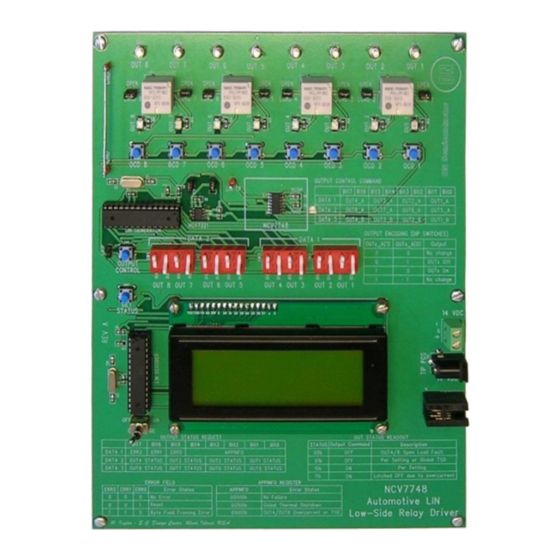
Figure 1. NCV7748 Evaluation Board
Fault
Figure 2. 1.5 W Output Drivers
Figure 3. 0.8 W Output Drivers
1
www.onsemi.com
41 V
(Typ)
1.5 W
(Typ)
Over Current
41 V
(Typ)
0.8 W
(Typ)
Thermal Shutdown
Over Current
Open Load
Publication Order Number:
EVBUM2484/D
OUT1
OUT2
OUT3
OUT5
OUT6
OUT7
OUT4
OUT8
Advertisement

Related Manuals for ON Semiconductor NCV7748


Summary of Contents for ON Semiconductor NCV7748
- Page 1 This evaluation board is intended for evaluation of the output drivers, and highlights many of the features of the device. The NCV7748 has two types of low-side drivers. One is intended to run outside of the module and the other is targeted for use inside the module.
- Page 2 The through a 30 kW resistor in series with a diode and its read NCV7748 is the slave and receives its commands from an capability is filtered to an internal RxD comparator. 30 kW...
- Page 3 A jumper is included to maintain output control to avoid response. going to sleep after the NCV7748 “Time to go to sleep” • Display of Sleep Mode electrical parameter. Pushbuttons are included for After timeout.
- Page 4 NCV7748GEVB User Interface Locations Figure 5 shows all the user interface locations. This lists all the user options available on the evaluation board. 1. OUT1−8 External Post Connections 8. LOOP Jumper for Continuous Operation 2. External Relay Jumpers without Four Second Timeout 3.
-
Page 5: Operational Guidelines
4. The splash screen will be shown (see Figure 6). and stop on OUT8 until the NCV7748 device times out and 5. Move the DEMO MODE toggle switch to the ON OUT8 will also turn off. - Page 6 NCV7748GEVB Output Control Command Bit7 Bit6 Bit5 Bit4 Bit3 Bit2 Bit1 Bit0 DATA_1 OUT4_A OUT3_A OUT2_A OUT1_A DATA_2 OUT8_A OUT7_A OUT6_A OUT5_A DATA_3 OUT4_B OUT3_B OUT2_B OUT1_B Output Encoding (DIP Switches) Figure 8. OUTPUT CONTROL DIP Switches OUTx_A[1] OUTx_A[0] Output (All Outputs On) No Change OUT x Off...
-
Page 7: Get Status
Figure 14. Output Status and Error Reporting Decoding Open Load pin of the NCV7748 device. Jumpers are include for the TxD Open load conditions are reported in the status reporting and RxD pins with and adjacent LIN connection pin for OUT4 and OUT8. - Page 8 NCV7748GEVB SCHEMATIC Figure 15. Evaluation Board Schematic (1 of 2) www.onsemi.com...
- Page 9 NCV7748GEVB Figure 16. Evaluation Board Schematic (2 of 2) www.onsemi.com...
- Page 10 NCV7748GEVB Figure 17. Printed Circuit Board www.onsemi.com...
-
Page 11: Bill Of Materials
LIN Bus Test Point − − KEYSTONE 5010 ELECTRONICS TP22, TP23 GND Test Points − − KEYSTONE 5010 ELECTRONICS NCV7748 LIN Relay Driver − − SOIC14_N ON Semiconductor NCV7748D2R2G NCV4274A 5 V Regulator − − DPAK3_SMD ON Semiconductor NCV4274ADT50RKG 7407 Open-collector Hex −... - Page 12 FDA Class 3 medical devices or medical devices with a same or similar classification in a foreign jurisdiction or any devices intended for implantation in the human body. Should Buyer purchase or use ON Semiconductor products for any such unintended or unauthorized...
Need help?
Do you have a question about the NCV7748 and is the answer not in the manual?
Questions and answers