Table of Contents
Advertisement
Quick Links
NCV7381A0V2GEVB
NCV7381AGEVK
NCV7381 FlexRay
Transceiver Evaluation
Board User's Manual
INTRODUCTION
T h e
N C V 7 3 8 1 A 0 V 2 G E V B
NCV7381AGEVK evaluation kit provides flexible and convenient
platform to evaluate, characterize and verify the operation of the
NCV7381ADP0R2G FlexRay transceivers.
DESCRIPTION
The NCV7381 is a single−channel FlexRay transceiver compliant
with the FlexRay Electrical Physical Layer Specification Rev. 3.0.1,
capable of communicating at speeds of up to 10 Mbit/s. It provides
differential transmit and receive capability between a wired FlexRay
communication medium on one side and a protocol controller and
a host on the other side.
NCV7381 mode control functionality is optimized for nodes
permanently connected to car battery.
Additional details can be found in the NCV7381 datasheet.
The NCV7381A0V2GEVB Evaluation board is a reference design
for stand−alone 2−channel FlexRay node. The board is intended to
give designers easy, quick and convenient means for evaluation of
NCV7381 FlexRay transceiver. The design incorporates complete
node solution with possibility of modifications and small board size.
A set of two boards allows users to quickly start with the transceiver
evaluation. The MCU is preprogrammed with simple mode control
and FlexRay communication. The MCU firmware can be freely
modified and reprogrammed if needed.
BOARD HARDWARE
The evaluation board consists of an MCU with integrated 2−channel
FlexRay communication controller interconnected with two separate
FlexRay transceivers (NCV7381), two switchable voltage regulators
and peripherals. The board is ready for various modifications of power
supply concept and FlexRay bus termination, and allows for simple
extension of the system by unused MCU pins. The USB interface
provides connectivity with standard PC. The address of each board can
be easily modified by address switch what allows for building
complex FlexRay network without need of reprogramming the MCU.
Implemented High Speed CAN interface can be used as a diagnostic
interface in a network built from several nodes. For evaluation
purposes the NCV7381 evaluation board is populated with several
LEDs and most of the transceiver signals are easily accessible to
oscilloscope probes.
© Semiconductor Components Industries, LLC, 2018
June, 2018 − Rev. 0
)
e v a l u a t i o n
b o a r d
a n d
1
www.onsemi.com
EVAL BOARD USER'S MANUAL
NCV7381 Pin Connections
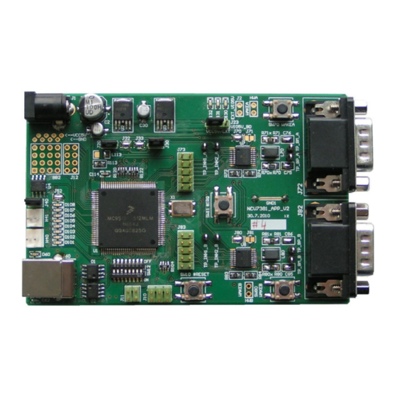
Figure 1. NCV7381A0V2GEVB
Evaluation Board
GENERAL FEATURES
FlexRay Transceiver
•
Two separate FlexRay channels with
NCV7381 transceiver compliant with the
FlexRay Electrical Physical Layer Specifi-
cation Rev. 3.0.1
•
Reconfigurable bus termination − End
node/Middle node
•
Common mode Choke and additional ESD
protection footprint
•
SUBD−9 connectors − FlexRay bus
•
Local Wake−up switch
Publication Order Number:
EVBUM2571/D
Advertisement
Table of Contents

Subscribe to Our Youtube Channel
Related Manuals for ON Semiconductor FlexRay NCV7381 Series


Summary of Contents for ON Semiconductor FlexRay NCV7381 Series
- Page 1 NCV7381A0V2GEVB NCV7381AGEVK NCV7381 FlexRay Transceiver Evaluation Board User's Manual www.onsemi.com INTRODUCTION EVAL BOARD USER’S MANUAL T h e N C V 7 3 8 1 A 0 V 2 G E V B e v a l u a t i o n b o a r d a n d NCV7381AGEVK evaluation kit provides flexible and convenient...
-
Page 2: Getting Started
NCV7381A0V2GEVB Other • • Two Automotive Voltage regulators with Inhibit 16-bit MC9S12XF family MCU with integrated function (Input battery voltage up to 42 V) FlexRay Communication Controller (Protocol • Power supplies voltage monitoring Specification Rev. 2.1) • Integrated CAN 2.0 A, B Controller •... - Page 3 NCV7381A0V2GEVB Operating Modes Channel A and B. Press and hold the pushbutton for The nodes can operate in two different operating modes: approximately 2 seconds to cycle between the indication • Normal mode − all the nodes continuously modes. • communicate over the FlexRay bus FlexRay communication indication –...
-
Page 4: Board Overview
NCV7381A0V2GEVB BOARD OVERVIEW Legend: 1. Power supply input connector 9. FlexRay BD signals test points (Channel A) 2. Aux digital I/O connector 10. FlexRay BD signals test points (Channel B) 3. CAN backbone connector 1 11. MCU Reset pushbutton switch 4. - Page 5 NCV7381A0V2GEVB FlexRay BD Digital Signals Test Points Headers These headers are intended to be used as a test points for digital probes. Headers contain all FlexRay BD digital input and output signals. Test points for both FlexRay channel A and channel B are PCB1 PCB2 PCB3...
- Page 6 NCV7381A0V2GEVB JUMPERS AND DEFAULT CONFIGURATION Figure 12. Jumpers and Soldering Straps Table 2. 2−PIN JUMPER Table 3. 2−PIN JUMPER Open 1 2 3 Open Closed Closed position 1−2 Closed position 2−3 Table 4. JUMPERS CONFIGURATION Jumper Function Configuration Description Default MCU VCC 5 V State Open Controlled by bd_INH1_x...
-
Page 7: Switches And Pushbuttons
NCV7381A0V2GEVB Table 4. JUMPERS CONFIGURATION (continued) Jumper Function Configuration Description Default General purpose LED Open LEDs Disabled Closed Closed LEDs Enabled Bus Driver VBAT supply (Ch A) Open BD VBAT Disconnected Closed Closed BD VBAT Connected Bus Driver VBUF supply (Ch A) Open Open BD VBUF Disconnected... - Page 8 NCV7381A0V2GEVB 0 1 2 3 4 5 6 7 MCU External Interrupt Pushbutton Switch The MCU interrupt module supports one maskable interrupt input. This input is connected to SW11. Local Wake−up Pushbutton Switch The NCV7381 FlexRay transceiver supports Local Wake−up event detection. If a falling edge is recognized on Figure 14.
-
Page 9: Typical Application Diagram
NCV7381A0V2GEVB PROGRAMMING/ SWITCHES DEBUG INTERFACE INTERFACE BACKBONE CLOCK LED’s EXTERNAL AUX I/O PINS RESET MC9S12XF512MLM FlexRay CC POWER SUPPLIES AUX OUTPUTS FlexRay CC A FlexRay CC B MCU & FR BD IO VIO 3V3 FR BD VCC NCV7381 NCV7381 VCC 5V FlexRay BD A FlexRay BD B PASSIVE NETWORK... -
Page 10: Power Supply
NCV7381A0V2GEVB Table 5. RECOMMENDED EXTERNAL COMPONENTS FOR THE APPLICATION DIAGRAM Component Function Min. Typ. Max. Unit Decoupling capacitor on battery line, ceramic VBAT Decoupling capacitor on V supply line, ceramic Decoupling capacitor on V supply line, ceramic Pull−up resistor on WAKE pin WAKE1 Serial protection resistor on WAKE pin WAKE2... - Page 11 NCV7381A0V2GEVB Standard termination that have the maximum electrical distance on the bus. The Recommended bus split termination is shown in the sum of termination resistors values should match the Figure 19. Considering passive network, without active nominal cable impedance. At other nodes a high−ohmic split stars, proper termination should be applied at the two nodes termination should be applied.
- Page 12 The PEmicro HCS12(X) Microcontrollers (Classic IDE) v5.2 USB Multilink interface is directly supported. (http://www.nxp.com/) can be used for programming and (http://www.onsemi.com/). NOTE: The NCV7381A EVB firmware can be downloaded from ON Semiconductor web site Figure 24. CodeWarrior Development Studio www.onsemi.com...
- Page 13 NCV7381A0V2GEVB www.onsemi.com...
- Page 14 NCV7381A0V2GEVB Figure 26. PCB Top Assembly Drawing Figure 27. PCB Bottom Assembly Drawing www.onsemi.com...
- Page 15 NCV7381A0V2GEVB Figure 28. PCB Top Composite Drawing Figure 29. PCB Bottom Composite Drawing (Mirrored) www.onsemi.com...
- Page 16 0.25 mm (9.842 mil) REFERENCES [3] FlexRay Consortium. FlexRay Communications System − Physical Layer EMC Measurement Specification, V3.0.1., [1] ON Semiconductor. NCV7381/D, Product Datasheet, October 2010 Rev. 4, April 2018, www.onsemi.com [2] FlexRay Consortium. FlexRay Communications System − Electrical Physical Layer Specification, V3.0.1., October 2010 FlexRay is a registered trademark of Daimler Chrysler AG.
- Page 17 LIMITATIONS OF LIABILITY: ON Semiconductor shall not be liable for any special, consequential, incidental, indirect or punitive damages, including, but not limited to the costs of requalification, delay, loss of profits or goodwill, arising out of or in connection with the board, even if ON Semiconductor is advised of the possibility of such damages. In no event shall ON Semiconductor’s aggregate liability from any obligation arising out of or in connection with the board, under any theory of liability, exceed the purchase price paid for the board, if any.
Need help?
Do you have a question about the FlexRay NCV7381 Series and is the answer not in the manual?
Questions and answers