Table of Contents
Advertisement
Available languages
Available languages
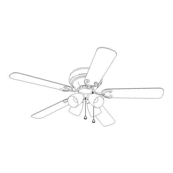
ITEM #18037
18038
CHESHIRE II CEILING FAN
Harbor Breeze® is a registered trademark
of LF, LLC. All Rights Reserved.
MODEL #CSD52FBZ5C4S
CSD52BNK5C4S
español p. 17
E124404
Questions, problems, missing parts? Before returning to your retailer, call our customer
service department at 1-800-527-1292, 8:30 a.m.-5 p.m., CST,
Monday-Friday.
1
Advertisement
Chapters
Table of Contents

Subscribe to Our Youtube Channel
Related Manuals for Harbor Breeze CHESHIRE II CSD52FBZ5C4S


Summary of Contents for Harbor Breeze CHESHIRE II CSD52FBZ5C4S
- Page 1 ITEM #18037 18038 CHESHIRE II CEILING FAN Harbor Breeze® is a registered trademark of LF, LLC. All Rights Reserved. MODEL #CSD52FBZ5C4S CSD52BNK5C4S español p. 17 E124404 Questions, problems, missing parts? Before returning to your retailer, call our customer service department at 1-800-527-1292, 8:30 a.m.-5 p.m., CST,...
-
Page 2: Table Of Contents
TABLE OF CONTENTS Safety Information ......………………………………………………………..….3 Package Contents ......…………………………………………………………..4 Hardware Contents ......…………………………………………………...5 Preparation ........….…………………..……………………….…..5 - 6 Initial Installation ..........……………………...………....6 - 7 Wiring ....................……......8 - 9 Final Installation ....………………….………….............9 - 12 Using Fan Without Light Kit (Optional) ..................12 Fan Operation ..........……………………………......12 - 13 Care and Maintenance .......………………………..………...…..…....13 Troubleshooting... -
Page 3: Safety Information
SAFETY INFORMATION READ AND SAVE THESE INSTRUCTIONS Please read and understand this entire manual before attempting to assemble, install or operate the product. If you have any questions regarding the product, please call customer service at 1-800-527-1292, 8:30 a.m.-5:00 p.m., CST, Monday-Friday. 1. -
Page 4: Package Contents
PACKAGE CONTENTS Part Description Quantity Motor Housing Mounting Bracket Extra Switch Housing Motor Assembly Light Kit Fitter Glass Shade Blade Arm Blade Candelabra Base Bulb Pull Chain Extension (in hardware pack) Plastic Lock Tab Socket Ring (attached to light kit fitter) IMPORTANT REMINDER: You must use the parts provided with this fan for proper installation and safety. -
Page 5: Hardware Contents
HARDWARE CONTENTS Part Description Quantity Part Shown to Size Motor Screw (10 in motor; 1 in hardware pack) 3/16 Blade Screw (in hardware pack) 5.4M/M Lock Washer (10 in motor; 1 in hardware pack) Blade Washer (in hardware pack) E3 Wire Connector (in hardware pack) Motor Housing Mounting Screw (attached to mounting bracket) PREPARATION... -
Page 6: Initial Installation
PREPARATION Bulbs Required (included): 4 candelabra base 60 watt max. bulbs A-15 DANGER: When using an existing outlet box, make sure the outlet box is securely attached to the building structure and can support the full weight of the fan. Failure to do this can result in serious injury or death. - Page 7 INITIAL INSTALLATION Fig. 4 4. Remove motor screws (AA) and lock washers (CC) from underside of motor--save to attach blade arms (G) later on. If there are also plastic motor blocks, discard them at Motor this time. (Fig. 4) Hardware Used Motor Screw x 10 5.4 M/M Lock Washer...
-
Page 8: Wiring
WIRING WARNING: To reduce the risk of fire, electrical shock, or personal injury, wire connectors provided with this fan are designed to accept only one 12 gauge house wire and two lead wires from the fan. If your house wire is larger than 12 gauge or there is more than one house wire to connect to the two fan lead wires, consult an electrician for the proper size wire connectors to use. -
Page 9: Final Installation
WIRING Fig. 2 2. Wrap electrical tape around each wire connector (EE) down to the wire as shown in Fig. 2. WARNING: Make sure no bare wire or wire strands are visible after making connections. Place green and white connections on opposite side of box from the black and blue (if applicable) connections. - Page 10 FINAL INSTALLATION Fig. 2 2. Partially insert three blade screws (BB), along with three blade washers (DD), to attach one blade arm (G) to a blade (H). Then, tighten each blade screw (BB), starting with the one in the middle (Fig. 2) Repeat with remaining blades (H).
- Page 11 FINAL INSTALLATION Fig. 5 5. Gently push wires and molex connections into switch Switch housing plate. Align fan pull chain slot with fan pull Housing chain and attach light kit fitter (B) to fan with screws that Plate were removed in the previous step. Use a Phillips screwdriver to secure all three screws.
-
Page 12: Using Fan Without Light Kit (Optional)
FINAL INSTALLATION Fig. 9 8. The pull chain extensions (J) supplied in one of the hardware packs or custom pull chain extensions (not included) may be attached to fan and light pull chains. (Fig. 8) (For Fan) (For Light) USING FAN WITHOUT LIGHT KIT (OPTIONAL) Fig. -
Page 13: Care And Maintenance
FAN OPERATION Fig. 2 2. The pull chain in the center is used to turn the lights ON or OFF. (Fig. 2) Fig. 3 3. Use the fan reverse switch, located on the light kit fitter (E), to optimize your fan for seasonal performance. -
Page 14: Troubleshooting
TROUBLESHOOTING WARNING: Before beginning work, shut off the power supply to avoid electrical shock. Problem Possible Cause Corrective Action Fan does not move. 1. Reverse switch not engaged. 1. Push switch firmly either left or right. 2. Power is off or fuse is blown. 2. -
Page 15: Warranty
WARRANTY LIMITED LIFETIME WARRANTY: Litex Industries warrants this fan to be free from defects in workmanship and materials present at time of shipment from the factory for Lifetime limited from the date of purchase. This warranty applies only to the original purchaser. Litex Industries agrees to correct any defect at no charge or, at our option, replace the ceiling fan with a comparable or superior model. -
Page 16: Replacement Parts List
REPLACEMENT PARTS LIST For replacement parts, call our customer service department at 1-800-527-1292, 8:30 a.m.-5:00 p.m., CST, Monday-Friday. When ordering parts, please have the Model # or Item # of the fan available, which can be found on page 1. Part Description Motor Housing... - Page 17 ARTICULO #18037 18038 VENTILADOR DE TECHO CHESHIRE II Harbor Breeze® es marca registrada de LF, LLC. Reservados todos los derechos. MODELO #CSD52FBZ5C4S CSD52BNK5C4S E124404 ¿Preguntas, problemas, faltan piezas? Antes de regresar a la tienda, llame o póngase en contacto con nuestro departamento de servicio al cliente al 1-800-527-1292, de 8:30 a.m. a...
- Page 18 INDICE DE MATERIAS Información de seguridad ..……………………………………………......19 Contenido del paquete ....………………………………………………………..20 Contenido de artículos de ferretería ....………………………………....21 Preparación .......................21 - 22 Instalación inicial ..........……………………………………..22 - 23 Conexión de los cables .........…………………………………….24 - 25 Instalación final ....……………….…………….…….………………….…....26 - 28 Uso del ventilador sin el juego de luz (opcional) .................28 Funcionamiento del ventilador ....…..............28 - 29...
-
Page 19: Información De Seguridad
INFORMACION DE SEGURIDAD POR FAVOR LEA Y GUARDE ESTAS INSTRUCCIONES Por favor lea el instructivo entero antes de tratar de ensamblar, instalar o hacer funcionar el producto. Si tiene alguna pregunta acerca del producto, por favor llame al servicio al cliente al 1-800-527-1292, de 8:30 a.m. -
Page 20: Contenido Del Paquete
CONTENIDO DEL PAQUETE Pieza Descripción Cantidad Bastidor del motor Soporte de montaje Cubierta de la caja del interruptor adicional (para uso sin el juego de luz) Unidad del motor Conectador para el juego de luz Pantalla de vidrio Brazo para la paleta Paleta Bombilla de base candelabro Extensión para la cadena de en-... -
Page 21: Contenido De Artículos De Ferretería
CONTENIDO DE ARTICULOS DE FERRETERIA Se muestra la pieza Pieza Descripción Cantidad en tamaño natural Tornillo del motor (10 en el motor; 1 en el paquete de artículos de ferretería) Tornillo para la paleta 4,76 mm (en paquete de artículos de ferretería) Arandela de seguridad 5,4 M/M (10 en el motor;... -
Page 22: Instalación Inicial
PREPARACION Bombillas necesarias (incluidas): 4 bombillas de base candelabro de 60 vatios máx. A-15 PELIGRO: Cuando utilice una caja de salida existente, asegúrese de que la caja de salida esté firmemente sujetada a la estructura del edificio para que pueda sostener el peso total del ventilador. - Page 23 INSTALACION INICIAL 4. Saque los tornillos del motor (AA) y las Fig. 4 arandelas de seguridad (CC) del lado inferior del motor--guárdelos para sujetar los brazos para las paletas (G) más adelante. Si hay también soportes de plástico del motor, deséchelos motor soportes de plástico en este momento.
-
Page 24: Conexión De Los Cables
CONEXION DE LOS CABLES ADVERTENCIA: Para reducir el riesgo de incendio, choque eléctrico o daño corporal, los conectores para cable provistos con este ventilador son diseñados para aceptar sólo un cable de calibre 12 de la casa y dos cables principales del ventilador. - Page 25 CONEXION DE LOS CABLES VENTILADOR Y LUZ CONTROLADOS POR DOS 1C. VENTILADOR Y LUZ CONTROLADOS POR INTERUPTORES DE PARED DOS INTERRUPTORES DE PARED: Si usted piensa Fig. 1C NEGRO (INTERRUPTOR DE PARED) controlar la luz y el ventilador con interruptores 120 V cables (INTERRUPTOR DE PARED para la LUZ) de corriente...
-
Page 26: Instalación Final
INSTALACION FINAL Fig. 1 1. Temporalmente levante el bastidor del motor (A) al soporte de montaje (B) para determinar cuáles dos tornillos para montaje del bastidor del motor (FF) se alinean con los agujeros con ranura en el bastidor del motor (A) y afloje dichos tornillos (FF) parcialmente. - Page 27 INSTALACION FINAL Fig. 4 4. Si desea UTILIZAR el juego de luz, quite tres placa de la tornillos de la placa de la caja del interruptor del lado caja del inferior del motor. Localice los cables NEGRO y interruptor BLANCO en la placa de la caja del interruptor etiquetados "FOR LIGHT"...
-
Page 28: Uso Del Ventilador Sin El Juego De Luz (Opcional)
INSTALACION FINAL Fig. 9 8. Las extensiones para las cadenas de encendido (J) provistas en uno de los paquetes de artículos de ferretería o las extensiones para cadena de encendido hechas a medida (no incluidas) se pueden fijar a las cadenas de encendido para el (para el ventilador y la luz (Fig. -
Page 29: Cuidado Y Mantenimiento
FUNCIONAMIENTO DEL VENTILADOR Fig. 2 2. La cadena de encendido localizada en el centro se usa para ENCENDER o APAGAR las luces. (Fig. 2) 3. Use el interruptor de reversa, localizada en el conectador para el juego de luz (E), para optimizar el Fig. -
Page 30: Localización De Fallas
LOCALIZACION DE FALLAS ADVERTENCIA: Antes de empezar cualquier trabajo, corte el suministro de electricidad para evitar un choque eléctrico. Problema Causa posible Acción correctiva El ventilador no se 1. El interruptor de reversa no está 1. Mueva el interruptor firmemente mueve. -
Page 31: Garantía
GARANTIA GARANTIA LIMITADA DE POR VIDA: Litex Industries garantiza que este ventilador está libre de defectos de mano de obra y de materiales desde la fecha de salida de la fábrica por el tiempo de por vida limitada a partir de la fecha de compra. Esta garantía sólo se aplica al comprador original. -
Page 32: Lista De Piezas De Repuestos
LISTA DE PIEZAS DE REPUESTO Para piezas de repuesto, llame a nuestro departamento de servicio al cliente al 1-800-527-1292, de 8:30 a.m. a 5:00 p.m., hora central, de lunes a viernes. Al pedir piezas, por favor tenga listo el No. de modelo o No. de artículo del accesorio para iluminación, que se pueden encontrar en la página 17).
Need help?
Do you have a question about the CHESHIRE II CSD52FBZ5C4S and is the answer not in the manual?
Questions and answers