Table of Contents
Advertisement
Quick Links
Harbor Breeze® is a registered trademark
of LF, LLC. All Rights Reserved.
ATTACH YOUR RECEIPT HERE
Serial Number
Questions, problems, missing parts? Before returning to your retailer, call our customer
service department at
5 p.m., EST, Friday.
EB14636
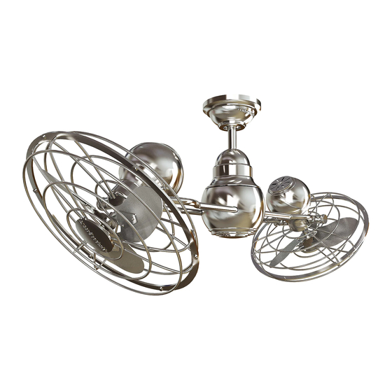
BELCARRA CEILING FAN
Purchase Date
1-800-643-0067, 8 a.m. - 6 p.m., EST, Monday - Thursday, 8 a.m. -
Lowes.com/harborbreeze
1
ITEM
#0428798
0647022
MODEL
#CE-JP13EB6RC
CE-JP13BNK6RC
Français p. 16
For
Damp Location
E192641
Advertisement
Table of Contents

Related Manuals for Harbor Breeze BELCARRA CE-JP13BNK6RC


Summary of Contents for Harbor Breeze BELCARRA CE-JP13BNK6RC
- Page 1 ITEM #0428798 0647022 BELCARRA CEILING FAN MODEL #CE-JP13EB6RC Harbor Breeze® is a registered trademark CE-JP13BNK6RC of LF, LLC. All Rights Reserved. Français p. 16 Damp Location ATTACH YOUR RECEIPT HERE E192641 Serial Number Purchase Date Questions, problems, missing parts? Before returning to your retailer, call our customer service department at 1-800-643-0067, 8 a.m.
-
Page 2: Table Of Contents
TABLE OF CONTENTS Safety Information ........................2 Package Contents ........................4 Hardware Contents ...........................5 Preparation ...........................5 Initial Installation ........................6 Fan Mounting ........................7 Wiring ...........................9 Final Installation ........................11 Automated Learning Process/Activating Code ..............12 Operating Instructions for Remote Control and Fan ............13 Care and Maintenance .......................13 Troubleshooting........................14 Limited Lifetime Warranty ....................15 Replacement Parts List .......................15... - Page 3 SAFETY INFORMATION DANGER If using this fan in a DAMP location, this fan must be connected to a supply circuit that is protected by a Ground Fault Circuit Interrupter (GFCI) to reduce the risk of personal injury, electrical shock or death. WARNINGS To reduce the risk of fire, electrical shock or personal injury, mount fan to outlet box marked "ACCEPTABLE FOR FAN SUPPORT OF 35 LBS.
-
Page 4: Package Contents
PACKAGE CONTENTS PART DESCRIPTION QUANTITY Downrod Canopy Mounting Bracket Motor Assembly Pin (preassembled) Clip (preassembled) Canopy Mounting Screw (preassembled) Canopy Cover Remote Control Transmitter Remote Control Receiver Battery Yoke Cover Safety Cable (preassembled) IMPORTANT REMINDER: You must use the parts provided with this fan for proper installation and safety. -
Page 5: Hardware Contents
HARDWARE CONTENTS (shown actual size) E3 Wire Connector Qty. 10 PREPARATION Before beginning assembly of product, make sure all parts are present. Compare parts with package contents list and hardware contents list. If any part is missing or damaged, do not attempt to assemble the product. -
Page 6: Initial Installation
INITIAL INSTALLATION Turn off circuit breakers and wall switch to the fan supply line leads. DANGER: Failure to disconnect power supply prior to installation may result in serious injury or death. This fan can only be mounted with the downrod in the motor assembly (D). -
Page 7: Fan Mounting
INITIAL INSTALLATION Secure mounting bracket (C) to outlet box (not included) using screws, spring washers and flat washers provided with the outlet box. *NOTE: It is very important you use the proper hardware when installing the mounting bracket (C) as this will support the fan. FAN MOUNTING Remove pin (E) and clip (F) from yoke at top of motor assembly (D) and partially loosen... - Page 8 FAN MOUNTING Slip downrod (A) into yoke, align holes and re-install pin (E) and clip (F). Tighten set screws and nuts in yoke. Slide yoke cover (L) down until it rests on top of motor assembly (D). Screw Depending on the length of downrod you use, you may need to cut the lead wires back to simplify the wiring.
-
Page 9: Wiring
FAN MOUNTING Slide downrod (A) through opening in mounting bracket (C) and then turn the downrod (A) so the straight edges at the top of the downrod (A) align with the sides of the mounting bracket (C). Pull down firmly on the downrod (A) until it sits securely inside the mounting bracket (C). - Page 10 WIRING Make the necessary wiring connections for remote WHITE SUPPLY WIRE control operation according to Fig. 1. For each wire GROUND (GREEN connection, use one of the wire connectors (AA), BLACK SUPPLY WIRE OR BARE) making sure to screw wire connector (AA) on in a BLUE clockwise direction.
-
Page 11: Final Installation
FINAL INSTALLATION Locate two canopy mounting screws (G) on underside of mounting bracket (C) and remove canopy mounting screw (G) closest to the open end of the mounting bracket (C). Partially loosen the other canopy mounting screw (G). Lift canopy (B) to mounting bracket (C). -
Page 12: Automated Learning Process/Activating Code
AUTOMATED LEARNING PROCESS/ACTIVATING CODE Remove battery cover from back side of remote Code Switches control transmitter (I). Set the code on the remote control transmitter (I) by sliding code switches 1 through 4 to your choice of up or down position. (Factory setting is all up. -
Page 13: Operating Instructions For Remote Control And Fan
OPERATING INSTRUCTIONS FOR REMOTE CONTROL AND FAN Operation buttons on the panel of the remote control transmitter (I) : Button turns the 2 smaller fans to HIGH speed Button turns the 2 smaller fans to MEDIUM speed Button turns the 2 smaller fans to LOW speed Button turns the 2 smaller fans OFF Button... -
Page 14: Troubleshooting
TROUBLESHOOTING WARNING: Before beginning work, shut off the power supply to avoid electrical shock. PROBLEM POSSIBLE CAUSE CORRECTIVE ACTION Fan does not 1. Power is off or fuse is blown. 1. Turn power on or check fuse or move. breaker. 2. -
Page 15: Limited Lifetime Warranty
0647022-B 0647022-C Mounting Bracket 0428798-C 0428798-E 0647022-E 0647022-F Clip 0428798-F Canopy Mounting Screw 0428798-G 0647022-G 0647022-H Canopy Cover 0428798-H Yoke Cover 0647022-L 0428798-L Printed in China Harbor Breeze® is a registered trademark of LF, LLC. All Rights Reserved. Lowes.com/harborbreeze KHLI1410...
Need help?
Do you have a question about the BELCARRA CE-JP13BNK6RC and is the answer not in the manual?
Questions and answers