Table of Contents
Advertisement
Quick Links
Advertisement
Table of Contents

Related Manuals for Sun Microsystems Cobalt LX50


Summary of Contents for Sun Microsystems Cobalt LX50
- Page 1 Sun Cobalt™ LX50 Server User Guide...
- Page 2 Copyright © 2002 Sun Microsystems, Inc. 4150 Network Circle, Santa Clara, California 95054, U.S.A. Tous droits réservés. Sun Microsystems, Inc. détient des droits de propriété intellectuelle sur la technologie réunie dans le produit qui est décrit par ce document. Ces droits de propriété...
-
Page 3: Preface
You must be root to do this; Terms to be emphasized; To delete a file, type rm filename . Variables that you replace with a real value; What you type boldface machine_name% su courier font User Guide—Sun Cobalt LX50 Server... -
Page 4: Related Documentation
Ordering Sun Documents The SunDocs program provides more than 250 manuals from Sun Microsystems, Inc. If you are in the United States, Canada, Europe or Japan, you can purchase documentation sets or individual manuals by using this program. For a list of documents and how to order them, see the catalog section of the SunExpress™ Internet site at http://store.sun.com . -
Page 5: Table Of Contents
Preinstalled Software ....................1–6 Installation Quickstart ..................... 1–7 2 Installing the Server in a Rack 2–1 Decide Where to Configure the Sun Cobalt LX50 server ........2–1 Precautions ......................2–2 Introduction ......................2–3 Installing the Server Using the Bracket Kit ............2–4 Required Tools .................... - Page 6 Front Panel LEDs and Pushbuttons ................ 3–1 LEDs ........................ 3–2 Pushbuttons ...................... 3–2 Rear Panel LEDs ..................... 3–3 4 Powering On and Configuring the Server 4–1 Setting the Jumper Positions ................... 4–1 Powering On ......................4–1 Clearing CMOS ...................... 4–2 User Guide—Sun Cobalt LX50 Server...
- Page 7 Floppy/CD-ROM Combo Module ..............5–5 Memory ......................5–6 Power Supply Unit ..................5–7 Hard Disk Drives ..................5–8 Air Baffle ....................... 5–10 Removal ....................5–10 Installation ....................5–10 Fan Module ....................5–11 PCI Cards ..................... 5–13 Battery ......................5–14 User Guide—Sun Cobalt LX50 Server...
- Page 8 Segment B: 64 bit, 66 MHz, 3.3 V, (P64-B) supporting the following configuration ................7–2 Segment C: 64 bit, 66/33 MHz, 3.3 V (P64-C) supporting the following device ..................7–2 LPC: (Low Pin Count) bus segment with two embedded devices ....7–2 viii User Guide—Sun Cobalt LX50 Server...
- Page 9 Server Management Features .................. 7–4 Power Supply ......................7–5 Dimensions ......................7–5 Weight ........................7–5 Mounting Options ....................7–5 Environmental ......................7–6 Ambient Temperature ..................7–6 Relative Humidity .................... 7–6 Vibration ......................7–6 Shock ........................ 7–6 Acoustics ......................7–6 User Guide—Sun Cobalt LX50 Server...
- Page 10 Contents User Guide—Sun Cobalt LX50 Server...
-
Page 11: Figures
The Sun Cobalt LX50 Server ........ - Page 12 Location of Front-Panel ID LED ..........6-6 User Guide—Sun Cobalt LX50 Server...
- Page 13 Video Modes ..............7-3 User Guide—Sun Cobalt LX50 Server...
- Page 14 User Guide—Sun Cobalt LX50 Server...
-
Page 15: Introducing The Sun Cobalt Lx50 Server
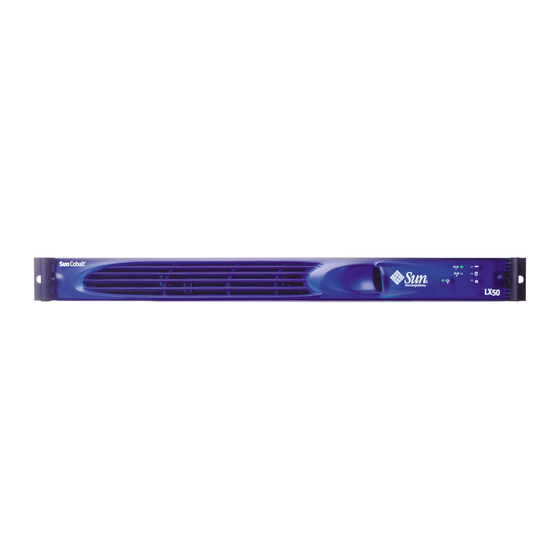
Overview of the Sun Cobalt™ LX50 Server The Sun Cobalt LX50 server, shown in Figure 1, is a single- or dual-processor server in a 1 rack unit (1RU) chassis (1 RU is 1.75” of vertical rack space). The bezel shown in the figure is installed by the user. - Page 16 High-density computing environments (scientific research, EDA, financial services, and so on). • Running custom designed applications for telecommunication carriers and Internet service providers. The Sun Cobalt LX50 server has the following features (see Chapter 7, “Specifications,” for more details): • Single or dual processors.
-
Page 17: Contents Of The Ship Kit
Contents of the Ship Kit Contents of the Ship Kit The Sun Cobalt LX50 server is supplied with the components shown in Table 3 Table 3. Contents of the Ship Kit Item Part Number Quantity Delivery Sun Cobalt LX50 Documents on CD:... -
Page 18: Replaceable Components
Chapter 1: Introducing the Sun Cobalt LX50 server Replaceable Components The replaceable components on the Sun Cobalt LX50 server are shown in Table 4. Some of the components are considered to be customer-replaceable units (CRUs), and some are considered to be field-replaceable units (FRUs), replaceable only by an authorized Sun Microsystems, Inc. -
Page 19: Optional Rj-45 To Db9 Serial Adapter Kit
This cable is wired for connection to the COM port of a laptop or computer that connects to the front EMP port of the Sun Cobalt LX50 server. See “Front RJ-45 Serial 2 Connector” on page 2-27 for more information on how to use this adapter cable. -
Page 20: Preinstalled Software
Chapter 1: Introducing the Sun Cobalt LX50 server Preinstalled Software The Sun Cobalt LX50 server comes preinstalled with Sun Linux 5.0, as well as the following applications: • MySQL server and client • Apache In addition, the following applications are files or RPMs included under the... -
Page 21: Installation Quickstart
Installation Quickstart Installation Quickstart Table 6 is a simplified summary of the steps you need to follow to install and configure the Sun Cobalt LX50 server. Table 6. Installation Quickstart Procedure Step Task Reference 1 - Install the Hardware Mount server in the rack See Chapter 2, “Installing the Server in a Rack.”... - Page 22 Chapter 1: Introducing the Sun Cobalt LX50 server User Guide—Sun Cobalt LX50 Server...
-
Page 23: Installing The Server In A Rack
If you are going to configure the server after it is mounted in the rack, proceed to the section titled “Precautions” on page 2-2. To configure the Sun Cobalt LX50 server while it is in the rack, it is best to use a laptop to connect to the server Emergency Management Port (EMP) on the front panel of the server. -
Page 24: Precautions
The equipment rack must provide sufficient airflow to the front of the server to maintain proper cooling. It must also include ventilation sufficient to exhaust a maximum of 850 BTUs per hour for a fully loaded Sun Cobalt LX50 server. -
Page 25: Introduction
Introduction Introduction There are two methods for installing the Sun Cobalt LX50 server in a rack: • Bracket Kit (see “Installing the Server Using the Bracket Kit” on page 2-4) This mounting method is quick and easy, but makes it somewhat difficult to service the server. -
Page 26: Installing The Server Using The Bracket Kit
Fastener pack—qty. 1 (see Figure 2) Figure 2. Fastener Pack Contents A. Screw, #10-32 x 1/2-inch—qty. 8 B. Screw, #6-32 x 3/16-inch—qty. 4 C. Screw, #10-32 x 7/8-inch—qty. 2 D. Handle spacers—qty. 2 E. Nut bar—qty. 4 Chassis disks—qty. 2 User Guide—Sun Cobalt LX50 Server... -
Page 27: Mounting In A Four-Post Rack System
3. Slide the bracket as far as it will go toward the front of the chassis. 4. Fasten the bracket to the chassis using screw (D). 5. In the same manner, attach a chassis bracket to the other side of the chassis. User Guide—Sun Cobalt LX50 Server... -
Page 28: Attach Disks To Chassis
2. Install screw (B) and tighten. 3. In the same manner, attach a chassis disk to the opposite side of the chassis. Figure 5. Attaching a Chassis Disk to the Chassis A. Chassis disk B. #6-32 x 3/16-inch screw User Guide—Sun Cobalt LX50 Server... -
Page 29: Attach Brackets To Rear Posts
Align the face of the bracket foot with the edge of the rack post and firmly tighten the screws. Figure 6. Attaching a Rear Bracket to a Rear Post A. #10-32 x 1/2-inch screw with washers B. Nut bar C. Rear bracket User Guide—Sun Cobalt LX50 Server... -
Page 30: Install Chassis In Rack
Slide the chassis toward the rear of the rack until the front of the chassis brackets contact the front posts. Attach the chassis brackets (Figure 8, A) to the front posts (B) using two screws (C) and one nut bar (D) per side. User Guide—Sun Cobalt LX50 Server... - Page 31 Installing the Server Using the Bracket Kit Figure 8. Attaching a Front Bracket to a Front Post A. Chassis bracket B. Front post C. #10-32 x 1/2-inch screw with washers D. Nut bar User Guide—Sun Cobalt LX50 Server...
-
Page 32: Install Chassis Handles
You have completed the installation of your chassis in a four-post rack system. Figure 9. Attaching a Chassis Handle to a Front Post A. Chassis handle B. Spacer C. #10-32 x 7/8-inch screw with washer 2-10 User Guide—Sun Cobalt LX50 Server... -
Page 33: Mid-Mounting In A Two-Post Rack System
5. In the same manner, attach a bracket to the other side of the chassis. Figure 10. Installing a Chassis Bracket in the Mid-mount Position A. Chassis bracket in mid-mount position B. Bracket holes C. Chassis tabs D. #6-32 x 3/16-inch screw User Guide—Sun Cobalt LX50 Server 2-11... -
Page 34: Attach L Brackets To Center Posts
In the same manner, attach an L bracket to the other center post. Figure 11. Attaching an L Bracket to a Center Post A. L bracket B. Screw (supplied by your rack manufacturer) C. Front side of typical right center post 2-12 User Guide—Sun Cobalt LX50 Server... -
Page 35: Install Chassis In Rack
Using the screws (Figure 13, C) supplied with your rack, attach the front of the mounting brackets to the front of the center posts. You have completed the mid-mount installation of your chassis in a two-post rack system. User Guide—Sun Cobalt LX50 Server 2-13... -
Page 36: Installing The Chassis In The Rack
Chapter 2: Installing the Server in a Rack Figure 13. Installing the Chassis in the Rack A. Chassis bracket in mid-mount position B. L bracket C. Screw (supplied by rack manufacturer) 2-14 User Guide—Sun Cobalt LX50 Server... -
Page 37: Front-Mount-Only In A Two-Post Rack System
Remove the Chassis Handles Remove the bezel. Remove two screws from each handle (see Figure 14). Set the handles and screws aside for reattachment later. Figure 14. Removing a Handle from the Chassis User Guide—Sun Cobalt LX50 Server 2-15... -
Page 38: Attach Brackets To Chassis
In the same manner, attach a bracket to the other side of the chassis. Figure 15. Installing a Chassis Bracket in the Front-mount Position A. Chassis bracket in front-mount position B. Bracket holes C. Chassis tabs D. #6-32 x 3/16-inch screw 2-16 User Guide—Sun Cobalt LX50 Server... -
Page 39: Attach L Brackets To Center Posts
In the same manner, attach an L bracket to the other center post. Figure 16. Attaching an L Bracket to a Center Post A. L bracket B. Screw (supplied by rack manufacturer) C. Front flange of typical right center post User Guide—Sun Cobalt LX50 Server 2-17... -
Page 40: Install Chassis In Rack
Slide the chassis toward the rear of the rack until the front of the chassis brackets contact the front of the center posts. Using the fasteners (Figure 18, C) supplied with your rack, attach the front of the mounting brackets to the front of the center posts. 2-18 User Guide—Sun Cobalt LX50 Server... -
Page 41: Installing The Chassis In The Rack
Installing the Server Using the Bracket Kit Figure 18. Installing the Chassis in the Rack A. Chassis bracket in front-mount position B. L bracket C. Screw (supplied by rack manufacturer) User Guide—Sun Cobalt LX50 Server 2-19... -
Page 42: Install Chassis Handles
In the same manner, attach the other handle to the opposite side. Replace the bezel. Figure 19. Attaching a Chassis Handle to a Center Post A. Chassis handle B. Spacer C. #10-32 x 7/8-inch screw with washer 2-20 User Guide—Sun Cobalt LX50 Server... -
Page 43: Installing The Server Using The Slide Rail Kit (Optional)
Installing the Server Using the Slide Rail Kit (Optional) Installing the Server Using the Slide Rail Kit (Optional) The rail kit is an extra cost option, and allows you to install the Sun Cobalt LX50 server in most four-post rack and cabinet systems. -
Page 44: Attach Inside Rails To Chassis
In the same manner, attach the other inside rail to the other side of the chassis. Figure 22. Attaching an Inside Rail to the Chassis A. Inside rail B. #6-32 x 3/16-inch screw C. Attachment hole D. Attachment tab E. Attachment hole for cable manager (available from other suppliers) 2-22 User Guide—Sun Cobalt LX50 Server... -
Page 45: Attach Rail Brackets To Posts
Firmly tighten this screw. 6. Firmly tighten the front screw (G) installed loosely in step 4. In the same manner, attach the other rail assembly to the other side. User Guide—Sun Cobalt LX50 Server 2-23... -
Page 46: Attach A Rail Assembly To A Rear Bracket
Attach the rear end of the outer rail (B) to the rear bracket (A) with at least one screw (C). If possible, attach at two places. 3. In the same manner, attach the other rail assembly to the other side. 2-24 User Guide—Sun Cobalt LX50 Server... -
Page 47: Install The Chassis On The Rails
3. Slide the chassis toward the rear of the cabinet until the rails lock together. Depress and hold down the finger tabs (Figure 27, A) on both extension locks while sliding the chassis toward the rear. User Guide—Sun Cobalt LX50 Server 2-25... - Page 48 Chapter 2: Installing the Server in a Rack Figure 27. Releasing the Extension Locks A. Finger tab on extension lock Slide the chassis all the way into the rack until the chassis handles are against the front posts. 2-26 User Guide—Sun Cobalt LX50 Server...
-
Page 49: Connecting The Cables
Connecting the Cables Connecting the Cables The Sun Cobalt LX50 server has a number of connectors. Some are on the front panel; others are located on the rear panel. This section summarizes the usage of each connector. Front Panel Connectors To access the front panel connectors when a front bezel is installed, grasp the bezel on the right side at the finger hole... -
Page 50: Front Rj-45 Serial 2 Port Adapter Pinout
RI signal. ✍ Note: Sun Microsystems provides an optional RJ-45 to DB9 Serial Adapter Kit (order number X5026A) for purchase. It contains three RJ-45-to-DB9 adapters. They can be plugged into the front or rear EMP connectors. The cables are: •... -
Page 51: Usb Connectors
IEEE 820.3u AutoNegotiation support • Full-duplex support at both 10 Mbps and 100 Mbps operation • Both ports are PXE Boot capable • Low power +3.3 V device (Wake-On-LAN support on both rear panel Ethernet ports) User Guide—Sun Cobalt LX50 Server 2-29... -
Page 52: Ac Power Connector
For serial devices that require a DCD signal, the J6A2 jumper block must be configured as follows: Both jumpers are in positions 2 and 3. Pin 1 is denoted by an arrow directly next to the jumper block. The following diagram provides the J6A2 jumper block pinout for this configuration. 2-30 User Guide—Sun Cobalt LX50 Server... -
Page 53: J6A2 Jumper Block Configured For Dcd Signal (Pin 7 Connected To Dcd)
Pin 7 can be manually configured to support either a DCD or DSR signal by setting the J6A2 jumper block appropriately. On the Sun Cobalt LX50 server, the adapters used for the back connector cannot be used with the front connector, as the pinout for the RJ-45 ports are different. -
Page 54: Usb 3 And Usb 4 Connectors
68-pin connector. Use only shielded Ultra-160 LVDS rated cables for connection to external SCSI drives. Video Connector The Sun Cobalt LX50 server provides an ATI Rage XL PCI graphics accelerator, along with 8 MB of video SDRAM and support circuitry for an embedded SVGA video subsystem. The SVGA subsystem supports a variety of modes, up to 1600 x 1200 resolution in 8/16/24/32 bpp modes under 2D, and up to 1024 x 768 resolution in 8/16/24/32 bpp modes under 3D. -
Page 55: Controls And Indicators
Figure 33. Front Panel Pushbuttons and LEDs (bezel removed) NIC1 LED System Status/Fault LED NIC2 LED Hard Disk Drive Activity LED System ID LED Power LED OM11670D System ID Button Power Button Reset Button NMI Button (recessed, not implemented) User Guide—Sun Cobalt LX50 Server... -
Page 56: Leds
System ID button. This pushbutton toggles the state of the front panel ID LED and the server Main Board ID LED. The Main Board ID LED is visible through the rear of the chassis and allows you to locate a particular server from behind a rack of servers. User Guide—Sun Cobalt LX50 Server... -
Page 57: Rear Panel Leds
Power Supply LED (green/amber). This is a bi-color LED that can be on, off, green, amber, or blinking, or combination thereof. See “Rear Panel Power Supply Status LED” on page 6-4 for more detailed information. User Guide—Sun Cobalt LX50 Server... - Page 58 Chapter 3: Controls and Indicators User Guide—Sun Cobalt LX50 Server...
-
Page 59: Powering On And Configuring The Server
AC power being supplied through the AC power cord. The location of the switch is shown in Figure 35. Figure 35. Power and Reset Switches on the Front Panel Front Panel Power On/Off Switch Reset Switch User Guide—Sun Cobalt LX50 Server... -
Page 60: Clearing Cmos
AC voltage to the equipment. Caution: As shipped, the Sun Cobalt LX50 server does not have Advanced Configuration and Power (ACPI) enabled in the Sun Linux™ 5.0 kernel and, as a result, the front panel power switch operates as a normal power switch. -
Page 61: Bios Setup Utility
Press F2 to enter the BIOS Setup Utility. The main BIOS Setup Utility screen shown in Figure 37 appears. Figure 37. BIOS Setup Utility Main Screen Caution: Changing the BIOS settings may cause undesirable effects, and in some cases may disable the server. Be very careful before changing the BIOS configuration. User Guide—Sun Cobalt LX50 Server... -
Page 62: Default Boot Sequence
To restore all of the default settings, scroll to “Load Setup Defaults” and press Enter, then select Yes at the prompt and press Enter again. Now press F10 to save the settings and exit. When you exit the BIOS setup utility, the bootup process continues. User Guide—Sun Cobalt LX50 Server... -
Page 63: Service Partition
Note : When you select a boot device with the menu shown in Figure 41, it only affects the current boot. Subsequent boots revert to the device stored in the BIOS default settings. Figure 41. Boot Device Selection Menu. User Guide—Sun Cobalt LX50 Server... -
Page 64: Linux Loader (Lilo) Menu Options
Chapter 4: Powering On and Configuring the Server Linux Loader (LILO) Menu Options The bootup process eventually takes you to the Sun Linux loader screen. The Sun Cobalt LX50 server uses the standard LILO boot loader. You initially have four options: •... -
Page 65: Configuring An External Serial Console
Configuring an External Serial Console There are two RJ-45 serial console ports on the Sun Cobalt LX50 server, one on the front panel and one on the rear panel, as shown in Figure 42. You can direct boot messages to a serial console (for example, a laptop running HyperTerminal). - Page 66 Note: The serial port is enabled for all boot options, but the standard Linux console device changes, depending on which boot option is selected (see “Linux Loader (LILO) Menu Options” on page 4-6 for more details). User Guide—Sun Cobalt LX50 Server...
-
Page 67: Using The Service Partition Menu
When you press F4 at the initial bootup screen, the Service Partition Menu appears (see Figure 43). Figure 43. Service Partition Menu There are three main menu items across the top of this screen: • Create Diskettes • System Utilities • Quit to DOS User Guide—Sun Cobalt LX50 Server... -
Page 68: Create Diskettes
Create HSC Diskette: choosing this option creates one diskette that allows you to update the HSC firmware. • Create BMC Diskette: choosing this option creates one diskette that allows you to update the BMC firmware 4-10 User Guide—Sun Cobalt LX50 Server... -
Page 69: System Utilities
Run BMC Firmware Update • Run HSC Firmware Update • Run FRU/SDR Update • Run BIOS Boot Block Update (reboot required) • Run BIOS Update (reboot required) • Reboot to Service Partition • Reboot System User Guide—Sun Cobalt LX50 Server 4-11... -
Page 70: Run System Setup Utility
Chapter 4: Powering On and Configuring the Server Run System Setup Utility The built-in service partition on the hard disk of the Sun Cobalt LX50 server allows you to perform server management, configuration and validation testing. To bring up the service partition, reboot and press the <F4>... - Page 71 PWA Security menu item in the Available Tasks pane of the SSU main window. The main Security window appears (see Figure 48). ✍ Note : This menu allows you to change the security settings without going into the BIOS setup. User Guide—Sun Cobalt LX50 Server 4-13...
- Page 72 To manage the FRUs, double-click the FRU Manager menu item on the Available Tasks pane of the main SSU window. The FRU Manager main window appears, and you can use the menu bar at the top of the log window to manage FRU information. 4-14 User Guide—Sun Cobalt LX50 Server...
-
Page 73: Run System Diagnostic Test
All test results are saved in the file of the current directory, which is normally This file is RESULT.LOG C:\PCT. overwritten for each test. 1. Baseboard refers to the Main Board in the server. User Guide—Sun Cobalt LX50 Server 4-15... - Page 74 The initial testing produces a screen similar to the one shown in Figure 50. This phase of the testing determines your server configuration. Figure 50. Platform Confidence Quick Test (first screen) More screen entries appear as the test progresses. Eventually the screen shown in Figure 51 appears. 4-16 User Guide—Sun Cobalt LX50 Server...
- Page 75 You are prompted to check all the cables and your server configuration, then you are exited to the Platform Confidence Test main menu. 4. If the configuration is correct, press Enter to continue. User Guide—Sun Cobalt LX50 Server 4-17...
- Page 76 Several entries are displayed and scroll past on the screen, showing the test progress (see Figure 53). Figure 53. Platform Confidence Quick Test Progress When the testing is done, the results are summarized (see Figure 54). Figure 54. Platform Confidence Quick Test Results 4-18 User Guide—Sun Cobalt LX50 Server...
- Page 77 Press any key to see the remaining sensor readings (see Figure 56). Figure 56. Platform Confidence Quick Test Sensor Readings (second screen) Press any key to return to the main Platform Confidence Test menu. User Guide—Sun Cobalt LX50 Server 4-19...
-
Page 78: Sample Result.log
Hardware Configuration • Test Summary • Analog Sensor Readings file is overwritten each time you run a test. A sample of the file is shown in RESULT.LOG RESULT.LOG Figure 57. Figure 57. Sample RESULT.LOG 4-20 User Guide—Sun Cobalt LX50 Server... -
Page 79: Sample Result.log (Continued)
Using the Service Partition Menu Figure 58. Sample RESULT.LOG (continued) User Guide—Sun Cobalt LX50 Server 4-21... - Page 80 Chapter 4: Powering On and Configuring the Server Figure 59. Sample RESULT.LOG (continued) 4-22 User Guide—Sun Cobalt LX50 Server...
- Page 81 Ctrl and Break keys simultaneously. You are prompted to check all the cables and your server configuration, then you are exited to the Platform Confidence Test main menu. User Guide—Sun Cobalt LX50 Server 4-23...
- Page 82 Press any key to see the analog sensor readings (similar to the screens shown in Figure 55 and Figure 56). Press any key to return to the main Platform Confidence Test menu. You can view the file in a similar fashion to that previously explained. RESULT.LOG 4-24 User Guide—Sun Cobalt LX50 Server...
-
Page 83: Firmware Update
Run Field Replaceable Unit/System Data Record (FRU/SDR) Update Use this menu item to re-inventory the FRUs and System Data Records (SDR) on the Sun Cobalt LX50 server. You can also use this selection to modify the asset tag and the chassis serial number. These are both customer optional fields that are left blank when the system is shipped from the factory. -
Page 84: Restarting And Shutting Down
Chapter 4: Powering On and Configuring the Server Restarting and Shutting Down You may restart or shut down the Sun Cobalt LX50 server using software or hardware. Software Mechanisms The following software mechanisms are available: • Ctrl-Alt-Del key combination: use this to shut down the operating system and restart the server at any time. This works regardless of whether you are logged in or not when in text mode. -
Page 85: Maintaining The Server
Note : When working on a server, you may want to turn on the blue System ID LED to identify the server that is being worked on. See “LEDs” on page 3-2 for instructions on how to turn on this LED. User Guide—Sun Cobalt LX50 Server... -
Page 86: Tools And Supplies Needed
Label and disconnect all peripheral cables and all telecommunication lines connected to I/O connectors or ports on the back of the system. Before handling components, attach a wrist strap to a chassis ground of the system (any unpainted metal surface). User Guide—Sun Cobalt LX50 Server... -
Page 87: Removing And Replacing The Cover
Note: A non-skid surface or a stop behind the chassis may be needed if attempting to remove the top cover on a flat surface. Sliding the server chassis on a wooden surface may mar the surface (there are no rubber feet on the bottom of the chassis). User Guide—Sun Cobalt LX50 Server... -
Page 88: Customer Replaceable Unit (Cru) Procedures
To access the system controls and peripherals when a front bezel is installed, grasp the bezel at the finger hole on the right side and gently pull it towards you, unhinging it at the left, until it unsnaps from the chassis. Replace the bezel using the reverse process (see Figure 63). Figure 63. Bezel Replacement User Guide—Sun Cobalt LX50 Server... -
Page 89: Floppy/Cd-Rom Combo Module
Push the module in (using the handlebar) about 3/16 of an inch (5mm) more to fully engage the connectors. Rotate the handle bar down. Reinstall the bezel. ✍ Note: The Comprehensive Test should be run after changing any FRU, CRU, or adding an optional component. See “Run System Diagnostic Test” on page 4-15. User Guide—Sun Cobalt LX50 Server... -
Page 90: Memory
Only PC133-compliant SDRAM is supported by the server board. Install from 128 MB to 6 GB of registered ECC memory using up to six DIMMs. The Sun Cobalt LX50 server chassis requires low-profile (LP) 1.2-inch DIMMs. DIMMs must be installed in pairs (not side-by-side) and in the following order: 1A and 1B, 2A and 2B, 3A and 3B (see Figure 65). -
Page 91: Power Supply Unit
Customer Replaceable Unit (CRU) Procedures Power Supply Unit Caution: Your Sun Cobalt LX50 server does not have a redundant power supply. Before replacing the power supply, you must take the server out of service. Caution : Before touching or replacing any component inside the LX50 server, disconnect all external cables and follow the instructions in “Safety: Before You Remove the Cover”... -
Page 92: Hard Disk Drives
HDD assembly (drive mounted on a carrier) or a carrier with an air baffle installed. Caution: You must remove power from the Sun Cobalt LX50 server before attempting to remove or insert a HDD. Be sure to wait 30 seconds for the drive motor to come to a complete stop before removing a drive. - Page 93 8. Reinstall a carrier and air baffle in any bays where you are not reinstalling a HDD assembly. ✍ Note : The Comprehensive Test should be run after changing any FRU, CRU, or adding an optional component. See “Run System Diagnostic Test” on page 4-15. User Guide—Sun Cobalt LX50 Server...
-
Page 94: Air Baffle
2. Aligning pin (A) with the board mounting hole, position the air baffle over the white server board power connector. 3. Lower the baffle into position and press it down against the chassis floor. 4. Ensure tabs (B) and (C) are under the edge of the server board. 5-10 User Guide—Sun Cobalt LX50 Server... -
Page 95: Fan Module
flexible cable between the Main Board and backplane. 13. Replace the chassis cover. ✍ Note: The Comprehensive Test should be run after changing any FRU, CRU, or adding an optional component. See “Run System Diagnostic Test” on page 4-15. User Guide—Sun Cobalt LX50 Server 5-11... - Page 96 Chapter 5: Maintaining the Server Figure 69. Fan Module Replacement OM11681A 5-12 User Guide—Sun Cobalt LX50 Server...
-
Page 97: Pci Cards
Pull straight up and remove the riser card assembly from the chassis. Open the retainer clip (B) on the riser card retention bracket. Pull the PCI card out of the riser card slot (C). Install the new PCI add-in card on the riser. User Guide—Sun Cobalt LX50 Server 5-13... -
Page 98: Battery
Discard used batteries according to the manufacturer’s instructions. ✍ Note: The Comprehensive Test should be run after changing any FRU, CRU, or adding an optional component. See “Run System Diagnostic Test” on page 4-15. 5-14 User Guide—Sun Cobalt LX50 Server... -
Page 99: Field Replaceable Unit (Fru) Procedures
ESD workstation. If no such station is available, you can provide some ESD protection by wearing an antistatic wrist strap and attaching it to a metal part of the computer chassis. Caution: CPU replacement must be performed by trained service personnel only! An ESD wrist strap must be used for this procedure User Guide—Sun Cobalt LX50 Server 5-15... -
Page 100: Raising The Locking Lever
Grasp the end of the zero insertion force arm and bend it out slightly until it disengages from the socket tab. Raise the zero insertion force arm on the processor socket (see Figure 72), making sure the arm is in the full upright position. 5-16 User Guide—Sun Cobalt LX50 Server... -
Page 101: Raising The Locking Bar
Lower the locking bar completely until it locks (see Figure 73) Caution: Lower the locking bar slowly and make sure that the socket handle is engaged on the locking tab on the side of the socket. User Guide—Sun Cobalt LX50 Server 5-17... -
Page 102: Inserting The Processor And Lowering The Locking Bar
Chapter 5: Maintaining the Server Figure 73. Inserting the Processor and Lowering the Locking Bar OM11712 5-18 User Guide—Sun Cobalt LX50 Server... -
Page 103: Installing The Heat Sink And Clip
Figure 74. Installing the Heat Sink and Clip OM11708A 13. With the green heatsink clip lever in the upward position, center and push each black clip under the adjacent processor socket anchor feature. User Guide—Sun Cobalt LX50 Server 5-19... -
Page 104: Closing The Locking Lever
15. Verify the heatsink clamp has latched correctly on each side ✍ Note: The Comprehensive Test should be run after changing any FRU, CRU, or adding an optional component. See “Run System Diagnostic Test” on page 4-15. 5-20 User Guide—Sun Cobalt LX50 Server... -
Page 105: Installing A New Cpu And Heatsink
Lower the locking bar completely until it locks (see Figure 76). Caution: Lower the locking bar slowly and make sure that the socket handle is engaged on the locking tab on the side of the socket. User Guide—Sun Cobalt LX50 Server 5-21... -
Page 106: Inserting The Processor And Lowering The Locking Bar
Align the plastic heatsink latching clamp so that the side clip with a pin (1) is over the heatsink slot (2), as shown in Figure 77. Caution: Incorrect orientation of this clamp will result in damage to the processor socket, requiring a main board replacement! User-inflicted damage is not covered under the processor or system warranty. 5-22 User Guide—Sun Cobalt LX50 Server... -
Page 107: Installing The Heat Sink And Clip
11. Verify the heatsink clamp has latched correctly on each side. ✍ Note: The Comprehensive Test should be run after changing any FRU, CRU, or adding an optional component. See “Run System Diagnostic Test” on page 4-15. User Guide—Sun Cobalt LX50 Server 5-23... -
Page 108: Server Main Board
12. Remove the power distribution board (the board the power supply module connector plugs into). 13. Remove any processors, terminators, and memory cards that you wish to use with the new board. 14. Remove the mounting screws that secure the server board to the chassis (see Figure 79). 5-24 User Guide—Sun Cobalt LX50 Server... - Page 109 22. Install the power distribution board. 23. Install the SCSI backplane board. 24. Install the fan module. 25. Cable the new server board to the other system components. 26. Install the air baffle. 27. Install the power supply module. User Guide—Sun Cobalt LX50 Server 5-25...
- Page 110 Microsystems. A return shipping label is included with the new board. The failed board must be returned to Sun within 30 days. ✍ Note: The Comprehensive Test should be run after changing any FRU, CRU, or adding an optional component. See “Run System Diagnostic Test” on page 4-15. 5-26 User Guide—Sun Cobalt LX50 Server...
-
Page 111: Cable Kit
Remove the SCSI cable from the clip on the SCSI backplane. Disconnect the SCSI cable from the server board and remove it. Disconnect the Floppy/FP/IDE flex circuit cable from the SCSI backplane. Disconnect the Floppy/FP/IDE flex circuit cable to the server board and remove. User Guide—Sun Cobalt LX50 Server 5-27... -
Page 112: Installation
Connect the power cable from the power supply to the SCSI backplane. ✍ Note: The Comprehensive Test should be run after changing any FRU, CRU, or adding an optional component. See “Run System Diagnostic Test” on page 4-15. 5-28 User Guide—Sun Cobalt LX50 Server... -
Page 113: System Fru
ESD pad and wear a properly grounded antistatic wrist strap. A System FRU is the Sun Cobalt LX50 server Main Board with SCSI backplane, PSU, power supply adapter board, front-panel board, fan module and all cables, in a chassis. The System FRU contains no CPU(s), HDDs, Floppy/CD-ROM combo or DIMMs. - Page 114 Chapter 5: Maintaining the Server 5-30 User Guide—Sun Cobalt LX50 Server...
-
Page 115: Troubleshooting The Server
“Status LEDs” on page 6-3 • “Server Main Board Fault LEDs” on page 6-5 • “System ID LEDs” on page 6-6 • “Power-On Self Test (POST)” on page 6-7 • “Contacting Technical Support” on page 6-17 User Guide—Sun Cobalt LX50 Server... -
Page 116: Diagnosing System Errors
The SSU is intended to help with troubleshooting system errors, and can be used to read the System Event log (SEL). For information on how to run the SSU, see “Using the Service Partition Menu” on page 4-9. User Guide—Sun Cobalt LX50 Server... -
Page 117: Status Leds
PCI card, sends a critical or non-recoverable state, via the Set Fault Indication command to the BMC. • Critical Event Logging errors, including System Memory Uncorrectable ECC error and Fatal/Uncorrectable Bus errors, such as PCI SERR and PERR. 1. Baseboard refers to the server Main Board. User Guide—Sun Cobalt LX50 Server... -
Page 118: Rear Panel Power Supply Status Led
BIOS has disabled or mapped out some of the system memory. Refer to the Sun Cobalt LX50 server Troubleshooting Guide for information on how to isolate the server component responsible for any of the critical, non-critical or degraded conditions listed above. -
Page 119: Server Main Board Fault Leds
System ID LED System Status LED POST LEDs (4) The fault LEDs are summarized below. See the Sun Cobalt LX50 server Troubleshooting Guide for a complete description. • POST Code LEDs: The server board includes an enhanced diagnostic feature that consists of a hardware decoder and four LEDs located at the back of the server board. -
Page 120: System Id Leds
See Figure 83 on page 6-5 for the location of the rear Main Board LED. The front panel ID LED and the ID activation button are shown in Figure 84. Figure 84. Location of Front-Panel ID LED System ID LED (blue) OM11670D System ID Button User Guide—Sun Cobalt LX50 Server... -
Page 121: Power-On Self Test (Post)
CMOS Display Error Insert Key Pressed Keyboard Locked Message Keyboard Stuck Key Keyboard Interface Error System Memory Size Error External Cache Failure Floppy Controller Error Floppy A: Error Floppy B: Error Hard disk 0 Error User Guide—Sun Cobalt LX50 Server... - Page 122 Processor 1 Internal error (IERR) 8111 Processor 2 Internal error (IERR) 8120 Processor 1 Thermal Trip error 8121 Processor 2 Thermal Trip error 8130 Processor 1 disabled 8131 Processor 2 disabled 8140 Processor 1 failed FRB-3 timer User Guide—Sun Cobalt LX50 Server...
- Page 123 HSC failed to Function 8420 Intelligent System Monitoring Chassis Opened 84F1 Intelligent System Monitoring Forced Shutdown 84F2 Server Management Interface Failed 84F3 BMC in Update Mode 84F4 Sensor Data Record Empty 84FF System Event Log Full User Guide—Sun Cobalt LX50 Server...
-
Page 124: Post Beep Codes
The system video adapter is either missing or its memory is faulty. This is not a write error fatal error. ROM checksum error System BIOS ROM checksum error. Shutdown register error Shutdown CMOS register read/write error detected. Invalid BIOS General BIOS ROM error. 6-10 User Guide—Sun Cobalt LX50 Server... - Page 125 First row memory test failure Mismatched DIMMs in a row Base memory test failure Failure on decompressing post module 07h - 0Dh Generic Memory Error SMBUS protocol error 0Fh - 0FFh All other combinations Generic memory error. User Guide—Sun Cobalt LX50 Server 6-11...
-
Page 126: Bios Recovery Beep Codes
LEDs from left to right, the most-significant bit is located on the left. Table 18. POST LEDs Code Table (Port 80h Codes) POST Diagnostic LED Decoder Description Code (G = green, R = red, A = amber) Uncompress various BIOS modules. Verify password checksum. 6-12 User Guide—Sun Cobalt LX50 Server... - Page 127 Load defaults in CMOS RAM if bad checksum or CMOS clear jumper is detected. Initializing APP CMOS RAM for appliance servers only. Check point after CMOS initialized. Validate date and time in RTC. Load micro code to all CPUs. Scan SMBIOS GPNV areas. User Guide—Sun Cobalt LX50 Server 6-13...
- Page 128 4Eh next. Chipset hook after memory size. Display processor cache size. Disable parity and NMI reporting. Test 8237 DMA Controller: the DMA page register test passed. Performing the DMA Controller 1 base register test next. 6-14 User Guide—Sun Cobalt LX50 Server...
- Page 129 Report second set of POST errors to error messenger. Prepare And Run Setup: error manager displays and logs POST errors. Waits for user input for certain errors. Execute setup. Set base expansion memory size. User Guide—Sun Cobalt LX50 Server 6-15...
- Page 130 Copy required language strings to shadow RAM. Clear video screen. One beep to indicate end of POST. No beep if silent boot is enabled. POST completed. Passing control to INT 19h boot loader next. 6-16 User Guide—Sun Cobalt LX50 Server...
-
Page 131: Contacting Technical Support
Tel: +49 1805 20 22 41 Italy Tel: +39 02 92595228 Free # 800605228 Spain Tel: 011 34 91 767 60 00 In Europe, the Middle East, and Africa, see the following link for local country telephone numbers: http://www.sun.com/service/contacting/solution.html User Guide—Sun Cobalt LX50 Server 6-17... - Page 132 Chapter 6: Troubleshooting the Server 6-18 User Guide—Sun Cobalt LX50 Server...
-
Page 133: Specifications
Two rear mounted and two front mounted Universal Serial Bus (USB 1.1) ports • X-Bus segment with one embedded device: • 4MB Flash ROM device for system BIOS (Intel 32 megabit 28F320C3 Flash ROM) • One IDE connector, supporting one ATA-33 compatible devices User Guide—Sun Cobalt LX50 Server... -
Page 134: I/O Subsystems
Rear mount PS/2 keyboard and mouse combo connector • Rear mount access to dual RJ-45 10/100 Ethernet ports • Rear mount high density SCSI Bus A connector (Bus B is internal access only) 1. Baseboard refers to the server Main Board. User Guide—Sun Cobalt LX50 Server... -
Page 135: Video Capabilities
2D Video Mode Support With Z Buffer Disabled 8 bpp 16 bpp 24 bpp 32 bpp 640x480 60,72,75,90,100 Supported Supported Supported Supported 800x600 60,70,75,90,100 Supported Supported Supported Supported 1024x768 60,72,75,90,100 Supported Supported Supported Supported 1280x1024 43,60,70,72 Supported Supported Supported – User Guide—Sun Cobalt LX50 Server... -
Page 136: Scsi Capabilities
Multiple server management headers providing on-board interconnects to server management features. • SSI-compliant connectors for SSI interface support: front panel, floppy, and ATA-33. • IPMI 1.5 and DMI 2.0 standard interfaces to management functions. • Dedicated service partition on hard disk. User Guide—Sun Cobalt LX50 Server... -
Page 137: Power Supply
• Depth: 23.89 in. (609.2 mm) Weight • Approximately 11.8 kg (26 lbs) (unpacked 2-drive server) • Approximately 40 lbs. (packaged) Mounting Options • Mid mount • Four point mount • Front mount (with limitations) User Guide—Sun Cobalt LX50 Server... -
Page 138: Environmental
0.50 G z-axis; 0.25 G x- and y-axis, 5 to 500 Hz sine Shock Operating Shock: 3 G, 11 ms, half-sine Acoustics < 45 dBA in an idle state in a normal office environment (65˚ F to 75˚ F) User Guide—Sun Cobalt LX50 Server...
Need help?
Do you have a question about the Cobalt LX50 and is the answer not in the manual?
Questions and answers