Sign In
Upload
Manuals
Brands
Sun Microsystems Manuals
Server
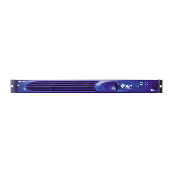
Cobalt LX50
User Manuals: Sun Microsystems Cobalt LX50 Server
Manuals and User Guides for Sun Microsystems Cobalt LX50 Server. We have
1
Sun Microsystems Cobalt LX50 Server manual available for free PDF download: User Manual
Sun Microsystems Cobalt LX50 User Manual (138 pages)
Brand:
Sun Microsystems
| Category:
Server
| Size: 2 MB
Table of Contents
Preface
3
Who Should Use this Book
3
Conventions Used in this Manual
3
Related Documentation
4
Ordering Sun Documents
4
Accessing Sun Documentation Online
4
Shell Prompts in Command Examples
4
Notice
4
Table of Contents
5
Figures
11
Introducing the Sun Cobalt LX50 Server
15
Overview of the Sun Cobalt™ LX50 Server
15
The Sun Cobalt LX50 Server
15
Replaceable Components
15
Chapter 1
17
Contents of the Ship Kit
17
Replaceable Components
18
Optional RJ-45 to DB9 Serial Adapter Kit
19
DCD Modem Cable
19
DSR Peripherals Cable
19
Front EMP Cable
19
Preinstalled Software
20
Installation Quickstart
21
Installation Quickstart Procedure
21
Installing the Server in a Rack
23
Decide Where to Configure the Sun Cobalt LX50 Server
23
Chapter 2
24
Precautions
24
Introduction
25
Installing the Server Using the Bracket Kit
26
Kit Contents
26
Required Tools
26
Attach Brackets to Chassis
27
Mounting in a Four-Post Rack System
27
Remove the Chassis Handles
27
Removing a Handle from the Chassis
27
Attach Disks to Chassis
28
Attaching a Chassis Disk to the Chassis
28
Installing a Chassis Bracket in the Front-Mount Position
28
Attach Brackets to Rear Posts
29
Install Chassis in Rack
30
Installing the Chassis in the Rear Brackets
30
Attaching a Chassis Handle to a Front Post
32
Install Chassis Handles
32
Attach Brackets to Chassis
33
Installing a Chassis Bracket in the MID-Mount Position
33
MID-Mounting in a Two-Post Rack System
33
Attach L Brackets to Center Posts
34
Attaching an L Bracket to a Center Post
34
Install Chassis in Rack
35
L Brackets Inserted into Chassis Mounting Brackets (Rear View)
35
Installing the Chassis in the Rack
36
Front-Mount-Only in a Two-Post Rack System
37
Remove the Chassis Handles
37
Removing a Handle from the Chassis
37
Attach Brackets to Chassis
38
Installing a Chassis Bracket in the Front-Mount Position
38
Attach L Brackets to Center Posts
39
Attaching an L Bracket to a Center Post
39
Install Chassis in Rack
40
L Brackets Inserted into Chassis Mounting Brackets (Rear View)
40
Installing the Chassis in the Rack
41
Attaching a Chassis Handle to a Center Post
42
Install Chassis Handles
42
Installing the Server Using the Slide Rail Kit (Optional)
43
Kit Contents
43
Remove the Inside Rails
43
Required Tools
43
Attach Inside Rails to Chassis
44
Attach a Rail Assembly to a Front Bracket
45
Attach Rail Brackets to Posts
45
Attaching a Rail Bracket to a Rack Post
45
Attach a Rail Assembly to a Rear Bracket
46
Attaching a Rail Assembly to a Front Bracket
46
Attaching a Rail Assembly to a Rear Bracket
47
Install the Chassis on the Rails
47
Connecting the Cables
49
Front Panel Connectors
49
Front RJ-45 Serial 2 Connector
49
Front RJ-45 Serial 2 Port Adapter Pinout
50
Rear Panel
51
Rear Panel Connectors
51
RJ-45 NIC 1 and NIC 2 Connectors
51
USB Connectors
51
AC Power Connector
52
Rear Panel RJ-45 Serial 2 Connector
52
J6A2 Jumper Block Configured for DCD Signal (Pin 7 Connected to DCD)
53
PS/2 Keyboard/Mouse Connector
54
SCSI Connector
54
USB 3 and USB 4 Connectors
54
Video Connector
54
Controls and Indicators
55
Front Panel Leds and Pushbuttons
55
Leds
56
Pushbuttons
56
Rear Panel Leds
57
Powering on and Configuring the Server
59
Setting the Jumper Positions
59
Powering on
59
Clearing CMOS
60
Booting up
60
Boot Options
60
Chapter 4
60
Powering on
60
BIOS Setup Utility <F2
61
BIOS Setup Utility Main Screen
61
BIOS Setup Utility Exit Screen
62
Default Boot Sequence
62
Choose Boot Device <ESC
63
Network <F12
63
Service Partition <F4
63
Initialization Sequence
64
Linux Loader (LILO) Menu Options
64
Configuring an External Serial Console
65
Configuring an External Serial Console
65
Service Partition Menu
67
Using the Service Partition Menu
67
Create Diskettes
68
Create Diskettes Submenu
68
System Utilities
69
System Utilities Submenu
69
Run System Setup Utility
70
SSU Main Window
70
Run System Diagnostic Test
73
Sample RESULT.LOG
78
Sample RESULT.LOG (Continued)
79
Firmware Update
83
Reboot System
83
Reboot to Service Partition
83
Run Baseboard Management Controller (BMC Firmware Update
83
Run BIOS Update (Reboot Required)2
83
Run Field Replaceable Unit/System Data Record
83
Run HSC Firmware Update
83
Hardware Mechanisms
84
Restarting and Shutting down
84
Software Mechanisms
84
Maintaining the Server
85
Chapter 5
86
Tools and Supplies Needed
86
Determining a Faulty Component
86
Safety: before You Remove the Cover
86
Removing and Replacing the Cover
87
Customer Replaceable Unit (CRU) Procedures
88
Front Bezel
88
Floppy/CD-ROM Combo Module
89
Memory
90
Power Supply Unit
91
Hard Disk Drives
92
Air Baffle
94
Installation
94
Removal
94
Fan Module
95
PCI Cards
97
Battery
98
Field Replaceable Unit (FRU) Procedures
99
Replacing a CPU and Heatsink
99
Safety Cautions
99
Raising the Locking Lever
100
Raising the Locking Bar
101
Inserting the Processor and Lowering the Locking Bar
102
Installing the Heat Sink and Clip
103
Closing the Locking Lever
104
Installing a New CPU and Heatsink
105
Safety Cautions
105
Inserting the Processor and Lowering the Locking Bar
106
Closing the Locking Lever
107
Installing the Heat Sink and Clip
107
Server Main Board
108
Cable Kit
111
Removal
111
Installation
112
System FRU
113
Troubleshooting the Server
115
Chapter 6
116
Diagnosing System Errors
116
Beep Codes
116
Leds
116
Platform Confidence Test (PCT)
116
POST Screen Messages
116
System Setup Utility (SSU)
116
System Utilities
116
Status Leds
117
Front-Panel System Status LED
117
Location of Front-Panel System Status LED
117
System Status LED States
117
Other Leds
118
Power Supply Status LED States
118
Rear Panel Power Supply Status LED
118
Server Main Board Fault Leds
119
System ID Leds
120
Location of Front-Panel ID LED
120
Power-On Self Test (POST)
121
POST Screen Messages
121
POST Beep Codes
124
BIOS Recovery Beep Codes
126
POST LED Indicators
126
Contacting Technical Support
131
Specifications
133
Cpu
133
Dual Intel Pentium III Processors
133
Chipset
133
Serverworks Serverset* III HE-SL Chipset
133
I/O Subsystems
134
Three Separate and Independent PCI Buses
134
Segment A: 32 Bit, 33 Mhz, 5 V (P32-A) with Four Embedded Devices
134
Segment B: 64 Bit, 66 Mhz, 3.3 V, (P64-B) Supporting the Following Configuration
134
Segment C: 64 Bit, 66/33 Mhz, 3.3 V (P64-C) Supporting the Following Device
134
LPC: (Low Pin Count) Bus Segment with Two Embedded Devices
134
System I/O Port Summary
134
Video Capabilities
135
Video Modes
135
SCSI Capabilities
136
Server Management Features
136
Power Supply
137
Dimensions
137
Weight
137
Mounting Options
137
Environmental
138
Ambient Temperature
138
Relative Humidity
138
Vibration
138
Shock
138
Acoustics
138
Advertisement
Advertisement
Related Products
Sun Microsystems StorageTek L40
Sun Microsystems L7ZF
Sun Microsystems StorEdge L7
Sun Microsystems storedge L25
Sun Microsystems storedge L100
Sun Microsystems StorEdge L1800
Sun Microsystems StorEdge L8
Sun Microsystems StorEdge L280
Sun Microsystems StorEdge L1000
Sun Microsystems StorEdge L400
Sun Microsystems Categories
Server
Storage
Desktop
Computer Hardware
Adapter
More Sun Microsystems Manuals
Login
Sign In
OR
Sign in with Facebook
Sign in with Google
Upload manual
Upload from disk
Upload from URL