
Related Manuals for Blankom VMA 191


Summary of Contents for Blankom VMA 191
- Page 1 Professional Headend Solutions Device manual Audio/ Video Modulator A/V → ATV (AM) VMA 191 Part N : 9228.8x/ .9x...
-
Page 2: Table Of Contents
VMA 191 Audio/ Video Modulator A/V → ATV (AM) Part N : 9228.8x/ .9x LINE Contents 1. Safety and operating instructions ......................3 2. Device variants ............................3 3. General ..............................3 4. Functional description ..........................3 5. Explanation of the operating elements ....................4 5.1 Front view ............................ -
Page 3: Safety And Operating Instructions
After each programming of the level and/or frequency values an automatic measurement of the reference level takes place. The monitoring of the input signal is done at the output of the VMA 191. If the IF loop is activated the IF input is weighted. -
Page 4: Explanation Of The Operating Elements
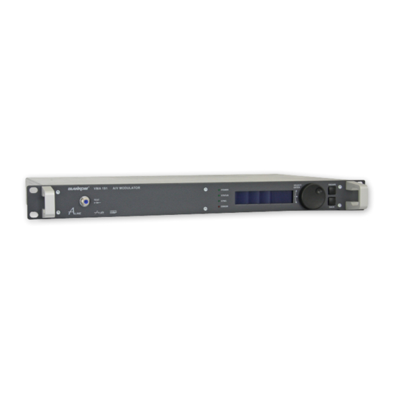
VMA 191 Audio/ Video Modulator A/V → ATV (AM) Part N : 9228.8x/ .9x LINE 5. Explanation of the operating elements 5.1 Front view POWER - LED STATUS - LED SYNC. - LED ERROR - LED Tuning wheel Test (-30 dB) -
Page 5: Rear View
VMA 191 Audio/ Video Modulator A/V → ATV (AM) Part N : 9228.8x/ .9x LINE 5.4 Rear view FUSE OF DEVICE ALARM LAN / WAN POWER FACTORY SET RF-OUT AUDIO-IN VIDEO-IN IF-IN IF-OUT 5.5 9-pin D-SUB connector configuration (alarm contact) -
Page 6: Factory Settings
IP address of the VMA 191 (subnet mask: 255.255.255.0, IP address: 192.168.2.XXX). Don`t be use the same combination lock for XXX like the IP address of the VMA 191. The IP address of the VMA 19x is entered onto the browser interface. -
Page 7: Device Status
VMA 191 Audio/ Video Modulator A/V → ATV (AM) Part N : 9228.8x/ .9x LINE 6.2 Device status Choose language german, english Device settings Identifier e.g. programme name acc. adjustments in 6.3 Frequency acc. adjustments in 6.3 Level acc. adjustments in 6.3 Level monitoring acc. -
Page 8: Extended Settings
VMA 191 Audio/ Video Modulator A/V → ATV (AM) Part N : 9228.8x/ .9x LINE 6.4 Extended settings Choose language german, english Input Audio impedance selection: 600/ 12000 Ohm Audio signal selection: balanced/ unbalanced Audio level adjustment range: -6 ... 9 dBu... -
Page 9: Ip Network
VMA 191 Audio/ Video Modulator A/V → ATV (AM) Part N : 9228.8x/ .9x LINE 6.6 IP network Selecting this menu at first the administrator log-in window will be open automatically. Following successful log-in the network and log-in settings can be changed. -
Page 10: Snmp Management
Choose language german/english The complete MIB for an VMA 191 can be downloaded like descriped un- der “Instructions“ on this web-site and clicking the “MIB Download”-link. With the aid of an MIB browser, the relevant MIB can be decided upon and taken over to control the device via a SNMP manager and/or an network manager capable of SNMPv2c. -
Page 11: Menu Structure Of Display Handling
VMA 191 Audio/ Video Modulator A/V → ATV (AM) Part N : 9228.8x/ .9x LINE 8. Menu structure of display handling The following settings are the default settings. After a reset by pressig of „FACTORY SET“ on the rear side of the device all settings stored in the EEPROM will be deleted and replaced by these defaults and the device will go back to these settings (see chapter 5.7). -
Page 12: Block Diagram
VMA 191 Audio/ Video Modulator A/V → ATV (AM) Part N : 9228.8x/ .9x LINE 9. Block diagram Vestigial sideband Video/ IF modu- Audio- Filter- lator Processing bank 2x FM Audio/ modulator Video + 12 V Test out- Controller + —... -
Page 13: Glossary
VMA 191 Audio/ Video Modulator A/V → ATV (AM) Part N : 9228.8x/ .9x LINE 11. Glossary Automatic Gain Control Amplitude modulation Analogue Television Audio/Video Bandwidth Carrier to Noise ratio Electromagnetic Compatibility Frequency modulation HTML Hypertext Markup Language HTTP Hypertext Transfer Protocol... - Page 14 Declaration of Conformity The Manufacturer BLANKOM Antennentechnik GmbH ∙ Hermann-Petersilge-Str. 1 ∙ 07422 Bad Blankenburg ∙ Germany herewith declares the conformity of the product group Audio/ Video Modulator Product name: VMA 191 Type: 9228.8x, 9228.9x Product number: according to the following regulations...
Need help?
Do you have a question about the VMA 191 and is the answer not in the manual?
Questions and answers