Page 1
No. 0403E DZ-MV580A DZ-MV580A(K) SERVICE MANUAL DZ-MV550A DZ-MV550A(K) PWB part numbers added 07/16/04 MultiMediaCard DO NOT RESELL OR DIVERT IMPROPERLY SPECIFICATIONS AND PARTS ARE SUBJECT TO CHANGE FOR IMPROVEMENT 
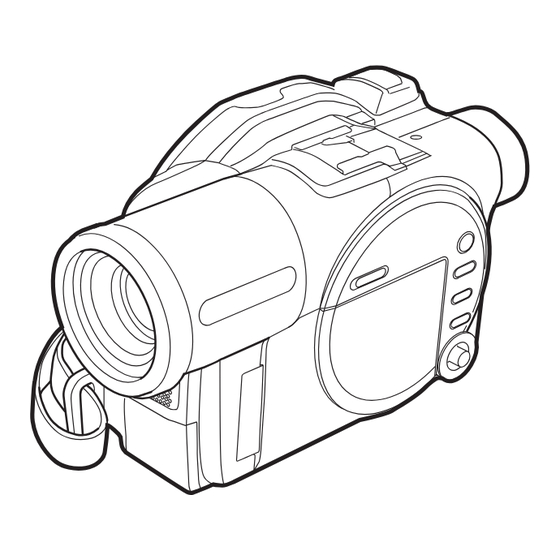
DVD VIDEO CAMERA/RECORDER March 2004 Digital Media Division,Tokai Version 0403E.01...
Hand Strap ........5-10 Troubleshooting ........4-22 (12) SHE-H/SHE Circuit Board and Accessory 4-5-1 Message displayed by Shoe in DZ-MV580A ......5-11 self-diagnosis function ......4-22 (13) SHE Circuit Board in DZ-MV550A ..5-11 4-5-2 Error codes stored in flash memory ..4-24 (14) Accessory Shoe in DZ-MV550A ....
Page 3
7-1-2 R Block ..........7-2 Reference Data ........6-2 7-1-3 LCD Unit ..........7-3 6-1-2 Power Supply and Materials for Creating 7-1-4 DZ-MV580A Camera Block ....7-3 Reference Data ........6-3 7-1-5 DZ-MV550A Camera Block ....7-3 6-1-3 Connections when Creating 7-2 Replacement Parts List ......
The use of a substitute replacement component which does not have the same safety characteristics as the HITACHI recommended replacement one, shown in the parts list in this Service Manual, may create shock, fire, or other hazards. Product safety is continuously under review and new instructions are issued from time to time.
Safety Precaution for Repair > Electrostatic Protection Measures / Cautions When Handling DVD Drive 1-2 Electrostatic Protection Measures Semiconductor components can be damaged by static electricity charged on clothes, human body, etc. Take great care when handling components to avoid electrostatic damage, and perform servicing in an environment where grounding is complete.
Safety Precaution for Repair > Lead-Free Solder 1-4 Lead-Free Solder The printed circuit board that uses lead-free solder is adopted. To protect the global environment, use the recommended lead-free solder also during servicing. Read and observe the following before soldering: Caution ALWAYS wear protective goggles during soldering so that no solder smoke or scattered solder enters the eye.
Page 8
Safety Precaution for Repair > Lead-Free Solder (5) Cautions when using lead based solder It is recommended that you use lead-free solder when servicing, but it is also possible to service using lead based solder. However, if lead based solder is used for servicing, take care with the following: 1) Before using lead based solder, remove the lead-free solder completely from the point to be soldered.
Safety Precaution for Repair > Notes When Using Service Manual 1-5 Notes When Using Service Manual (1) Value units used in parts list Certain symbols are indicated as shown below for value units of resistors, capacitors and coils in parts list. When you read them, note the following regular indications: Parts Indication in list Regular indication...
Page 10
Safety Precaution for Repair > Notes When Using Service Manual (4) Table for indexing locations of parts This table shows locations of each part on circuit board diagrams. The locations are indicated using the guide scales on the external lines of diagrams. 1) One diagram indicated for each board 2) Two diagrams indicated for each board Symbol...
The DZ-MV580A DVD video camera/recorder has been made more compact than the previous DZ- MV380A; the DZ-MV550A has been made compact than the DZ-MV350A. The DZ-MV580A has a CCD image sensor with a total of 1,020,000 pixels and a high-performance optical 10-power zoom.
The Quick mode displays only the fundamental menu items; a brief explanation of the selected item is displayed across the bottom of screen. Fig. 2-2-1 2-3 Specifications Item Specifications CCD Image Sensor DZ-MV580A 1/3.8-inch interlaced DZ-MV550A 1/6-inch interlaced Total number of DZ-MV580A Approx. 1,020,000 pixels DZ-MV550A Approx.
Page 13
DVD-R disc Video: Conforming to DVD video format Audio: MPEG Audio layer 2 or LPCM Card Photo: Conforming to JPEG (DZ-MV580A: 1280 × 960 pixels, DZ-MV550A: 640 × 480 pixels) format [External input: 640 × 480 pixels] Audio playback format...
Page 14
PC connection cable Single-sided 8cm DVD-RAM disc (in round DVD holder) *1: The DZ-MV580A/MV550A records audio on DVD-R disc using the MPEG Audio layer 2 format in FINE or STD mode, and using the LPCM format in LPCM mode. The MPEG Audio layer 2 format is an option of DVD video standard. Record a DVD-R disc in LPCM mode to play it back on a DVD player that does not comply with this option standard.
Approx. 64KB ECO: Approx. 32KB 2-5 Compatibility of Recorded Discs Discs recorded or edited on DZ-MV580A/MV550A can also be recorded, edited and played back on other DVD video camera/recorders, except for those for which disc-protect has been set. (*1) Discs recorded or edited on other DVD video camera/recorders can also be recorded, edited and...
DZ-MV580A are different, the 2.5" type liquid crystal display (inside) method of operating both models is identical. QUICK MODE switch DZ-MV580A illustrations are used in this To switch the menu display on screen between manual. Advanced mode and Quick mode.
Page 19
General Description > Names of Parts 27 FULL AUTO button 29 30 To switch the DVD video camera/recorder to full automatic. 28 FOCUS button To switch between manual focus and autofocus. 29 EXPOSURE button Press this button to adjust the exposure. 30 BLC (backlight compensation) button Press this button when subject is being lighted from rear.
General Description > List of Abbreviations and Terms for DVD Video Camera/Recorders 2-7 List of Abbreviations and Terms for DVD Video Camera/Recorders Index Abbreviation/Term Explanation See Dolby AC3. CPRM Content Protection for Recordable Media: Copyright protection function that is suitable for online distribution of music. Design rule for Camera File system standard: This camera file system standard, established by JEIDA (now merged to JEITA).
Page 21
General Description > List of Abbreviations and Terms for DVD Video Camera/Recorders Index Abbreviation/Term Explanation MPEG Motion Picture Experts Group: Standard related to compression of digital video and audio. MPEG2 is a higher standard of MPEG and is applied to video (movie) requiring higher quality.
3-1 Description of Structure (1) Configuration and locations of circuit boards The configuration of circuit boards in DZ-MV580A/MV550A and their locations are very similar to those in the base models DZ-MV380A/MV350A, except for whether the FAF circuit board is provided or not.
(2) Differences in structure between DZ-MV580A and DZ-MV550A There are two major differences in structure between DZ-MV580A and DZ-MV550A: 1) Accessory shoe The accessory shoe on DZ-MV580A has a power/control terminal, but the accessory shoe on DZ- MV550A doesn’t. 2) Lens unit The lens unit in DZ-MV550A includes the cushion, crystal filter, CCD image sensor and SEN-H circuit board, which are discrete from the lens unit in DZ-MV580A.
Troubleshooting 4-1 Procedure for Troubleshooting Perform troubleshooting in the order shown in Fig. 4-1-1. Updating No improvement No improvement unneeded No message or Check firmware Trouble Check Check Problem guide System reset error code version Diagnosis troubleshooting phenomenon (section 4-3) (section 4-2) appears (section 4-6-1)
4-2 System Resetting/Resetting Camera Functions The DZ-MV580A/MV550A has two types of reset function: “System reset” and “Resetting camera functions”. The reset operation will return the various settings to the defaults when the DZ-MV580A/MV550A was shipped form factory. Information: If a defect occurs in product, take note of settings, and then execute system reset first: The defect may disappear.
Page 26
FINE FINE, NORM, ECO Displayed only in the card photo mode Input Source CAMERA CAMERA, LINE, S LINE S LINE is displayed only on DZ-MV580A PHOTO Input Field Frame, Field Self Timer On, Off OSD Output On, Off Displayed only when “Input Source:...
1) Connect the battery or AC adapter/charger to power the DZ-MV580A/MV550A. 2) Set the power switch to “VIDEO” and place the DZ-MV580A/MV550A in the recording pause status; loading disc is not necessary at this time. For the following steps, operate DZ-MV580A/ MV550A while viewing the LCD monitor or viewfinder.
Execute system reset (disconnect the battery or AC adapter/charger, and then use a fine tipped pen, etc. to hold down the RESET button for several seconds). Then connect a battery or AC adapter/charger and make sure the DZ-MV580A/ MV550A accepts operation.
Page 29
AV device directly. Are you attempting to record image from video game or PC? Depending on video game or PC, image cannot be recorded on DZ-MV580A/ MV550A. Power switch does not Is the LOCK switch beside the power switch set to the left? Switch it to the right change to PHOTO (disc).
Page 30
Has scene been edited on a device other than DZ-MV580A/MV550A? If a scene that was recorded on DZ-MV580A/MV550A is edited on a device other than DZ-MV580A/MV550A, playback may not be possible on DZ-MV580A/ MV550A. No playback image appears Is TV input selector set correctly? on TV screen.
Page 31
Turn the PC and DZ-MV580A/MV550A off, and try again. run on PC. DISC EJECT button does The DISC EJECT button is invalid while DZ-MV580A/MV550A is connected to not work when DZ-MV580A/ MV550A is connected to PC. Start Windows Explorer, right-click the drive icon corresponding to DZ-MV580A/ MV550A, and then click "Eject".
Page 32
DVD-RAM disc in DZ- MV580A/MV550A to be read by the PC. Video is not recognized by Is the power switch of DZ-MV580A/MV550A set to "VIDEO" or “PHOTO (disc)”? software in PC. Set it to "VIDEO" or “PHOTO (disc).
Page 33
Reconnect power supply, set the power switch to "VIDEO", and then remove the disc after the sound showing the disc lock has been released is heard. If the disc still cannot be removed, the DZ-MV580A/MV550A is faulty: Refer to "4-8 Procedure for Removing Disc from Faulty DZ-MV580A/MV550A".
Page 34
Is round DVD holder inserted in the proper orientation? Remove the round DVD holder, make sure of the orientation, and then reinsert Is DZ-MV580A/MV550A turned on? Connect the AC adapter/charger or full charged battery and set the power switch to a position other than “POWER OFF”.
DVD-R disc. *1: the DVD video recording format defines the maximum number of entry points as 999: Since one entry point is allocated to one scene, the maximum number of scenes recordable on disc with DZ-MV580A/ MV550A is 999. *2: If recording is continued without editing, one scene will comprise one cell for each entry point.
Page 36
Troubleshooting > Messages and Troubleshooting Cause/condition for Message Troubleshooting message to appear Cannot replace thumbnail Appears when a photo thumbnail was Select a video to change the on PHOTO scenes. selected for change in scene editing thumbnail. menu: The specifications stipulate that the thumbnail of photo cannot be changed.
Page 37
If the disc is removed while it is being recognized, the repair function of video file will be invalid. b) If the timing when power is turned off is inappropriate, normal repair may be impossible. c) If the disc has data that was recorded on a device other than DZ-MV580A/MV550A, normal repair may be impossible.
Page 38
[Refer to *3 page 4-14] repaired. Also appears when condensation occurs Do not execute repair, but set the on lens or drive of DZ-MV580A/MV550A. power switch to “POWER OFF” with Condensation will occur when the DZ- the disc loaded, and then leave the...
Page 39
“POWER OFF” with the disc loaded; then reconnect the AC adapter/charger and set the power switch to “VIDEO” or “PHOTO (disc)”. (The DZ-MV580A/ MV550A will automatically repair the video file.) Disc full. Appears if the recording capacity of disc Delete unnecessary scenes, or replace Cannot execute.
Page 40
××××.) recording. *4: The purpose of formatting DVD-R disc on DZ-MV580A/MV550A is to write to disc a program exclusively for camera recording that is necessary to record images shot by camera in real time (increasing the response from disc). When recording images that were edited using PC on DVD-R disc via the PC connection terminal, do not format the disc: The program used exclusively for camera recording will disable normal recording.
Page 41
ERROR ×××× Appears if the self-diagnosis function in Take note of the 4-digit alpha- (4-digit alpha-numerals DZ-MV580A/MV550A detects a serious numerals in ××××, and refer to “4-5 showing the code of trouble problem during recording, or when the Self-Diagnosis Function and will appear in ××××.)
Page 42
If the message appears even when a disc Set the power switch to “POWER is loaded, condensation might have OFF” with the disc loaded, and then occurred on lens or drive of DZ-MV580A/ leave the DZ-MV580A/MV550A in a MV550A. dry place until condensation disappears (usually 1-2 hours).
Page 43
This disc cannot be used. Appears when a type of disc that cannot Check the type of disc and insert a Please replace disc. be used on DZ-MV580A/MV550A was disc usable on DZ-MV580A/MV550A. loaded. This disc is recorded by the...
Page 44
DVD-R disc can “POWER OFF” with the disc loaded, be finalized only when the AC adapter/ remove the battery, and then connect charger powers the DZ-MV580A/ the AC adapter/charger: Finalize the MV550A. disc again. Use AC adapter/charger.
The information included in this section is exclusively for service personnel. Do not disclose it to persons other than service engineers. The DZ-MV580A/MV550A is equipped with a self-diagnosis function: If it detects a problem when power is turned on or during operation, it will display a message, replace the content of problem with an error code (4-digit alphanumeric characters), and then store it in flash memory.
Page 46
Troubleshooting > Self-Diagnosis Function and Troubleshooting (2) Messages for serious problems These messages appear when solving the problem detected when power is turned on or during operation is not likely by turning power on again or reloading the disc: Error codes Error has occurred.
Troubleshooting > Self-Diagnosis Function and Troubleshooting 4-5-2 Error codes stored in flash memory (1) Displaying error codes and clearing them Display method E r r o r c o d e s 1) Use the battery or AC adapter/charger to power DZ- MV580A/MV550A, and then set the power switch to “VIDEO”.
3) Check to see whether or not condensation has occurred. If condensation has occurred, set the power switch to “POWER OFF” with the disc loaded, and then leave the DZ-MV580A/MV550A in a dry place for 1-2 hours. 4) Replace the disc.
Page 49
3126 Writing data file to disc failed. switch to “VIDEO” or “PHOTO” (disc). 3133 Take care not to subject DZ-MV580A/MV550A to 7601 It takes much more time than impact or vibrations at this time. necessary to process start or end of 2) Set the power switch to “POWER OFF”, remove the...
Troubleshooting > Checking Versions of Firmware and Updating 4-6 Checking Versions of Firmware and Updating The DZ-MV580A/MV550A stores the 4 types of firmware shown in Table 4-6-1 in flash memory. These firmware programs will be updated whenever necessary to improve the performance of DZ- MV580A/MV550A.
Drive (Core): xxxx.xx.xx. REV RETURN Fig. 4-6-1 4-6-2 Updating firmware (1) Purpose If you receive information from the factory that updating firmware is needed, you should do it to improve the performance, functions and operability of DZ-MV580A/ MV550A. 4 - 28...
Page 52
2) Set the power switch to “POWER OFF”, and then use the AC adapter/charger to power the DZ- MV580A/MV550A. A battery cannot be used because it may interrupt power of DZ-MV580A/ MV550A during work. 3) Insert the disc/card for updating firmware.
1) Search for the defective symptom. If there are multiple check points or multiple details of check for one symptom, check the items from the top down. 2) Set the DZ-MV580A/MV550A to a service position that matches the symptom. There are four service positions (A)-(D) for DZ-MV580A/MV550A. Set to the appropriate service position, referring to “Disassembly/reassembly to enable service position”.
Troubleshooting > Trouble Diagnosis Table 4-7-1 Trouble Diagnosis Table Service Troubleshooting due to Symptom Check points Detail of check position check results No power F0501 [MAN-B] Is fuse blown? Yes: Replace MAN-H/ F0502 [MAN-B] MAN circuit board. F0503 [MAN-B] F0504 [MAN-B] TL0504 [MAN-B] Is the voltage approx.
Page 55
TL2090 [MAN-A] TL2091 [MAN-A] TL2095 [MAN-A] TL2082 [MAN-A] Can video signal (CCD-OUT) Yes: Replace MAN-H/ be confirmed? MAN circuit board. With DZ-MV580A, replace IC1001. With DZ-MV550A, replace lens unit. No image from AV ----- ----- Does image appear on LCD...
Page 56
Troubleshooting > Trouble Diagnosis Service Troubleshooting due to Symptom Check points Detail of check position check results No sound from TL1534 [MAN-B] Can audio signal (SP_OUT+, Yes: Replace disc cover. speaker TL1535 [MAN-B] SP_OUT-) be confirmed? IC6103 and its peripheral circuits are faulty.
Page 57
Troubleshooting > Trouble Diagnosis Service Troubleshooting due to Symptom Check points Detail of check position check results Even when a disc ----- ----- ---------- Replace disc drive unit. not protected is inserted, message "Write protected. Check disc" appears. Even when a ----- ----- ----------...
Page 58
4-7-2 Disassembly/reassembly to enable service position Prohibition Be sure to disconnect the AC adapter/charger or battery from the DZ-MV580A/MV550A. The DZ-MV580A/MV550A has a built-in laser emitter block. Never look into it: If Laser beam strikes your eye, it could cause serious vision damage. Information: Numbers in diagrams are step numbers for setting procedure.
Page 59
Troubleshooting > Trouble Diagnosis 2) Attach the MAN-H/MAN circuit board independently to the frame, and connect the DRF-H/DRF circuit board to it. 3) Assemble the USB holder, USB-H/USB circuit board and rear cover. 4) Assemble the disc cover so that hinge of side case-R fits into point at the top of inside of disc cover.
Page 60
Troubleshooting > Trouble Diagnosis (2) Setting to service position (B) Service position (B) is mainly used for trouble LEAD WIRES diagnosis of the video and audio signal systems. Perform trouble diagnosis using the check points on MAN-H/MAN and AEL-H/AEL circuit MAN-H/MAN CIRCUIT Remove the MAN-H/MAN and AEL-H/AEL...
Page 61
Troubleshooting > Trouble Diagnosis 2) Assemble the MAN-H/MAN and AEL-H/AEL circuit boards on the frame. [G] M1.7x3 (Gold) 3) Assemble the SEH-H/SEH circuit board and [H] M1.6x2 (Gold) accessory shoe. (See Fig. 4-7-7) 3) [H] 4) Assemble the USB holder, USB-H/USB circuit board, rear cover and EVF unit.(See Fig.
Page 62
Troubleshooting > Trouble Diagnosis (3) Setting to service position (C) Service position (C) is mainly used for trouble LEAD AEL-H/AEL diagnosis of the system of operation buttons on WIRES CIRCUIT L-BLOCK BOARD side case-L. Perform trouble diagnosis using the check points on MAN-H/MAN and AEL-H/AEL circuit boards.
Page 63
Troubleshooting > Trouble Diagnosis (4) Setting to service position (D) Service position (D) is used for trouble diagnosis of the LCD monitor. CIRCUIT BOARD Remove the LCD case-U, MR circuit board and fulcrum block in advance, referring to “5. Disassembly and Reassembly”. 1) Connect the flat cable of fulcrum block to LCD and AEL-H/AEL circuit boards.
4-8 Procedure for Removing Disc from Faulty DZ-MV580A/ MV550A 4-8-1 Item to be checked Connect the AC adapter/charger or charged battery pack (power supply), making sure the ACCESS indicator turns off, and then press the DISC EJECT button again. Note: Even with normal product, the disc cannot be removed while the ACCESS indicator is lit or blinking.
2) Do not turn power off or remove the disc during initialization: Such an interruption will make the disc unusable. 1) Use the AC adapter/charger to power DZ-MV580A/ MV550A, and set the power switch to “VIDEO” or Use soft cloth to clean from inner to outer “PHOTO”.
DZ-MV580A/MV550A incorporates high-voltage circuits and a laser emitter block. Note: 1) Always connect the Skylark connection jig before connecting the DC power cord to DZ-MV580A/ MV550A: Connecting the Skylark connection jig after powering the DZ-MV580A/MV550A could cause a fault.
Page 67
Troubleshooting > Special Functions REMOVE THE ADJUSTMENT COVER [Refer to "(1) Adjustment cover" in "5-3 Disassembly".] DC POWER CORD To AC OUTLET SKYLARK CONNECTION POWER CABLE POWER SUPPLY (No. TP14161) (5V/1A) DZ-ACS1 (PIN 16) RS-232C CABLE DSP-R JIG (No. 7099448) (PIN 20) (PIN 18) Fig.
Page 68
Information: ADJUST MENU If it is not possible to back up the data in EEPROM to be DATA INITIALIZE replaced because the DZ-MV580A/MV550A is not turned VIDEO LEVEL BURST LEVEL on, etc., replace the MAN-H/MAN circuit board, and then SAMPLING PULSE refer to “6-4-1 Initial Data Write”.
Page 69
Troubleshooting > Special Functions ADJUST MENU screen (4) Write method MANUAL ADJUSTMENT PROGRAM for SERVICE STATION ×××× MODEL NAME: Restrictions: ADJUST MENU Never write data of any other product. DATA INITIALIZE VIDEO LEVEL The EEPROM data includes adjustment values, etc. that BURST LEVEL are peculiar to that product: It is different for each SAMPLING PULSE...
After the above check, be sure to disconnect the AC adapter/charger or battery from the DZ- MV580A/MV550A. The DZ-MV580A/MV550A has a built-in laser emitter block. Never look into it: If Laser beam strikes your eye, it could cause serious vision damage.
Disassembly and Reassembly > Disassembly 5-3 Disassembly Information: Numbers in disassembly procedure diagrams are step numbers for disassembling order, and letters in brackets [ ] show the types of screw. Letters in brackets ( ) show the name of parts. (a) Adjustment cover (1) Adjustment Cover (b) LCD monitor...
Disassembly and Reassembly > Disassembly (3) SAF-H/SAF Circuit Board and L Block 1) Open the LCD monitor (c). 2) Remove three screws [A], two screws [N] and three screws [C]. 3) Close the LCD monitor and open the L block (b) from the rear in the direction of the arrow: Be careful not to damage the SAF-H/SAF circuit board (a) or flat cable between L block and R block (d).
Disassembly and Reassembly > Disassembly (a) Front block (4) Front Block and R Block (b) R block 1) Open the jack cover (c), and then remove one (c) Jack cover screw [N]. (d) FRT-H/FRT circuit board (e) AEL-H/AEL circuit board 2) Remove one screw [N].
Disassembly and Reassembly > Disassembly (7) SWL3-H/SWL3 Circuit Board 1) Unplug the connector. Be sure to hold the connector using tweezers, etc. when unplugging it. Pulling the cable when unplugging the connector could cause wire disconnection. 2) Remove one screw [D]. Procedure and caution for reassembly 1) Insert the switch knob (b) on SWL3-H/SWL3 circuit board between the knobs (c) of L cover.
Disassembly and Reassembly > Disassembly (8) Side Case L, LCD Unit, and SWL2 Circuit Board 1) Unplug the connector. Be sure to hold the connector using tweezers, etc. when unplugging it. Pulling the cable when unplugging the connector could cause wire disconnection. 2) Remove five screws [D].
Disassembly and Reassembly > Disassembly (9) LCD Case-U, MR Circuit Board, and Fulcrum Block LCD Case-U (a) 1) Insert an awl (e), etc. into the screw hole, and turn the screw-hole bracket of fulcrum block 90° in the direction of the arrow. At this time, make no mistake with the turning direction: Turning in the wrong direction will deform fulcrum cover U.
Disassembly and Reassembly > Disassembly (10) Disc Cover 1) Remove the space sheet (b) that covers the opening for operating lock arm. 2) Use a fine-tipped flat-bladed screwdriver to move the lock arm (d) in the direction of the arrow to open the disc cover (a).
Disassembly and Reassembly > Disassembly (11) USB Holder, USB-H/USB Circuit Board, Rear Cover, EVF Unit, and Hand Strap Note: Before replacing the EVF unit, always perform “(1) BL DET Check” in “6-4-11 EVF”. USB Holder (a) and USB-H/USB Circuit Board (b) 1) Remove one screw [F].
(a) Camera block (b) Frame (c) hook of camera frame (d) square hole in frame 1) [F] 1) [F] DZ-MV550A DZ-MV580A [F] M1.6x2.5 (Black) 1) [F] 1) [F] Fig. 5-3-18 (17) Link Bracket (a) Link bracket 1) Remove two screws [H], and then remove the link bracket (a).
Disassembly and Reassembly > Disassembly (18) Drive Block and Side Case-R 1) Remove five screws [F] and two screws [A], and then remove the drive block (a) from the side case-R (b). Note: Take great care when handling the drive block: The drive block contains the disc drive unit, which is a precision component.
Disassembly and Reassembly > Disassembly (19) Loader, DRF-H/DRF Circuit Board, Disc Drive Unit, Lock Unit, and Frame Loader (a) 1) Remove two screws [L], and then remove the loader. DRF-H/DRF Circuit Board (b) and Disc Drive Unit (c) 2) Remove three screws [K]. 3) Disconnect the one flat cable.
Disassembly and Reassembly > Disassembly (20) Fulcrum Cover-U, Fulcrum Cover-B (a) Fulcrum cover-U and Fulcrum Unit (b) Fulcrum cover-B 1) Remove two screws [P], and then remove the (c) Fulcrum unit fulcrum cover-U (a) and fulcrum cover-B (b) from the fulcrum unit (c). 1) [P] [P] M1.6x3 (Black) Fig.
Disassembly and Reassembly > Disassembly (23) GYR Circuit Board, Lens Frame, and Lens Unit in DZ-MV550A (a) GYR circuit board (b) Lens frame Information: (c) Lens unit 1) [D] The DZ-MV550A lens unit is set as a service component: It includes the parts equivalent to cushion rubber, crystal filter, CCD image sensor and SEN-H circuit board of DZ- MV580A.
3) Refer to the following table to check the reference data file name of the model to be adjusted. 4) Copy the file with the same name as the reference data file name checked in step 3) in refdata folder to map04w folder. Model Name of reference data file DZ-MV580A m580ae.dat DZ-MV550A m550a.dat 6 - 1...
Adjustment > Creating Reference Data 6-1-1 List of Jigs and Tools used when Creating Reference Data Skylark connection jig Adjustment floppy disk Parts No. TP14161 Note:Create the data using the adjustment data downloaded from Intranet. If downloading is not possible, obtain the floppy disk with Parts No.
Adjustment > Creating Reference Data 6-1-2 Power Supply and Materials for Creating Reference Data 1) DVD video camera/recorder that is the same model as the one to be adjusted and whose camera block is operating normally. Note: It is recommended that you use a brand-new unit of the same model when creating the reference data.
Page 91
Adjustment > Creating Reference Data Note: 1) Always connect the Skylark connection jig before connecting the DC power cord to DZ-MV580A/ MV550A: Connecting the Skylark connection jig after powering the DZ-MV580A/MV550A could cause a fault. 2) Connect the Skylark connection jig so that the lead wires from jig face up.
Page 92
Program AE Auto Brightness White Balance Auto Color Level Initial Setup Dig. Zoom ×40 Beep MIC Filter Power Save 16:9 (DZ-MV580A only) Record LED Language English Recording Functions Setup VIDEO Mode FINE Demo Mode Quality FINE Input Source CAMERA PHOTO Input...
Adjustment > Creating Reference Data 6-1-5 Copy or Deleting Adjustment Program Information: The adjustment program also includes a program for creating reference data. (1) Copy 1) Start the PC. 2) Start Explorer and create a new folder in HDD of PC. The name “map04w” is recommended for the folder: If a folder with the same name exists, give the folder a similar name that is easily understandable.
Page 94
EXIT POWER OR CONNECTION ERROR dialog ERROR MAY OCCURE ON CABLE OR JIG OR CAMCORDER. Copyright (C) HITACHI, Ltd 2003 POWER FAILURE OR CONNECTION ERROR! COM PORT ERROR dialog ERROR COM PORT ERROR When the power or connection error dialog appears: A connection is incorrect or power is not turned on.
Page 95
Adjustment > Creating Reference Data 6) Choose the radio button of corresponding model name in MODEL SELECT screen. MODEL SELECT screen. MANUAL ADJUSTMENT PROGRAM for SERVICE STATION 7) Click the ENTER button in MODEL SELECT screen, MODEL SELECT and then proceed with the SETUP MENU screen. ×...
Adjustment > Creating Reference Data 6-1-7 Creating Reference Data Start the setup program referring to “6-1-6 Starting and Terminating Reference Data Creation Program”. For subsequent operation, operate the PC mouse while watching the PC monitor screen. Information: SETUP MENU screen. It takes approx.
Page 97
Adjustment > Creating Reference Data 8) Choose WHITE BALANCE ABS on the SETUP MENU SETUP MENU screen. screen. MANUAL ADJUSTMENT PROGRAM for SERVICE STATION 9) Repeat steps 2)-5). SETUP MENU 10) Click the RETURN button on SETUP MENU screen. Matrix 11) The ALL SETUP FINISH dialog will appear: Click the White Balance OK button to complete the creation of reference data.
Adjustment > Setups for Adjustment 6-2 Setups for Adjustment 6-2-1 Checking Reference Data Before starting adjustment, check whether it will be necessary to create the reference data or not, referring to the flowchart below: Have you ever performed adjustment of this model? Does the “map04w”...
Adjustment > Setups for Adjustment 6-2-3 Test Equipment, Power Supply and Charts for Adjustment 1) Color bar chart 2) 3100 K light box (maintenance is necessary) 3) Backfocus chart 4) Color monitor (color TV with AV input jacks) 5) Oscilloscope 6) Vectorscope 7) Digital voltmeter Fig.
Page 100
Adjustment > Setups for Adjustment Note: 1) Always connect the Skylark connection jig before connecting the DC power cord to DZ-MV580A/ MV550A: Connecting the Skylark connection jig after powering the DZ-MV580A/MV550A could cause a fault. 2) Connect the Skylark connection jig so that the lead wires from jig face up.
Program AE Auto Brightness White Balance Auto Color Level Initial Setup Dig. Zoom ×40 Beep MIC Filter Power Save 16:9 (DZ-MV580A only) Record LED Language English Recording Functions Setup VIDEO Mode FINE Demo Mode Quality FINE Input Source CAMERA PHOTO Input...
Page 102
Adjustment > Setups for Adjustment (2) Setting test equipment The names of switches, etc. of test equipment may vary depending on the manufacturer and model. Some switches in addition to those shown below may have to be set: See the instruction manual of test equipment for details.
EXIT 5) Click the OK button on the COMMUNICATION PORT SETTING screen, and then proceed with the MODEL SELECT screen. Copyright (C) HITACHI, Ltd 2003 Note: POWER OR CONNECTION ERROR If the dialogs on right appear, perform the following dialog...
Page 104
Adjustment > Setups for Adjustment MODEL SELECT screen. Information: MANUAL ADJUSTMENT PROGRAM for SERVICE STATION When communications between the PC and DVD video camera/recorder are normal during adjustment, the word MODEL SELECT “CONNECTION” in status bar (bottom left) of each screen ×...
Adjustment > List of Adjustment Items 6-3 List of Adjustment Items 6-3-1 Adjustment Program Hierarchy Diagram Communication Port Setting Data Initialize Model Select FILE MENU Initial Data Write MANUAL ADJUSTMENT PROGRAM for SERVICE STATION × × × × MODEL NAME: ADJUST MENU Backup Data Write Initial Data Write...
*2: “EEPROM data backup disabled” refers to when the backup of EEPROM data from the MAN-H/MAN circuit board to be replaced could not be properly executed due to some fault, such as DZ-MV580A/ MV550A not being turned on, etc.
Page 107
Adjustment > List of Adjustment Items Major Components Lens unit Lens unit IC1001 IC1301 IC3701 IC6103 Item [For DZ- [For DZ- [For DZ- IC1302 MV580A] MV550A] MV580A] Initial Data Write Video Level Burst Level Sampling Pulse Autofocus Auto Iris Control Matrix Chroma Gain Spot Noise...
Adjustment > List of Adjustment Items 6-3-3 Purpose of Adjustments and Incompleted Phenomenon Item Purpose Incompleted Phenomenon Initial Data Write To write initial data to EEPROM in ------------ which adjustment data has been stored Video Level To set the video output level. The picture becomes dark or whitish.
Adjustment > Adjustment Procedure 6-4 Adjustment Procedure Start the adjustment program referring to “6-2-6 Starting and Terminating Adjustment Program”. For the subsequent operation, operate the PC mouse while watching the PC monitor screen. Information: 1) Display ×××× on subsequent PC screen shows the model name. 2) The numbers on PC screens show the operational procedure.
Adjustment > Adjustment Procedure ADJUST MENU screen 6-4-2 Video Level MANUAL ADJUSTMENT PROGRAM for SERVICE STATION ×××× Preparations: MODEL NAME: 1) Connect the oscilloscope CH1 to video out. ADJUST MENU DATA INITIALIZE 2) Switch the oscilloscope V-MODE to “CH1” and VIDEO LEVEL TRIGGER SOURCE to “CH1”.
Adjustment > Adjustment Procedure ADJUST MENU screen 6-4-3 Burst Level MANUAL ADJUSTMENT PROGRAM for SERVICE STATION ×××× Preparations: MODEL NAME: 1) Connect the oscilloscope CH1 to video out. ADJUST MENU DATA INITIALIZE 2) Switch the oscilloscope V-MODE to “CH1” and VIDEO LEVEL TRIGGER SOURCE to “CH1”.
Adjustment > Adjustment Procedure ADJUST MENU screen 6-4-4 Sampling Pulse MANUAL ADJUSTMENT PROGRAM for SERVICE STATION ×××× Note: MODEL NAME: ADJUST MENU Start this adjustment after the circuit operation is DATA INITIALIZE stabilized, e.g., after leaving the DVD video camera/ VIDEO LEVEL recorder for at least one hour at normal temperature, and BURST LEVEL...
Adjustment > Adjustment Procedure ADJUST MENU screen 6-4-5 Autofocus MANUAL ADJUSTMENT PROGRAM for SERVICE STATION Preparations: ×××× MODEL NAME: 1) Use the backfocus chart vertically (portrait mode) as ADJUST MENU shown in Fig. 6-4-3. DATA INITIALIZE VIDEO LEVEL 2) Point at backfocus chart 1500mm ± 5 mm away from the BURST LEVEL SAMPLING PULSE lens surface: Measure the distance precisely.
Adjustment > Adjustment Procedure 6-4-6 Auto Iris Control ADJUST MENU screen MANUAL ADJUSTMENT PROGRAM for SERVICE STATION Preparation: ×××× MODEL NAME: Set zoom to wide-angle end, and point at light box without ADJUST MENU chart, filling the screen. DATA INITIALIZE VIDEO LEVEL Procedure: BURST LEVEL...
Adjustment > Adjustment Procedure 6-4-7 Matrix ADJUST MENU screen MANUAL ADJUSTMENT PROGRAM for SERVICE STATION Preparation: ×××× MODEL NAME: 1) Point at light box without chart, filling the screen. ADJUST MENU 2) Prepare the C12 light balancing filter (set-up rings): DATA INITIALIZE VIDEO LEVEL Attach it during adjustment.
Adjustment > Adjustment Procedure 6-4-8 Chroma Gain Preparation: 1) Point at light box without chart, filling the screen. 2) Prepare the color bar chart: Use it during adjustment. Procedure: 1) Press the MENU button on DVD video camera/recorder, and use the joystick to specify “White Bal.: Set”...
Page 117
Auto”. Table 6-4-1 Value of Red Level/Vector Model When using a vectorscope When using an oscilloscope DZ-MV580A A = 310 % ± 5 % B = 850mV ± 20 mVp-p DZ-MV550A A = 280 % ± 5 % B = 780mV ± 20 mVp-p...
Adjustment > Adjustment Procedure 6-4-9 Spot Noise Information: 1) The SPOT NOISE adjustment compensates for bright points that appear on the screen, and these are caused by a defect in pixel of CCD (image sensor) that may occur when DVD video camera/ recorder is used under particular conditions or for a long time.
Adjustment > Adjustment Procedure 6-4-10 LCD Note: 1) Perform LCD only after replacing the MAN-H/MAN circuit board, LCD circuit board or LCD unit, or executing “Initial Data Write”. 2) Neither light box nor chart is needed for LCD adjustment. Before performing any adjustments for LCD, be sure to shift the DVD video camera/recorder to the test mode using the procedure below, and then display the LCD ADJUSTMENT MENU.
Page 120
Adjustment > Adjustment Procedure LCD ADJUSTMENT MENU screen (1) LCD PLL MANUAL ADJUSTMENT PROGRAM for SERVICE STATION Preparation: Connect the frequency counter to “LCD-HDD (pin 9)” of LCD ADJUSTMENT MENU Skylark Connection jig. LCD ADJUSTMENT MENU Procedure: 1) Choose PLL on the LCD ADJUSTMENT MENU screen. CONTRAST 2) Click the EXECUTE button on LCD ADJUSTMENT MENU screen to proceed with the PLL ADJUSTMENT...
Page 121
Adjustment > Adjustment Procedure LCD ADJUSTMENT MENU screen (2) LCD Contrast-1 MANUAL ADJUSTMENT PROGRAM for SERVICE STATION Note: Be sure to adjust LCD brightness and LCD contrast-2 LCD ADJUSTMENT MENU after completing LCD contrast-1 adjustment. LCD ADJUSTMENT MENU Preparations: CONTRAST 1) Connect the oscilloscope CH2 to “LCD-G (pin 5)”...
Page 122
Adjustment > Adjustment Procedure LCD ADJUSTMENT MENU screen (3) LCD Brightness MANUAL ADJUSTMENT PROGRAM for SERVICE STATION Note: 1) Be sure to adjust LCD contrast-1 before performing LCD LCD ADJUSTMENT MENU brightness adjustment. LCD ADJUSTMENT MENU 2) Be sure to adjust LCD contrast-2 after completing LCD brightness adjustment.
Page 123
Adjustment > Adjustment Procedure LCD ADJUSTMENT MENU screen (4) LCD Contrast-2 MANUAL ADJUSTMENT PROGRAM for SERVICE STATION Caution: Be sure to adjust LCD contrast-1 and LCD brightness LCD ADJUSTMENT MENU before performing LCD contrast-2 adjustment. LCD ADJUSTMENT MENU Preparations: CONTRAST 1) Connect the oscilloscope CH2 to “LCD-G (pin 5)”...
Page 124
Adjustment > Adjustment Procedure LCD ADJUSTMENT MENU screen (5) LCD White Balance MANUAL ADJUSTMENT PROGRAM for SERVICE STATION Preparations: 1) Connect the oscilloscope CH1 to “LCD-R (pin 3)” of LCD ADJUSTMENT MENU Skylark Connection jig. LCD ADJUSTMENT MENU 2) Connect the oscilloscope CH2 to “LCD-G (pin 5)” of Skylark Connection jig.
Page 125
Adjustment > Adjustment Procedure 7) Connect the oscilloscope CH1 to “LCD-B (pin 7)” of SUB CONTRAST BLUE ADJUSTMENT screen. Skylark Connection jig. MANUAL ADJUSTMENT PROGRAM for SERVICE STATION 8) Use the same procedure as in step 3) to equalize levels a and b of the waveform.
Adjustment > Adjustment Procedure 6-4-11 EVF Note: 1) Perform EVF only after replacing IC3701 and its peripheral components, MAN-H/MAN circuit board or EVF unit, or executing “Initial Data Write”. 2) Neither light box nor chart is needed for EVF adjustment. Before performing any adjustments for EVF, be sure to shift the DVD video camera/recorder to the test mode using the procedure below, and then display the EVF ADJUSTMENT MENU.
Page 127
Be sure to take note of the resulting value of this check because the check value will be needed when EVF adjustment is completed. There are two types of EVF unit mounted in these DZ-MV580A/MV550A: The backlight characteristics of the two types are different.
Page 128
Adjustment > Adjustment Procedure (3) EVF Contrast EVF ADJUSTMENT MENU screen Preparations: MANUAL ADJUSTMENT PROGRAM for SERVICE STATION 1) Confirm the CH1 connection to video out. EVF ADJUSTMENT MENU 2) Connect the oscilloscope CH2 to “EVF-G (pin 4)” of EVF ADJUSTMENT MENU Skylark Connection jig.
Page 129
Adjustment > Adjustment Procedure (4) EVF Brightness EVF ADJUSTMENT MENU screen Preparations: MANUAL ADJUSTMENT PROGRAM for SERVICE STATION 1) Connect the oscilloscope CH1 to video output. EVF ADJUSTMENT MENU 2) Connect the oscilloscope CH2 to “EVF-G (pin 4)” of EVF ADJUSTMENT MENU Skylark Connection jig.
Page 130
Adjustment > Adjustment Procedure EVF ADJUSTMENT MENU screen (5) EVF White Balance MANUAL ADJUSTMENT PROGRAM for SERVICE STATION Preparations: 1) Connect the oscilloscope CH1 to “EVF-R (pin 2)” of EVF ADJUSTMENT MENU Skylark Connection jig. EVF ADJUSTMENT MENU 2) Connect the oscilloscope CH2 to “EVF-G (pin 4)” of Skylark Connection jig.
Page 131
Adjustment > Adjustment Procedure 7) Connect the oscilloscope CH1 to “EVF-B (pin 6)” of SUB CONTRAST BLUE ADJUSTMENT screen. Skylark Connection jig. MANUAL ADJUSTMENT PROGRAM for SERVICE STATION 8) Use the same procedure as in step 3) to equalize levels a and b of the waveform.
Note: Components without any numbers in exploded views had 7-1 Exploded Views not been assigned as service parts as of the date of issue 7-1-1 L Block and Front Block of this manual. DZ-MV550A DZ-MV580A Refer to "DZ-MV550A Camera Block" DISC DRIVE UNIT DZ-MV550A [Unit Replacement]...
To LCD PG3401 S-14 BTB [AEL-H/AEL] Components marked * are different between DZ-MV580A and DZ-MV550A: Refer to the difference tables in diagrams for the different components. C7021 Q7001 Q7002 R7060 R7061 R7065 ZD7002 MV580A 0.01 220k 470k BM10345R RD13UMB1 LENS DRIVE...
S-15 LENS DRIVE [AEL-H/AEL] Components marked * are different between DZ-MV580A and MV550A DZ-MV550A: Refer to the difference tables in diagrams for the different components. PG1301 PG1302 C1316 C1324 C1333 R1303 R1318 R1329 R1330 R1332 R1336 R1348 R1350 R1355 R1364...
S-19 IC BLOCK IC3701 IC3401 LV4149W CXM3009TQ EVF DRIVER LCD DRIVER DA OUT PICTURE- SIG.C SYNC COM DC MODE GAIN PICTURE-FO BLKL1 RMTL1 VCOREF Vcc2 VCC1 VSS2 COM- SYNC COM-DC 2.5V PICTURE LEVEL POL SW POL SW SYNC FILTER MATRIX G OUT OSDOUT COM-...
TL6102 Q7002 RT1N144U-T11-1 TL6101 ZD7002 RD13UMB-1 Components marked * are different between DZ-MV580A and DZ-MV550A: Refer to the difference tables in diagrams for the different components. 2B B B B B 1B B B 1B B B B B 2 2 B...
Not Provided IC6001 Provided Not Provided PG2001 16PIN 14PIN MV580A Components marked * are different between DZ-MV580A and DZ-MV550A: Refer to the difference tables in diagrams for the different components. Note: Voltage values are in REC status. TL1536 TL1534 TL1535 TL0522...
C-16 DRV-R C-17 MOD Information of MAN-H/MAN,DRV-R, MOD and HDM Circuit Boards During servicing, replace the entire MAN-H/ MAN circuit board, and the entire disc drive unit, including the DRV-R, MOD and HDM circuit boards. Because of this servicing method, this service manual includes only the simplified circuit board diagrams, and does not include any schematic circuit diagrams.
C-18 HDM Note: Voltage values are in reading status. Example: 24 (4.7): Terminal no. (voltage value) Supplement: Since the DVD disc drive is intermittently operated, set to the reading status in which laser light is emitted from the pickup. Information of MAN-H/MAN,DRV-R, MOD and HDM Circuit Boards During servicing, replace the entire MAN-H/ (4.8)