Sign In
Upload
Manuals
Brands
Eurotherm Manuals
Controller
2604
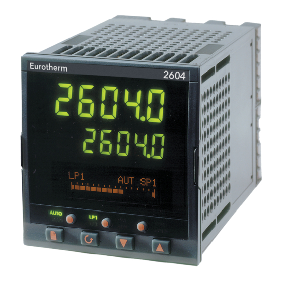
Eurotherm 2604 Manuals
Manuals and User Guides for Eurotherm 2604. We have
1
Eurotherm 2604 manual available for free PDF download: Installation And Operation Handbook
Eurotherm 2604 Installation And Operation Handbook (123 pages)
Brand:
Eurotherm
| Category:
Controller
| Size: 0 MB
Table of Contents
Table of Contents
4
Chapter 1 INTRODUCTION
5
What Is 2604
5
Before You Begin
6
Unpacking
6
Contents of Packaging
6
Does the Controller Match the Process
6
Operator Interface - Overview
8
LED Status Indicators
9
Operator Buttons
10
Installation - Overview
11
Chapter 2 Installation
14
Appendix B
15
Mechanical Installation
15
Outline Dimensions Model 2604
15
Positioning
15
Mounting the Controller
16
Unplugging and Plugging in the Controller
16
Electrical Connections
17
Rear Terminal Layout
17
Wiring
17
Appendix C
18
Standard Connections
19
Power Supply Wiring
19
Relay Output
20
Sensor Input Connections
21
Analogue Input Connections
22
I/O Expander (or Additional Digital Input)
23
Digital I/O
24
Optional Plug in Module Connections
25
Digital Communications Connections
25
Devicenet Wiring
27
Master/Slave Communications
29
I/O Modules
31
To Connect Zirconia (Dual Signal) Probe
37
Zirconia Probe Screening
38
Chapter 3 Principle of Operation
40
Power up
42
The HOME Page
42
The Operator Buttons
43
The Auto Manual Button
44
The Run/Hold Button
44
Lp1 Lp3
45
Lp2 Aux
45
The Loop Select Button
45
To Change Output Power (When the Loop Is in Manual)
46
To Change Setpoint (When the Loop Is in Auto)
46
Pages
47
Parameters and How to Access Them
47
Sub-Headers
48
To Step through
48
To Step through Parameters
49
To Change Parameter Values
50
Parameter Tables
52
Specific Displays for Cascade, Ratio, Override and Valve Position
53
Loop Summary Parameters
54
Backpage
55
Backscroll
55
Invalid Key Actions
55
Jump to Home Display
55
Parameter Availability and Alterability
56
Chapter 4 Programmer Operation
58
Customisable Parameter Names
59
What Is Setpoint Programming
60
Hold
61
Hot Start
61
Power Fail Recovery
61
Reset
61
Run
61
Servo
61
Setpoint Programmer Definitions
61
External Program Inputs
62
Holdback (Guaranteed Soak)
62
Wait
63
Profile
64
Programmer Types
64
Ramp Rate Programmer
64
Segment Types
64
Time to Target Programmer
64
End Segment
65
Go Back Segment
65
Other Features Not Covered in this User Guide
65
Programmer Operation
66
To Run, Hold or Reset a Program
66
Run Parameters
67
To Create or Edit a Program
71
To Define Parameters Common to a Program
72
PROGRAM EDIT (Program Page) Parameters
73
To Set up each Segment of a Program
75
PROGRAM EDIT(Segment Page) Parameters
76
Examples
78
Program Data Entry Example in a Ramp Rate Programmer
78
Prog Data Entry Example - Time to Target Programmer
80
Holdback Example
81
Wait Example
82
Program Names Example
84
Chapter 5 Alarm Operation
86
Customisable Parameter Names
87
Definition of Alarms and Events
87
Types of Alarm Used in 2604 Controller
88
Grouped Alarms
89
How Alarms Are Indicated
90
To Acknowledge an Alarm
90
Alarm Delay Time
91
Alarms (Summary) Parameters
93
Alarm Acknowledgement
94
To Set Alarm Trip Levels
96
Alarm Parameters
97
ALARMS (LP1 Page) Parameters
97
ALARMS (an Input Page) Parameters
98
ALARMS (PV Input Page) Parameters
98
Appendix B Safety and Emc Information
104
Appendix B Safety and Emc Information
105
Safety
105
Electromagnetic Compatibility
105
Service and Repair
105
Electrostatic Discharge Precautions
105
Cleaning
105
Installation Safety Requirements
106
Safety Symbols
106
Personnel
106
Enclosure of Live Parts
106
Isolation
106
Wiring
107
Power Isolation
107
Earth Leakage Current
107
Overcurrent Protection
108
Voltage Rating
108
Conductive Pollution
108
Over-Temperature Protection
109
Grounding of the Temperature Sensor Shield
109
Installation Requirements for Emc
109
Routing of Wires
109
Appendix C Technical Specification
110
Appendix C Technical Specification
111
All Analogue, Dual and Pv Inputs
111
Precision Pv Input / Module
112
Dual (Probe) Input Module
112
Analogue Input
113
Analogue Input Module
113
Standard Digital I/O
114
Digital Input Modules
114
Digital Output Modules
114
Analogue Output Modules
114
Transmitter Psu
114
Transducer Psu
115
Dual DC Output
115
High Resolution DC Output
115
Potentiometer Input
115
Digital Communications
115
Alarms
115
User Messages
116
Control Functions
116
Setpoint Programmer
116
Advanced Functions
116
General Specification
117
Graphical Representation of Errors
118
MV Input
118
MID Range High Impedance Input
119
High Level Input
120
RTD (Pt-100) Input Type
121
Thermocouple Input Type
123
Advertisement
Advertisement
Related Products
Eurotherm Invensys 2408
Eurotherm Invensys 2404
Eurotherm 2704
Eurotherm 2416
Eurotherm 2500
Eurotherm 2132i
Eurotherm 2208e
Eurotherm 2208L
Eurotherm 2408i
Eurotherm 2216L
Eurotherm Categories
Controller
Temperature Controller
Voice Recorder
Measuring Instruments
Media Converter
More Eurotherm Manuals
Login
Sign In
OR
Sign in with Facebook
Sign in with Google
Upload manual
Upload from disk
Upload from URL