Table of Contents
Advertisement
Quick Links
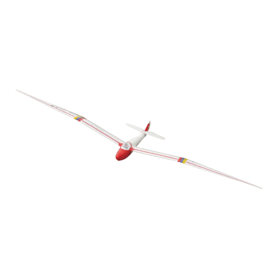
MINIMOA
Requires: 5-channel radio w/ 3 standard servos
Wing Span
Wing Area
Flying Weight
Fuselage Length
Warning! This model is not a toy.
It is designed for maximum performance. Please seek advice if one is not familiar with this kind
of engine powered precision model. Operating this model without prior preparation may cause
injuries. Remember, safety is the most important thing. Always keep this instruction manual at
hand for quick reference.
The World Models
Manufacturing Co., Ltd.
www.theworldmodels.com
G106PO31211604
and 4 mini servos
Specifications
*Specifications are subject to change without notice.*
134.0 in / 3400 mm
1175 sq in / 75.5 sq dm
7.5 Ib / 3400 g
54.0 in / 1370 mm
ALMOST-READY-TO-FLY(ARF)SERIES
INSTRUCTION MANUAL
( G106 )
FACTORY PRE-FABRICATED
MADE IN CHINA
Advertisement
Table of Contents

Related Manuals for The World Models Manufacturing MINIMOA


Summary of Contents for The World Models Manufacturing MINIMOA
- Page 1 INSTRUCTION MANUAL MINIMOA ( G106 ) Requires: 5-channel radio w/ 3 standard servos and 4 mini servos Specifications Wing Span 134.0 in / 3400 mm Wing Area 1175 sq in / 75.5 sq dm Flying Weight 7.5 Ib / 3400 g Fuselage Length 54.0 in / 1370 mm...
-
Page 2: Before You Begin
MINIMOA INDEX BEFORE YOU BEGIN PARTS LIST ASSEMBLY P.3-P.10 SAFETY PRECAUTIONS P.10 BEFORE YOU BEGIN Read through the manual before you begin, so you will have an overall idea of what to do. Check all parts. If you find any defective or missing parts contact your local dealer. Please DRY FIT and check for defects for all parts that will require CA or Epoxy for final assembly. -
Page 3: Parts List
Parts List DECALS: G106 DEC -- 1 set 9. SCREW HM4x52mm -- 1 pc. MAIN WING -- 1 pair WHEEL Ø70mm -- 1 pc. FUSELAGE -- 1 pc. M4 NYLON INSERT LOCK NUT -- 1 pc. RUDDER -- 1 pc. COLLAR Ø4.1mm w/ Set Screw -- 2 set COPPER TUBE d4xD5x6.5mm -- 2 pcs MAIN WING -- 1 set... - Page 4 Decals Cut out decal sheet, peel off backing sheet and apply on fuselage and wings. Decal Main wings Fuselage Left View Right View Rudder Right View Left View G106PO31211604...
- Page 5 Main Wing Apply instant type CA glue to both sides of each hinge. Ailer on Ser v o & Spoiler Servo Lead Bottom View Aileron & Spoiler Servos Ø1mm pilot holes for World Models horn are pre-drilled. Please look for pin-hole PB2x20mm Screw marks at under side of control surfaces.
-
Page 6: Stabilizer & Elevator
Main Wing Wing Joiner(B) Wing Joiner(B) Down Wing Joiner(B) Lead to Aileron Servo 8x13x244mm Stabilizer & Elevator M3x35mm Socket Head Screw d3xD12mm Washer (Stabi l i zer) (Mai n Wi ng) A=A' B=B' Temporary install the main wing, adjust leveling of the stabilizer to make it as parallel to the main wing as possible. -
Page 7: Rudder Pushrod
Vertical Fin & Rudder Apply instant type CA glue C=C' to both sides of each hinge. Completed Rudder Pushrod M2x48mm M2 Nut TWM PL8210010 CLEVIS WRENCH M2 Nut Fuel Tube D6x5mm Clevis Pushrod Ø1.8x1030mm Horn Rod M2x48mm Bottom View M2 Nut Elevator Pushrod PB2x25mm Screw TWM PL8210010... -
Page 8: Radio Equipment
Wheel 4.1mm Collar HM4x52mm Screw Nylon Insert Lock Nut d4xD9mm Washer 4.1mm Collar Set Screw Wheel Ø70mm Set Screw Copper Tube Nylon Insert Lock Nut Washer d4xD9mm Bottom View HM4x52 mm Radio Equipment Front 3x3mm Throttle Pushrod Washer Aerotow Release Pushrod Washer Ø2x215mm... -
Page 9: Main Wings
Main Wings Lead to Ailer on Ser v o & Spoiler Servo Set Screw Wing Tube Set Screw Set Screw Set Screw Completed Canopy PWA2.3x8mm Screw Silicon Grommet d1.5xD6.5mm Silicon Grommet PWA2.3x8mm d1.5xD6.5mm Pilot Completed G106PO31211604... - Page 10 Wing Seting Adjust the wing and fuselage configuration as shown in the diagrams. A=A' B=B' C=C' G106PO31211604...
-
Page 11: Control Throws
Control Throws Adjust the control throws as shown in the diagram. These throws are good for general flying. You can adjust according to your personal preference. Elevator 27mm 27mm Rudder 60mm 60mm Ailerons 14mm 14mm C.G. The ideal C.G. position is 115mm ( 4.53 in. ) behind the leading edge measured at where the wing meets the fuselage. - Page 12 LINKAGE CONNECTOR HW7111050 & HW7111060 Drill 2mm hole at servo horn. Insert linkage connector into servo horn. Make sure shoulder of screw is cleared from servo horn. Add washer to reduce play if necessary. Shoulder Tighten up the round nut against the shoulder.
- Page 13 Product Registration Form (US Customers) We would like to share with you any relevant information regarding your model, including product news and free upgrade parts when applicable. Please fill in the following and send to AirBorne Models, 4749-K,Bennett Drive, Livermore, CA 94551 USA. 1.
- Page 14 180mm Extension Wind sock Package Package Code No. Size Code No. AT3001052 Size AT3001052 D260x900mm 1 pc Package Code No. Size Package Code No. Size Large Clevis Small Clevis Special tool for clevis installation. Suitable for standard and small (EP)clevis. Code No SV4031 Package Code No.
- Page 15 G106PO31211604...
- Page 16 The World Models Manufacturing Co., Ltd. www.theworldmodels.com G106PO31211604...
Need help?
Do you have a question about the MINIMOA and is the answer not in the manual?
Questions and answers