Table of Contents
Advertisement
Quick Links
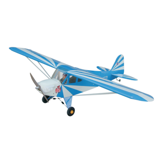
CLIPPED WING CUB - 48C
0.40-0.46 cu. in. displacement 2-stroke
0.52-0.56 cu. in. displacement 4-stroke
Requires:4-channel radio w/ 5 standard servos
Wing Span
Wing Area
Flying Weight
Fuselage Length
Warning! This model is not a toy.
It is designed for maximum performance. Please seek advice if one is not familiar with this kind
of engine powered precision model. Operating this model without prior preparation may cause
injuries. Remember,safety is the most important thing. Always keep this instruction manual
at hand for quick reference.
A001CPO23321005
Specifications
Specifications are subject to change without notice.
INSTRUCTION MANUAL
63.0 in / 1600 mm
620 sq in / 40 sq dm
5.5 lbs / 2500 g
47.0 in /1200 mm
FACTORY PRE-FABRICATED
ALMOST-READY-TO-FLY (ARF) SERIES
MADE IN CHINA
Advertisement
Table of Contents

Related Manuals for The World Models Manufacturing CLIPPED WING CUB - 48C


Summary of Contents for The World Models Manufacturing CLIPPED WING CUB - 48C
- Page 1 INSTRUCTION MANUAL CLIPPED WING CUB - 48C 0.40-0.46 cu. in. displacement 2-stroke 0.52-0.56 cu. in. displacement 4-stroke Requires:4-channel radio w/ 5 standard servos Specifications Wing Span 63.0 in / 1600 mm Wing Area 620 sq in / 40 sq dm Flying Weight 5.5 lbs / 2500 g...
-
Page 2: Before You Begin
CLIPPED WING CUB - 48C I N D E X BEFORE YOU BEGIN P. 1 PARTS LIST P. 2 ASSEMBLY P.3-P.10 SAFETY PRECAUTIONS P. 10 BEFORE YOU BEGIN Read through the manual before you begin, so you will have an overall idea of what to do. -
Page 3: Parts List
Parts List 1. MAIN WING -- 1 pair 12. SCREW PA1.7x8mm -- 6 pcs MAIN WHEEL PL3112080 -- 2 sets 2. SCREW PWA2x8mm -- 8 pcs COLLAR Ø3.3mm w/ set screw -- 4 sets PLYWOOD 2x52x80mm (For Aileron Servo) -- 1 pair SCREW PM2x8mm -- 6 pcs BALSA 8x18x21mm (For Aileron Servo) -- 4 pcs WASHER d2xD5mm -- 6 pcs... - Page 4 Main Wing Aileron Servo Lead Bottom View Pre-glued Main Wing Balsa Screw PWA2X8mm 8x18x21mm PWA2x8mm Make a slot into the hatch for the servo horn to come out. Plywood 2x50x80mm Bottom View Ø1mm pilot holes for The World Models tri-horn are pre-drilled. Main Wing Please look for pin-hole marks at under side of control surfaces.
- Page 5 Main Wing Ø9.6x246mm Plywood 2x30x120mm Join the wing halves by using the aluminium tube supplied Strengthen both holes for the screws with a piece of plywood . 558mm Wing Struts 95mm 189mm HM3x18mm Screw HM3x18mm Thread Locker Bottom View Vertical Fin / Horizontal Stabilizer Temporary install the main wing, adjust (Stabilizer) leveling of the stabilizer to make it as...
- Page 6 Tail Landing Gear Screw PA3x12mm Set Screw 2mm Collar Screw PM2x12mm Aluminum Plate 3mm Set Screw PM2x12mm PA3x12mm Engine Mount M4x25mm Socket Head Screw Washe d4xD9mm Engine Mount PL5111050 M4x25mm Socket Head Screw d4xD9mm Washer Lead the 1.2mm throttle rod through the Engine plastic tube and attach the throttle rod to the throttle lever on the engine.
-
Page 7: Fuel Tank
Fuel Tank CABLE TE 1.5x4x400mm DOUBLE-SIDED TAPE 40x80mm C ompleted Main Landing Gear PA3 x 8mm HM3x16mm Screw HM3x16mm 2.5mm 2.5mm Screw PA3x8mm Washer Aluminum Plate 3mm Washer Main Landing Gear Set Screw Screw PA1.7X8mm 3mm Set Screw Copper clipper Collar 2mm Washer 2. - Page 8 Canopy Securely glue the windows to the fuselage. Screw PWA2.3x8mm Silicon Grommet d1.5x6.5mm d1.5x6.5mm Silicon Grommet PWA2.3x8mm Cowling Screw PWA2.6x12mm Please refer to the attached sheet for usage of the Silicon Grommet d1.5x6.5mm 1.5mm transparent 3D template. Fuselage Cowling PWA2.6x12mm d1.5x6.5mm Silicon Grommet PWA2.6x12mm Trim the cowling for the...
-
Page 9: Radio Equipment
Rudder&ElevatorPushrod Screw PB2 x 12mm Ø1mm pilot holes for The World Models tri-horn are pre-drilled. Please look for pin-hole marks at under side of control surfaces. Set the pushrods as shown in the diagram. PB2x12mm Elevator Fuel Tube Tri-horn Ø6x5mm Elevator Clevis Rudder... - Page 10 Cockpit PC001063B Screw PWA2x8mm PWA2x8mm Balsa 3x45x108mm 1.5mm Balsa 6x8x45mm HM4 x 30mm Main Wing/Wing Struts d4xD15mm Washer Screw HM4 x 30mm M3 Nylon Insert Lock Nut Washer d4xD15mm Screw HM3 x 10mm Nylon Insert Lock Nut HM3 x 10mm A001CPO23321005...
-
Page 11: Control Throws
In order to obtain the wing and fuselage configuration as in the Wing Setting diagrams, insert shim plates between the wing and fuselage if necessary. Securely attach the main wing C = C' D = D' A = A' B = B' Control Throws Adjust the control throws as shown in the diagram. - Page 12 Warning! Important Safety Precautions #First time flyer should never fly by himself / herself. Assistance from experienced flyer is absolutely necessary. #Pre-flight adjustment must be done before flying, it is very dangerous to fly a badly pre-adjusted aircraft. is specially designed to be powered by 2C 40 or 4C 52 CLIPPED WING CUB - 48 C engine,using a more powerful engine does not mean better performance.
- Page 13 LINKAGE CONNECTOR HW7111050 & HW7111060 Drill 2mm hole at servo horn. Insert linkage connector into servo horn. Make sure shoulder of screw is cleared from servo horn. Add washer to reduce play if necessary. Shoulder Tighten up the round nut against the shoulder.
- Page 14 A001CPO23321005...
-
Page 15: Optional Parts
Optional Parts ACCESSORIES 180mm Extension Clevis Wrench Package Package Code No. Size Code No. Size PL8210010 1 set KW0011800 180mm 1 set Large Clevis Small Clevis Special tool for clevis installation. Suitable for standard and small (EP) clevis. 180mm Y Cord Package Code No. - Page 16 The World Models Manufacturing Co., LTD. www .thew orldm odels .com A001CPO23321005...
Need help?
Do you have a question about the CLIPPED WING CUB - 48C and is the answer not in the manual?
Questions and answers