Table of Contents
Advertisement
Quick Links
0.40
-0.46
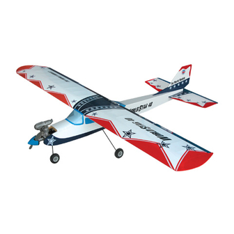
0.52 cu.in. displacement 4-stroke
Requires: 4-channel
Wing Span
Wing Area
Flying Weight
Fuselage Length
Warning ! This model is not a toy.
It is designed for maximum performance. Please seek advice if one is not familiar with this kind
of engine powered precision model. Operating this model without prior preparation may cause
injuries. Remember, safety is the most important thing. Always keep this instruction manual at
hand for quick reference.
A113FPO25541103
cu.in. displacement 2-stroke
* Specifications are subject to change without notice.*
The World Models
Manufacturing Co., Ltd.
w w w. t h e w o r l d m o d e l s . c o m
radio
w/ standard servos
5
Specifications
67 in / 1700mm
733 sq in / 47.3 sq dm
5.5-6.2 lbs / 2500-2800g
53 in / 1350mm
INSTRUCTION MANUAL
FACTORY PRE-FABRICATED
ALMOST-READY-TO-FLY (ARF) SERIES
MADE IN CHINA
Advertisement
Table of Contents

Subscribe to Our Youtube Channel
Related Manuals for The World Models Manufacturing WORLDSTAR 40 F


Summary of Contents for The World Models Manufacturing WORLDSTAR 40 F
- Page 1 INSTRUCTION MANUAL 0.40 -0.46 cu.in. displacement 2-stroke 0.52 cu.in. displacement 4-stroke Requires: 4-channel radio w/ standard servos Specifications 67 in / 1700mm Wing Span Wing Area 733 sq in / 47.3 sq dm Flying Weight 5.5-6.2 lbs / 2500-2800g Fuselage Length 53 in / 1350mm * Specifications are subject to change without notice.* Warning ! This model is not a toy.
-
Page 2: Before You Begin
I N D E X BEFORE YOU BEGIN P. 1 PARTS LIST P. 2 ASSEMBLY P. 3 - 11 SAFETY PRECAUTIONS P. 11 BEFORE YOU BEGIN Read through the manual before you begin, so you will have an overall idea of what to do. Check all parts. -
Page 3: Parts List
Parts List 1. MAIN WING -- 1 pair 13. SCREW PB2x12mm -- 2 pcs HORN (L) PL4113101 -- 1 set 2. WING TUBE Ø16x296mm -- 1 pc. CLEVIS (L) PL4112103 -- 1 pc. 3. SCREW PB2x16mm -- 4 pcs FUEL TUBE Ø6x5mm -- 1 pc. RING Ø2.6mm -- 2 pcs PUSHROD Ø1.8x765mm w/ Threads (For Rudder) -- 1 pc. -
Page 4: Aileron Servo
Main Wing Pre-glued Main Wing Wing Tube Ø16x296mm Completed This step is for one-piece aileron. Aileron Servo You may follow step 3a if you want to use flaps. Plywood 3 x 10 x 21mm 1.5mm Ring Straper Fuel Tube Ø6x5mm Clevis Ring A113FPO25541103... - Page 5 Aileron & Flap Servo If you want to use flaps, please follow this step. Peel off shaded portion covering film. 320mm 320mm PB2x16mm Screw Straper 1.5mm PB 2x16mm Fuel Tube Ø6x5mm Clevis Ø1.8x105mm Horn Completed 1.5mm Straper Fuel Tube Ø6x5mm Clevis Ring 1.5mm...
-
Page 6: Stabilizer & Elevator
Stabilizer & Elevator Pre-glued Bottom View Vertical Fin & Rudder PM3x45mm Screw Pre-glued d3x12mm Washer PM3x50mm Screw PM3x50mm Use thread locker when tightening d3x12mm Washer screws. Don't use excessive force as you are dealing with balsa. PM3x45mm If you want a tail dragger landing gear, follow Tail Landing Gear this step and 10B. -
Page 7: Engine Mount
Fuel Tank DOUBLE-SIDED TAPE 40x100mm CABLE TIE 1.5x5x400mm Engine Mount M3 x 25mm Socket Head Screw M3 x 25mm Socket Head Screw Wa s h e r d 3 x D 7 m m d 3 x D 7 m m Engine Mount PL5111030 Apply thread locker to screws. -
Page 8: Main Landing Gear
PA3x12mm PA3x12mm Main Landing Gear PA3x12mm Screw For No.10A For No.10B (Tricycle landing gear) Fr ont (Tail dragger landing gear) 4.1mm Collar Main Wheels 4.1mm Collar 3mm Set Screw Installed Engine Position Engine Spinner Ø57mm PM2x10mm Screw Throttle Pushwire Plastic tube d2xD5mm Washer 104mm 4.1in. -
Page 9: Rudder Pushrod
Rudder Pushrod Rudder Pushrod Ø1.8x765mm Ø1mm pilot holes for World Models horn are pre-drilled. Please look for pin-hole marks at under side of control surfaces. Horn PB2x12mm Elevator Pushrod Elevator Pushrod PB2x12mm Ø1.8x755mm Ø1mm pilot holes for World Models horn are pre-drilled. Please look for pin-hole marks at under side of Horn control surfaces. -
Page 10: Radio Equipment
PLYWOOD Elevator Pushrod 3x10x21mm Servos Straper Rudder Pushrod Fuel Tube Ø6x5mm PLYWOOD 3x85.4x95mm BALSA 6x6x92mm Throttle Pushwire 3x40x87mm Ø1.2x500mm Plastic Tube d2xD3x380mm Front Wheel Pushwire Ø1.2x450mm Plastic Tube d2xD3x380mm BALSA BALSA 7x7x40mm 7x7x40mm Radio Equipment Install Sponge for inserting Battery and Receiver. PLYWOOD 3x40x90mm Battery... -
Page 11: Control Throws
Canopy PWA2.3x8mm Screw d1.5xD6.5mm Silicon Grommet PWA2.3x8mm Silicon Grommet d1.5xD6.5mm Wing Setting Adjust the wing and fuselage configuration as shown in the diagrams. Adjust the control throws as shown in the diagram. Control Throws These throws are good for general flying. You can adjust according to your personal preference. - Page 12 C.G. The ideal C.G. position is 90mm (3.54 in.) behind the leading edge measured at where the wing meets the fuselage. In order to obtain the C.G. specified, add weight to the fuselage or move the battery position. Check the C.G. before flying. 90mm 3.54in.
- Page 13 LINKAGE CONNECTOR HW7111050 & HW7111060 Drill 2mm hole at servo horn. Insert linkage connector into servo horn. Make sure shoulder of screw is cleared from servo horn. Add washer to reduce play if necessary. Shoulder Tighten up the round nut against the shoulder.
- Page 14 Product Registration Form (US Customers) We would like to share with you any relevant information regarding your model, including product news and free upgrade parts when applicable. Please fill in the following and send to AirBorne Models, 4749-K, Bennett Drive, Livermore, CA 94551 USA. 1.
-
Page 15: Optional Parts
Optional Parts ACCESSORIES) Fuel Filler 180mm Extension For Park Flyer Code No. Size Package Code No. Size Package PL8110030 KW0011800 180mm 1 set 15 x 22 x 49mm 1 x 1 pc 180mm Y-Cord For Park Flyer Package Code No. Size KW0021800 180mm 1 pc... - Page 16 The World Models M a n u f a c t u r i n g C o . , L t d . w w w. t h e w o r l d m o d e l s . c o m A113FPO25541103...
Need help?
Do you have a question about the WORLDSTAR 40 F and is the answer not in the manual?
Questions and answers