Table of Contents
Advertisement
Quick Links
Download this manual
See also:
Instruction Manual
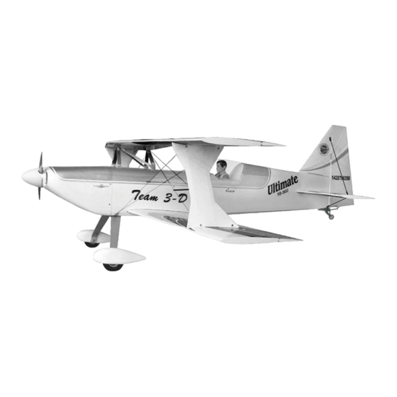
42%
42%
Requires : 150-200 c.c. engine, 6 channel radio
Wing Span
Wing Area
Flying Weight
Fuselage Length
Warning !This model is not a toy.
It is designed for maximum performance. Please seek advice if one is not familiar with this kind
of engine powered precision model. Operating this model without prior preparation may cause
injuries. Remember, safety is the most important thing. Always keep this instruction manual at
hand for quick reference.
w/ 17 high torque servos.
Specifications
* Specifications are subject to change without notice.*
98 in / 2490 mm
3300 sq in / 213 sq dm
38-40 lbs / 17250-18160 g
104 in / 2640 mm
ALMOST-READY-TO-FLY (ARF) SERIES
INSTRUCTION MANUAL
FACTORY PRE-FABRICATED
MADE IN CHINA
Advertisement
Table of Contents

Related Manuals for The World Models Manufacturing 42% ULTIMATE


Summary of Contents for The World Models Manufacturing 42% ULTIMATE
- Page 1 INSTRUCTION MANUAL Requires : 150-200 c.c. engine, 6 channel radio w/ 17 high torque servos. Specifications Wing Span 98 in / 2490 mm Wing Area 3300 sq in / 213 sq dm Flying Weight 38-40 lbs / 17250-18160 g Fuselage Length 104 in / 2640 mm * Specifications are subject to change without notice.* Warning !This model is not a toy.
-
Page 2: Before You Begin
I N D E X BEFORE YOU BEGIN P. 1 PARTS LIST P. 2 ASSEMBLY P. 3 - 11 SAFETY PRECAUTIONS P. 11 BEFORE YOU BEGIN Read through the manual before you begin, so you will have an overall idea of what to do. Check all parts. - Page 3 Parts List 9. MAIN LANDING GEAR -- 1 set 1. MAIN WING (LOWER WING) -- 1 pair ALUMINUM PLATE -- 2 pcs MAIN WING (UPPER WING) -- 1 pair WHEEL PANTS -- 1 pair SOCKET HEAD SCREW M6x20mm -- 4 pcs 2.WOODEN 6x10x21mm (For Aileron Servo Stand) -- 8 pcs SCREW PA3x12mm -- 4 pcs 3.
-
Page 4: Aileron Servo
Main Wing Replace CA hinges by metal hinges. Glue the metal hinges to wing and aileron by epoxy. Main Wing (Lower) Main Wing (Upper) Aileron Servo Lead Aileron Servo Lead Bottom View Bottom View Aileron Servo (Upper Wing) PM2x8mm Heavy Duty Horn Bracket M4 Nylon Insert Lock Nut M2 Nut... -
Page 5: Stabilizer & Elevator
Aileron Servo (Lower Wing) Similar installation as upper wing. Bottom View PWA3x14mm Stabilizer & Elevator Screw PWA3 X 14mm 76mm Stabilizer Tube Ø22x514mm Bottom View Wooden 6x10x21mm Wire Ø3x192mm M2 Nut PM2x8mm Heavy Duty Clevis Heavy Duty Horn Bracket M4 Nylon Insert Lock Nut Bottom View M2 Nut... -
Page 6: Tail Landing Gear
Vertical Fin & Rudder B=B' Replace CA hinges by metal hinges. Glue the metal hinges to vertical and rudder by epoxy. Completed Tail Landing Gear PA3 x14mm PWA2 x 12mm 1.5mm COPPER PLATE Bottom View... - Page 7 Engine Box F8(8x127x571mm) F8' (8x127x563mm) Please note right thrust angle of firewall. M3 Nylon Insert Lock Nut Use epoxy to Completed glue all parts together. F63C...
-
Page 8: Main Landing Gear
Wing Cabane d3xD7mm M3 Nylon Inert Lock Nut Washer d3xD7mm Washer F36A Nylon Inert Lock Nut F36B d3xD7mm Washer d3xD7mm Washer d3xD7mm d3xD7mm Washer Washer Main Landing Gear M6x20mm SOCKET HEAD SCREW M6x20mm SOCKET HEAD SCREW Screw PA3x12mm PA3x12mm Aluminum Plate Bottom View... -
Page 9: Rudder Pushrod
Rudder Pushrod Heavy Duty Horn Bracket M4 Nylon Insert Lock Nut M2 Nut Heavy Duty Clevis PA1.7x8mm 3.7mm M4 Tap Drill and tap the swivel PM2x8mm clevis horn locations for Pushrod M4 machine screw. Bottom View Bottom View Flying Wire Copper Tube Press down the center 1/3 portion... -
Page 10: Fuel Tank
Fuel Tank Engine Center line of firewall 10mm 63mm Engine thrust line Radio Equiment Install and arrange the receiver and battery as shown in the diagram. Front Sponge... - Page 11 Step 1. Insert the aluminum wing tube (Ø22x865.5mm) with the pre-drilled hole end into the right wing (lower). Main Wing Align the lines marked at the wing root and wing tube, then apply the PM3x22mm machine screw through the (Lower) pre-drilled hole on top of the wing.
- Page 12 Step 1. Insert the aluminum wing tube (Ø22x817mm) with the pre-drilled hole end into the right wing (upper). Main Wing Align the lines marked at the wing root and wing tube, then apply the PM3x22mm machine screw through the (Upper) pre-drilled hole on top of the wing.
- Page 13 Outer Wing Cabanes & Flying Wire With the wing incidence angle template still in place, position the side cabanes, Outer wing cabane mark and drill the side should fit to the outside of outer cabane mounts and fasten wing cabane mounts. with PM3x18mm screw and nut.
- Page 14 First insert the grommet to the cowling then apply screw. Cowling & Spinner Wing Setting Adjust the wing and fuselage configuration as in the diagrams. A=A' B=B' C=C' D=D' E=E' F=F' G=G' P.13...
-
Page 15: Control Throws
Adjust the control throws as shown in the diagram. Control Throws These throws are good for general flying. You can adjust according to your personal preference. Elevator 40mm 40mm Rudder 85mm 85mm Ailerons 30mm 30mm The ideal C.G. position is at center of top wing. You can Check the C.G. - Page 16 The World Models Manufacturing Co., LTD. www .thew orldm odels .com A151SPO11310906...
Need help?
Do you have a question about the 42% ULTIMATE and is the answer not in the manual?
Questions and answers