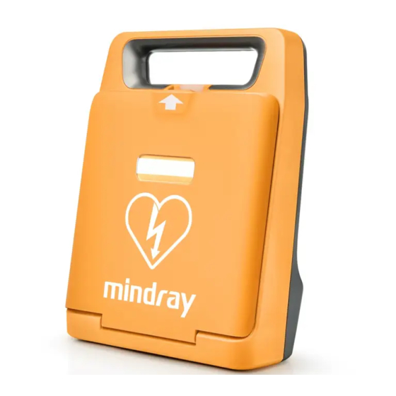
Mindray BeneHeart C  Series Operator's Manual

Mindray BeneHeart C Series Operator's Manual

Automatic external defibrillator
Table of Contents

Advertisement

Quick Links

BeneHeart C & BeneHeart S Series
Automatic External Defibrillator
Operator's Manual
(BeneHeart C1/BeneHeart C1A/BeneHeart C2/BeneHeart C2A/
BeneHeart C1 Fully Automatic/BeneHeart C1A Fully Automatic/
BeneHeart C2 Fully Automatic/BeneHeart C2A Fully Automatic/
BeneHeart S1/BeneHeart S1A/BeneHeart S2/BeneHeartS2A/
BeneHeart S1 Fully Automatic/BeneHeart S1A Fully Automatic/
BeneHeart S2 Fully Automatic/BeneHeart S2A Fully Automatic)

Advertisement

Table of Contents
loading
Need help?

Need help?

Do you have a question about the BeneHeart C Series and is the answer not in the manual?

Questions and answers

Subscribe to Our Youtube Channel

Summary of Contents for Mindray BeneHeart C Series

  • Page 1 BeneHeart C & BeneHeart S Series Automatic External Defibrillator Operator’s Manual (BeneHeart C1/BeneHeart C1A/BeneHeart C2/BeneHeart C2A/ BeneHeart C1 Fully Automatic/BeneHeart C1A Fully Automatic/ BeneHeart C2 Fully Automatic/BeneHeart C2A Fully Automatic/ BeneHeart S1/BeneHeart S1A/BeneHeart S2/BeneHeartS2A/ BeneHeart S1 Fully Automatic/BeneHeart S1A Fully Automatic/ BeneHeart S2 Fully Automatic/BeneHeart S2A Fully Automatic)
  • Page 3 © Copyright 2019 Shenzhen Mindray Bio-Medical Electronics Co., Ltd. All rights reserved. ■ Release time: July 2019 ■ Revision: 2.0...
  • Page 4 SHENZHEN MINDRAY BIO-MEDICAL ELECTRONICS CO., LTD. (hereinafter called Mindray) owns the intellectual property rights to this Mindray product and this manual. This manual may refer to information protected by copyright or patents and does not convey any license under the patent rights or copyright of Mindray, or of others.
  • Page 5 Mindray's obligation or liability under this warranty does not include any transportation or other charges or liability for direct, indirect or consequential damages or delay resulting from the improper use or application of the product or the use of parts or accessories not approved by Mindray or repairs by people other than Mindray authorized personnel.
  • Page 6 Preface Manual Purpose This manual contains the instructions necessary to operate the product safely and in accordance with its function and intended use. Observance of this manual is a prerequisite for proper product performance and correct operation and ensures patient and operator safety. This manual is based on the maximum configuration and therefore some contents may not apply to your product.
  • Page 7: Table Of Contents

    Contents 1 Safety ....................................1 - 1 1.1 Safety Information ......................................1 - 1 1.1.1 Dangers .........................................1 - 1 1.1.2 Warnings ......................................1 - 1 1.1.3 Cautions ........................................1 - 2 1.1.4 Notes ........................................1 - 2 1.2 Equipment Symbols .......................................1 - 3 2 Equipment Introduction ..............................2 - 1 2.1 Overview ..........................................2 - 1 2.2 Intended Use ........................................2 - 2 2.3 Applied Parts ........................................2 - 2...
  • Page 8 B Mindray Shockable Rhythm Analysis Algorithm ......................B - 1 B.1 Rhythm Recognition and Annotation Methodology .........................B - 1 B.1.1 Database for Evaluation of Mindray Algorithm Performance ..................B - 1 B.1.2 Rhythm Categories ...................................B - 1 B.2 Mindray Shockable Rhythm Analysis Algorithm Performance ......................B - 2...
  • Page 9 C EMC and Radio Regulatory Compliance ..........................C - 1 C.1 EMC ............................................. C - 1 C.2 Radio Regulatory Compliance ................................... C - 4 D Default Settings ................................D - 1 D.1 General Setup .........................................D - 1 D.2 AED Setup .........................................D - 2 D.3 CPR Setup .........................................D - 2 D.4 Test Setup .........................................D - 3 D.5 WLAN Setup ........................................D - 3...
  • Page 10 This page intentionally left blank.
  • Page 11: Safety

    Safety Safety Information DANGER • Indicates an imminent hazard that, if not avoided, will result in death or serious injury. WARNING • Indicates a potential hazard or unsafe practice that, if not avoided, could result in death or serious injury. CAUTION •...
  • Page 12: Cautions

    • Medical electrical equipment which does not incorporate defibrillator protection should be disconnected during defibrillation. • Do not defibrillate a patient who lies on wet ground. • For the treatment of patients with implantable pacemakers, place the electrode pads away from internal pacemaker generator if possible to help prevent damage to the pacemaker.
  • Page 13: Equipment Symbols

    Equipment Symbols Refer to instruction manual/ General warning sign booklet DEFIBRILLATION-PROOF TYPE BF Shock button APPLIED PART Manufacturer Date of manufacture Do not expose the battery to high Dust-protected heat or open flames. Do not Protected against water jets incinerate the battery. Do not mutilate the battery or Do not crush the battery.
  • Page 14 This page intentionally left blank. 1 - 4...
  • Page 15: Equipment Introduction

    Equipment Introduction Overview The BeneHeart C & S series automatic external defibrillator is designed for treating life-threatening heart beat irregularities. There are two types of product models provided: semi-automatic and fully automatic. Some of the series equipments are configured with the screen. Characteristics of the product models are detailed in the following table.
  • Page 16: Intended Use

    Intended Use The BeneHeart C & S series defibrillator, hereafter called the equipment, is intended to be used on adults and children in a sudden cardiac arrest. The patients must be: Unresponsive ■ Not breathing or not breathing normally ■ The equipment also guides the operator throughout cardiopulmonary resuscitation (CPR) with voice and/or visual guidance.
  • Page 17 Pad expiration window: checks the expiration date of pads. Latch: opens or closes the lid. Handle Status indicator • Green: the equipment is turned on, and can work correctly. • Flashing green: the equipment is in the standby status, and is ready for operation at any time.
  • Page 18: Bottom View

    2.4.2 Bottom View The battery compartment provides the following connectors. USB connector: connects the USB flash memory. micro USB connector: connects the computer. Network connector (for equipment configured with the cellular module): connects the SIM card. Battery compartment: stores the battery. 2.4.3 Back View Multifunction connector (for equipment configured with the CPR sensor:...
  • Page 19: Getting Started

    Getting Started Preparation Safety Information WARNING • The equipment shall be installed by personnel authorized by the manufacturer. • The software copyright of the equipment is solely owned by the manufacturer. No organization or individual shall resort to altering, copying, or exchanging it or to any other infringement on it in any form or by any means without due permission.
  • Page 20: Environmental Requirements

    3.2.2 Environmental Requirements The operating environment of the equipment must meet the requirements specified in this manual. The environment where the equipment is used shall be reasonably free from noises, vibration, dust, corrosive, flammable and explosive substances. If the equipment is installed in a cabinet, sufficient space in front and behind shall be left for convenient operation, maintenance and repair.
  • Page 21: Turning On The Equipment

    Turning on the Equipment Before turning on the equipment, perform the following inspections: Check for mechanical damage on the equipment or other damage on the pads package. ■ ■ Make sure the pads cable is properly connected and battery installed. ■...
  • Page 22 This page intentionally left blank. 3 - 4...
  • Page 23: Using The Equipment

    Using the Equipment Operating Safety Information DANGER • Avoid contact between parts of the patient’s body such as exposed skin of head or limbs, conductive fluids such as gel, blood, or saline, and metal objects such as a bed frame or a stretcher which may provide unwanted pathways for the defibrillating current.
  • Page 24: Screen Display (For Equipment Configured With The Screen)

    • Impedance is the resistance between the electrode pads that the defibrillator must overcome to deliver an effective discharge of energy. The degree of impedance differs from patient to patient and is affected by several factors including the presence of chest hair, moisture, and lotions or powders on the skin.
  • Page 25: Responds To A Rescue

    Responds to a Rescue You should perform the general steps for a rescue. Assess the Patient Confirm that the patient is both: • Unresponsive, • Not breathing or not breathing normally CALL EMERGENCY MEDICAL SERVICE! Turn on the Equipment Open the lid. You hear: Powered on.
  • Page 26 Apply the Electrode Pads Apply the electrode pads to the patient as directed on the pads package. For an adult: • Blue (apex) pad placement: place the blue pad as the blue area (below left nipple, on the left anterior axillary line) illustrated in the picture •...
  • Page 27: Performing Cpr

    Perform CPR Perform CPR according to the prompts. • If the CPR time expires, repeat Step 6. • If the patient is conscious and breathing normally, wait for emergency medical services to arrive. Performing CPR The equipment enters the CPR status in the following conditions. Non-shockable rhythm is detected with a prompt “No shock advised ”.
  • Page 28: Preparation For Next Rescue

    Plug the other end of the sensor cable into the CPR sensor connector of the equipment. For more information on using the CPR sensor, see MR6401 CPR Sensor Operator’s Manual. Preparation for Next Rescue Retrieve the rescue data stored in the equipment. For more information, see 5 Data Management. Squeeze the pads connector, and hold it back to remove the pads connector.
  • Page 29: Data Management

    Data Management Data Management Overview The following table lists data stored in the equipment and how to manage these data. Data Type Description Management Method Patient Data ECG data Heart rhythm Contact your local distributor. Events AED analysis, CPR operation, system operations and prompts Recordings Audio recorded during a rescue...
  • Page 30: Aed Alert System Overview

    If the equipment is connected to the AED ALERT system through the wireless network, you can access the system on the Internet. To access the AED ALERT system, follow this procedure. Input https://aed-alert.mindray.com in the Browser address bar. Input the user name and password. Click [Login].
  • Page 31: Battery

    Battery Battery Introduction The equipment is designed to operate using a disposable battery. Battery Safety Information WARNING • Never charge the disposable battery under any circumstances. • Do not disassemble, puncture or incinerate batteries. Do not short the battery terminals. They may ignite, explode, or leak, causing personal injury.
  • Page 32: Battery Prompts

    6.3.2 Battery Prompts If the battery has low charge, voice prompts will be given. In this case, you should take actions by referring to the following table. Voice Prompt Recommended Action Low Battery! Please replace battery as The battery charge is low. Replace the battery with a new soon as possible battery immediately.
  • Page 33: Storing Batteries

    NOTE • Install and use the battery before the expiration date displayed on the battery label. • Never remove the battery unless the equipment indicates to do so. • Make sure the battery door is reinstalled properly to protect the equipment and battery. Storing Batteries When storing batteries, make sure that the battery terminals do not come into contact with metallic objects.
  • Page 34 This page intentionally left blank. 6 - 4...
  • Page 35: Care And Cleaning

    Warranty does not cover damages caused by unapproved cleaning and disinfection substances or methods. Mindray makes no claims regarding the efficacy of the listed chemicals or methods as a means for controlling infection. For the method to control infection, Mindray advises you to consult your local hospital’s Infection Control Officer or epidemiologist.
  • Page 36: Disinfecting

    Disinfecting Disinfect the equipment as required in your facility servicing schedule. Cleaning equipment before disinfecting is recommended. Sterilization Sterilization is not recommended for the equipment unless otherwise indicated in the Instructions for Use that accompany the product. 7 - 2...
  • Page 37: Maintenance And Testing

    • If you discover a problem with any of the equipment, contact your local distributor, service personnel or Mindray. • Use and store the equipment within the specified temperature, humidity, and barometric ranges. •...
  • Page 38: Performing Maintenance

    Performing Maintenance To ensure that the equipment is ready for operation at any time, perform the following tests as recommended: Maintenance Item Recommended Frequency Test Item User test • After installing the battery Performs function tests of the main control module, the therapy module, the power •...
  • Page 39: Auto Test

    Flashes in red: the auto test fails. If the equipment is connected to the AED ALERT system, an auto-test report is saved and uploaded automatically to the system when the test is completed. Mindray recommends you check the status indicator every day, and record the result according to G Inspection Record.
  • Page 40 This page intentionally left blank. 8 - 4...
  • Page 41: Accessories

    Accessories The accessories listed in this chapter comply with the requirements of IEC 60601-1-2 when in use with the equipment. The accessory material that contacts the patients has undertaken the bio-compatibility test and is verified to be in compliance with ISO 10993-1. For details about the accessories, refer to the instructions for use provided with the accessory.
  • Page 42: Miscellaneous

    Miscellaneous Description Model Disposable battery LM34S002A 022-000411-00 9 - 2...
  • Page 43: A Specifications

    Specifications Safety Specifications The equipment is classified, according to IEC 60601-1: Type of protection against Equipment energized from an internal electrical power source (battery). electrical shock Degree of protection against Type BF defibrillation proof for external defibrillation. electric shock Mode of operation Continuous Degree of protection against IP5X...
  • Page 44: Physical Specifications

    Drop 1.5 m per IEC 68-2-32, 1 on each of the six surfaces. CAUTION • The equipment may not meet the performance specifications if stored or used outside the specified temperature and humidity ranges. If the performance of the equipment is degraded due to aging or environmental conditions, contact your service personnel.
  • Page 45: Interface Specifications

    Interface Specifications USB connector 1, USB 2.0 micro USB connector 1, supports Windows 7 or above operating system Network connector 1, connects the Wi-Fi or cellular (2G/3G/4G) network. Multifunction connector 1, connects the CPR sensor. Battery Specifications Battery type Disposable battery Battery voltage Battery capacity 4200mAh...
  • Page 46: Data Storage

    Remaining charge after “Low For BeneHeart C1/BeneHeart C1A/BeneHeart C1 Fully Automatic/ Battery” is prompted BeneHeart C1A Fully Automatic/BeneHeart S1/BeneHeart S1A/BeneHeart S1 Fully Automatic/BeneHeart S1A Fully Automatic: • At least 30 minutes operating time (at 20 °C± 5 °C of ambient temperature, wireless function off, voice volume set to low) and at least 10 200J discharges (with one minute of CPR between discharges) •...
  • Page 47: Wireless Specifications

    25 to 300 Ω Shock series Energy level: 100 to 360J, configurable for adults. 10 to 100J, configurable for children. Shocks: 1, 2, 3, configurable; Meeting AHA/ECR guidelines 2015 by default. ECG Analysis Performance See B Mindray Shockable Rhythm Analysis Algorithm. A - 5...
  • Page 48 360 J defibrillation waveform into impedance of 25Ω, 50Ω, 75Ω, 100Ω, 125Ω, 150Ω, 175Ω Time (ms) Selected energy accuracy Impedance 25Ω 50Ω 75Ω 100Ω 125Ω 150Ω 175Ω Accuracy Energy 10 J 9.7 J 10 J 9.7 J 9.3 J 8.9 J 8.5 J 8.1 J ±10% or ±2J,...
  • Page 49: Ecg Specifications (For Equipment Configured With The Screen)

    A.11 ECG Specifications (for Equipment Configured with the Screen) ECG inputs Multifunction electrode pads Gain Auto 25 mm/s, error no more than ± 5% Sweep speed Common mode rejection >90 dB Recovery time <2.5 s (after defibrillation) A.12 Electrode Pads Specifications Electrode Pads MR60 MR61...
  • Page 50 This page intentionally left blank. A - 8...
  • Page 51: B Mindray Shockable Rhythm Analysis Algorithm

    Database for Evaluation of Mindray Algorithm Performance The database for evaluation of Mindray algorithm performance includes international standard database and Mindray clinical database for evaluating the ECG data. The ECG data for evaluation is selected according to AHA recommendations with a 10-second wave length.
  • Page 52: Mindray Shockable Rhythm Analysis Algorithm Performance

    Mindray Shockable Rhythm Analysis Algorithm Performance Test results on the performance of the equipment configured with Mindray shockable rhythm analysis algorithm meet IEC 60601-2-4 requirements and AHA recommendations Test results on IEC 60601-2-4 requirements are shown below. Rhythm category Requirement...
  • Page 53: C Emc And Radio Regulatory Compliance

    EMC and Radio Regulatory Compliance The equipment meets the requirements of IEC 60601-1-2: 2014. WARNING • Use of accessories, transducers and cables other than those specified or provided by the manufacturer of this device could result in increased electromagnetic emissions or decreased electromagnetic immunity of this device and result in improper operation.
  • Page 54 If the device is operated within the electromagnetic environment listed in Table Guidance and Declaration - Electromagnetic Immunity, the equipment will remain safe and provide the following essential performance: energy accuracy, CPR function, data stored. Guidance and Declaration - Electromagnetic Immunity The equipment is suitable for use in the electromagnetic environment specified below.
  • Page 55 Note 1: At 80 MHz and 800 MHz, the higher frequency range applies. Note 2: These guidelines may not apply in all situations. Electromagnetic propagation is affected by absorption and reflection from structures, objects and people. The ISM (industrial, scientific, and medical) bands between 150 kHz and 80 MHz are 6.765 MHz to 6.795 MHz;...
  • Page 56: Radio Regulatory Compliance

    Radio Regulatory Compliance Wi-Fi Operating frequency IEEE 802.11 b/g/n (at 2.4G): 2.412 GHz to 2.472 GHz IEEE 802.11 a/n (at 5G): 5.18 GHz to 5.24 GHz, 5.745 GHz to 5.825 GHz Modulation mode DSSS and OFDM Output Power ≤20 dBm Cellular Operating frequency LTE-FDD B1: 1920 MHz to 1980 MHz, 2110 MHz to 2170 MHz...
  • Page 57: D Default Settings

    Default Settings The following tables list all configurable setup options for the equipment with all functions. Your equipment may not have all of them. General Setup Menu Item Description Options/Range Default System Year Sets the system date. 2007 to 2099 Date Configurable range: 2007-01- Month...
  • Page 58: Aed Setup

    AED Setup Menu Item Description Options/Range Default Shock Series Sets the number of shocks. 1, 2, 3 If it is set to greater than one, the equipment resumes analyzing the patient’s rhythm after the shock is delivered to determine if the shock was successful.
  • Page 59: Test Setup

    If the equipment is configured with the Wi-Fi module, the related setup options are shown as below. Menu Item Description Options/Range Default Device Management Input the IP address or aed-alert.mindray.com System Site domain name of AED ALERT system Device Management Input the port of AED ALERT 0 to 65535...
  • Page 60: Aed Alert Related Setup

    AED ALERT Related Setup If the equipment is connected to the AED ALERT system through the wireless network, the related setup options are shown as below. Menu Item Description Options/Range Default Device Enabled Sends messages to the On, Off Reminder designated person on the AED ALERT system when the equipment is turned on,...
  • Page 61: E Voice Prompts

    Voice Prompts The following table lists voice prompts that may occur during a rescue. Condition Voice Prompt Description Open the lid Powered on. Stay calm. Follow the The lid is opened. instructions. Device error. Recommended to replace The equipment malfunctions, use the Device.
  • Page 62 Condition Voice Prompt Description The equipment Shock advised. Everyone clear. Notifies a shockable rhythm has delivers a shock. been detected. Shock will be delivered in: 3, 2, 1 Prompts the equipment is fully charged and is preparing to deliver a defibrillation shock. Shock delivered.
  • Page 63 Condition Voice Prompt Description Perform CPR Push down hard. Prompts to use more effort for compressions. Continue to push down hard. Stop CPR. Prompts to stop CPR. Continue with compressions. Prompts to continue CPR. Give two rescue breaths. Prompts to give breath to the patient.
  • Page 64 This page intentionally left blank. E - 4...
  • Page 65: F Symbols And Abbreviations

    Symbols and Abbreviations Units μA microampere μV microvolt ampere ampere hour beat per minute bit per second ºC centigrade centimeter decibel ºF fahrenheit hour hertz inch Joule kilogram kilopascal litre meter minute millimeter millisecond millivolt milliwatt breaths per minute second volt Ω...
  • Page 66: Symbols

    Symbols – negative, minus percent per; divide; or plus equal to < less than > greater than ≤ less than or equal to ≥ greater than or equal to ± plus or minus × multiply © copyright Abbreviations and Acronyms AAMI Association for Advancement of Medical Instrumentation adult...
  • Page 67 isoflurane left arm liquid crystal display light emitting diode left leg magnetic resonance imaging neonate oxygen pediatric pacer not captured pacer not paced premature ventricular complex right arm record, recording right leg Sync synchronization universal serial bus F - 3...
  • Page 68 This page intentionally left blank. F - 4...
  • Page 69: G Inspection Record

    Inspection Record Current Date (Month/Year): Place a “√” in the corresponding box Daily Checklist Inspection Status indicator Inspected Inspection Status indicator Inspected Date flashes Date flashes in green in green in red in red in green in green in red in red in green in green...
  • Page 70 This page intentionally left blank. G - 2...
  • Page 71: H Device Tracking

    Please fill the information in the next page, cut the table and fax it to +86 755 26582934. You can also email your information to service@mindray.com. H - 1...
  • Page 72 This page intentionally left blank. H - 2...
  • Page 75: I Declaration Of Conformity

    Declaration of Conformity I - 1...
  • Page 76 I - 2...
  • Page 78 P/N: 046-012619-00(2.0)

Table of Contents

Save PDF