Gram K3 SERIES Operation Manual
Hide thumbs
Also See for K3 SERIES:
- Operation manual (52 pages) ,
- User manual (44 pages) ,
- Quick start manual (9 pages)

Related Manuals for Gram K3 SERIES


Summary of Contents for Gram K3 SERIES
- Page 1 SERIES K3 / K3P / K3i / K3i Printer MK3 / MK3 Printer S3/ S5i / TCamel 2T OPERATION MANUAL...
-
Page 2: Table Of Contents
INDEX English Warning Features Options Package contents Assembly Display description Touch pad description Connections Platform 1 connection RS-232 Unit reset Using the tare Normal Tare Fixed tare Stored Tare Values Using the TARE memory Auto-tare Function Activating the function Using the function Regular weighing Weight sum total Individual counter function... - Page 3 Selecting Warning Mode Activating the Limit (+/-) function Product code (Item) Manual function Scanner function Advanced functions Activating the display’s light Hold Last Weight Value (Auto Hold) Auto-Off function Auto Tare Activate the Auto Tare function Using the Auto Tare Zero Memory (memory slots) Stability Filter Sound activation...
-
Page 4: Warning
ENGLISH WARNINg • Unplug the power supply before installing or disconnecting the unit. • Before using the device, make sure the voltage indicated on the nameplate corresponds to your network’s voltage. If it doesn’t do not plug the device into the electrical network. •... - Page 5 • Liquid and dust IP-67 protection. • Hermetic cell connectors, feed and options. • Reversible panel display allows placing the device on a table or on the wall without requiring any additional parts (except for the k3i model, which needs wall support). •...
-
Page 6: Options
OPTIONS • External tare input (pedal or switch). • Printing out date and time on tickets (optional). PACKAgE CONTENTS • 1 Scale. • 2 weighing platforms (if the entire equipment package is purchased). • 2 Columns (optional). • 1 Network adapter 220V/9V. •... -
Page 7: Display Description
Insert the power cable to connection “C1”, and the plug it into the power outlet. Do not use other cables besides the included one as it may damage the unit’s inner circuits. Plug the power cable to a 110V or 220V electrical network outlet. It supports dual voltage supply. -
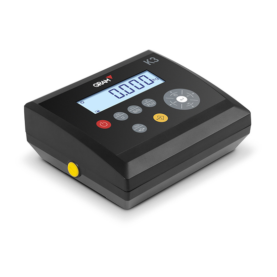
Page 8: Touch Pad Description
TOUCh PAD DESCRIPTION Power on/Power off. Press this button to turn on the scale. When the scale is on, pressing this button for approximately one second, will turn off the scale. Weight Unit change. Press this button to change the weight unit. In menu mode, it will work as an escape (return to normal mode) function. -
Page 9: Connections
MR and left arrow. Press this arrow to show the total accumulated weight. In menu mode, it verifies the selected adjustment value, and returns to the previous menu. M+ and right arrow. Press this arrow to have the device memorise the value shown on the display. -
Page 10: Platform 1 Connection
Platform 1 connection Multipin mobile connector. Male chassis socket P700 (7-pin). Load Cell A Load Cell b PIN 1 SIG - Blue White PIN 2 SIG + Brown Green PIN 3 SHIELD Shield Shield PIN 4 EXC - Black Black PIN 5 SENSE - Blue... -
Page 11: Unit Reset
UNIT RESET If the platform is empty and the display is not showing a value of zero, press to reset it. USINg ThE TARE Normal Tare Place a container over the platform. The scale will show its weight. When pressing the scale will show the “0”... -
Page 12: Fixed Tare
Fixed tare Place a container on the platform. The scale will show its weight. Press two times. The scale will now show the “0” value, subtracting the container’s weight. Now you can place other objects in the container and the display will show its net weight. -
Page 13: Using The Tare Memory
example “ILU 01”). The last two digits indicate the memory slot number. 3. Once the position of the memory slot you wish to use is selected. 4. Press the button, it will appear as a number on the display. 5. -
Page 14: Auto-Tare Function
To confirm press the button. The display will show the value of the memorised tare with a negative sign. Now you can place the product in the platform and the tare will be subtracted from the weight value showing the net weight. -
Page 15: Using The Function
3. Press the button to confirm. Press the button to return to weighing mode. Using the function 1. Place the container or box on the platform. The scale will perform the function. The display will show 0 and the tare symbol will be activated. 2. -
Page 16: Weight Sum Total
zero value. Press the button to select the weighing unit you want to use. Kg or g are shown by default, depending on the unit’s configuration. Place the object on the platform. The display will show the object’s weight. This value must be read when the “stability”... -
Page 17: Individual Counter Function
Remove the object from the platform. To weigh another object, make sure the display has returned to zero and the stability symbol is on. Press the button again and the second weighing value will also be added (it will be printed on a different ticket if the printer is plugged in and set up) ... -
Page 18: Counting
must be empty. Press and hold the button until the screen shows “10” or another flashing value. This is the number of pieces you can place on the platform to do the sampling. If the pieces are small, it’s recommended you put more than 10 pieces in order to increase the unit’s precision. -
Page 19: Individual Weight Counter
If you want to return to the individual counter function, and count pieces of the same weight used earlier, press the button several times until the display shows the “PCS” symbol. Individual weight counter Set the display to individual counter mode (“PCS” symbol and stability indicator should be on) and press the button. -
Page 20: Weight Test (Control +/-)
Keep the button pressed to access the memory database and retrieve a positon. The display will show “CLU XX”. XX is the memory slot. Use the buttons to increase or decrease the flashing digits value. Use the buttons to select the right or left digit. Once the required memory slot is selected, press the button to confirm. -
Page 21: Memorising Weight Limits And Response Mode
option of a relay card is available. It enables the connection of external warning or control devices. The scale has 20 memory slots assigned to this function. Memorising weight limits and response mode 1. Press the button and the scale will display the message “PLUPro”. Press the button to proceed. -
Page 22: Selecting Warning Mode
arrow buttons. 6. Press the button to proceed when ready. 7. Perform the same operation with the bottom increment. This value is usually the same as the top increment. In some cases it can be different and it must be specified. Warning Mode selection Warning mode must be set up for the limit function. -
Page 23: Activating The Limit (+/-) Function
1. No sound. 2. A single “BEEP”. 3. A continuous “BEEEEEEP”. Press the button to confirm the settings and exit with the button. The scale returns to regular weighing mode. Activating the Limit (+/-) function 1. Keep the pressed until seeing the “hi-Lo X”. “X” indicates if the ... -
Page 24: Product Code (Item)
5. Confirm the selection pressing the button. Press the button to exit. 6. Place the object on the platform. The scale will illuminate a part of the bottom bar (and the display colour will be green, yellow or red), depending on the weight value and the memorised limits. -
Page 25: Abcdefghijklmnopqrstuvwxyz Abcdefghijklmnopqrstuvwxyz
Press the button. You will see a flashing arrow to the left. The first character is highlighted by a flashing underscore. You can modify it with the buttons to select the one required. The values are shown according to the following order: ABCDEFGHIJKLMNOPQRSTUVWXYZ abcdefghijklmnopqrstuvwxyz 1234567890,’.:-_@... -
Page 26: Scanner Function
Scanner function This device allows uploading an item code through a scanner with a RS232C output, connected to the optional COM2 data input/output. This is a simple function. Once the scanner is connected to the COM2 port proceed to scan the bar code of the product. The scale will now memorise the last 6 digits of the code. -
Page 27: Hold Last Weight Value (Auto Hold)
Press to confirm the selected function. To exit press the button. hold Last Weight Value (Auto hold) Press the button to access the function menu. The display will show the “PLU XX” message. button, until the display shows “hold X”. The “X” digit Press the corresponds to the memorised option. -
Page 28: Auto-Off Function
Auto-Off function To access the function menu, press the button and the display will show “PLU XX”. Press the button until the display shows “AUt-0”. Press the button to proceed. The display will show a digit to the right, according to the following values: 1. -
Page 29: Using The Auto Tare
To activate the function, press the button, then press repeatedly the button until the display shows Aut-t 0. Set the right digit to “1” to activate the function. Use the arrow to set value. Confirm with and exit with Using the Auto Tare Make sure the display is showing “0”... -
Page 30: Stability Filter
Now “MEM 1” is going to appear. Press and then to exit the menu. Now you can set the empty memory slot to zero. Press the button for 4 seconds, and the display will show zero. To avoid incorrect zero settings, it’s recommended to go back to the previous menu. -
Page 31: Sound Activation
To change, press the buttons. Proceed with the button. To exit, press the button. Sound activation The touchpad has an option to enable sound when pressing the buttons. This sound can be disabled if not required. To enable the option, press the button, and then press until you see the “bEEP”... -
Page 32: Blocking The Touchpad
button to get to the “PCS” unit which corresponds to the individual part counter function. Perform the same procedure. When the task is complete confirm the changes with the button. To exit the menu, and return to the regular mode, press the button. -
Page 33: Internal Test
button, until you see the “ICouNT” message displayed. Press the button to proceed. The screen will show a 6 digit number that will usually be moving up or down. To exit this function, press the button and then press Internal test This function turns on the full display. - Page 34 Choose the required option with the buttons, confirm your selection with The message “Lr-P 0..2” will appear (Port redirection to simple ticket; 0 = deactivated, 1 = send by standard port, 2 = send by port 2, internal use). Select the desired option with the buttons, proceed with The message “ItMP 0..2”...
-
Page 35: Printing Format
PRINTINg FORMAT The printer data output can be set up with 5 different printing formats, according to the following versions: -‐ -‐ -‐ -‐ -‐ -‐ -‐ -‐ -‐ -‐ -‐ -‐ -‐ -‐ -‐ -‐ -‐ -‐ -‐ -‐ -‐ -‐ -‐ -‐ -‐ -‐ Format 1 ... - Page 36 -‐ -‐ -‐ -‐ -‐ -‐ -‐ -‐ -‐ -‐ -‐ -‐ -‐ -‐ -‐ -‐ -‐ -‐ -‐ -‐ -‐ -‐ -‐ -‐ -‐ -‐ Format 4 ...
- Page 37 buttons to modify the adjacent digit. Confirm the final value with the button. The message “Lan” will appear, followed by a number indicating the printing language. Select one of the following numbers for: 0. English 1. Spanish 2. French 3. German Press the buttons to choose the desired language.
- Page 38 show, 1 = show). Select the desired option with the buttons, proceed with The message “n tqt 0..1” will appear (Impression of ticket number; 0= Not show, 1 = show). Select the desired option with the buttons, proceed with A ticket number for the first ticket will appear. From there on the ticket numbers will start increasing.
- Page 39 The line will appear with the default characters (the factory’s name is printed by default). You can modify these characters. The first character is shown with a flashing underscore. With the button you can modify it according to the next table and in that same order: ABCDEFGHIJKLMNOPQRSTUVWXYZ abcdefghijklmnopqrstuvwxyz...
-
Page 40: Double Height Letter Size)
The message “Lin 3..1” will appear (line 1 impression; 0= print, 1 = small letter size, 2 = double height letter size, 3 = Double width letter size, 4 = Double width and double height letter size). Edit the third ticket line as described above. Once the editing is finished pro- ceed with the button. - Page 41 a “zero” between measurements. If this does not happen, the weight’s value will not be printed. To finish the ticket, press the button, then the footer and the subtotal (if it is enabled) will be printed.
-
Page 42: Guarantee
This unit’s warranty covers any factory and hardware defects. The warranty is valid for a period of 1 year from the date of delivery. Within the warranty period gRAM PRECISION, SL, will be responsible for the cost of any repairs. - Page 43 NOTIZEN...
- Page 44 001/08072016 Gram Precision S.L. Travesía Industrial, 11 · 08907 Hospitalet de Llobregat · Barcelona (Spain) Tel. +34 902 206 000 · +34 93 300 33 32 Fax +34 93 300 66 98 gram.es comercial www.gram.es...
Need help?
Do you have a question about the K3 SERIES and is the answer not in the manual?
Questions and answers